| John Broskie's Guide to Tube Circuit Analysis & Design |
16 December 2010
OTL for 50-Ohm Loads First of all, 72-ohm loudspeakers cannot be bought at your local hi-fi store (or anywhere else as far as I know). Sixteen-ohm loudspeakers, yes; 72-ohm loudspeakers, no. There are many reasons for this, some historical, some practical. In short, the 8-ohm standard has proved a good compromise and it is one of the few near universal standards we have in the audio world. Unfortunately, the 8-ohm load makes designing and building—and paying for—an OTL power amplifier a pain. If loudspeakers came in 300-ohm to 5kohm impedances, life would be much easier for the OTL fancier. Imagine being able to buy a 300B-based OTL power amplifier that used just two output tubes per channel and put out 40W into a 2500-ohm loudspeaker. Instead we are limited to OTL amplifiers that sport many high-current, but not-so-linear tubes such as the 6AS7 that are designed to drive 8-ohm loudspeakers. (By the way, when Julius Futterman designed and sold his famous OTL amplifiers, 16-ohm loudspeaker were easily purchased; had the array of available loudspeaker impedance been exclusively limited to 4 and 8 ohms, I am sure he would never had bothered to create his OTLs.) All of which brings us back to 72-ohm loudspeakers. Why 72 ohms?
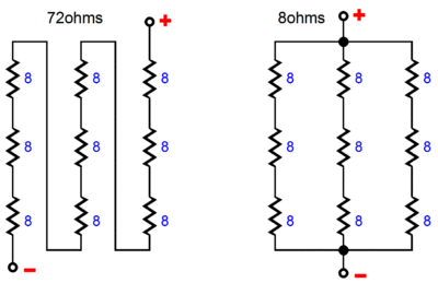
If nothing else, 72 is a cool number. It is, after all, "room temperature"; the exterior angle of a regular pentagram; the sum of four consecutive primes (13 + 17 + 19 + 23), as well as the sum of six consecutive primes (5 + 7 + 11 + 13 + 17 + 19); the number of conspirators who plotted against Osiris (the Sun God); the number of malevolent stars in Chinese astrology; the number of disciples sent forth by both Confucius and Christ (in Luke 10); the number of names of God in the Kabbalah, as well as the number of devils in the Lemegeton; the number of virgins a Muslim might get as a reward in Heaven; and the number hiden in Mona Lisa's left eye. It is also the resulting impedance from placing nine 8-ohm loudspeaker drivers in series.
72-Ohm Loudspeaker
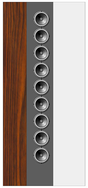
Imagine nine 8-ohm, full-range, 5-inch loudspeakers in a 45-inch long linear array. Such a loudspeaker would come close to approximating a true acoustic line source and would prove visually arresting. I can see building a simple dipole enclosure that didn't enclose, but only separated the back wave from the front, preventing too much bass cancellation.
Hardwood veneer, furniture grade plywood, sheet glass, and a long strip of grill cloth or wire mesh; say about 24 inches wide and 5.5 feet tall. No doubt such a loudspeaker would demand a subwoofer, possibly a super-tweeter. Interestingly enough, the 72-ohm loudspeaker's efficiency remains constant; although the sound-emitting surface has gone up by ninefold, the signal voltage each driver sees has gone down by ninefold—a wash, in other words. Thus, 87dB drivers would make an 87dB 72-ohm loudspeaker. The 72-ohm loudspeaker power handling would be nine times greater than a single driver, so a 30W driver would make a 270W loudspeaker. Not that we are likely to ever approach that many watts with a conventional solid-state power amplifier. Why not? The solid-state power amplifier that delivered 100W into an 8-ohm load can only deliver 11W into a 72-ohm load. In contrast, the OTL amplifier that could only deliver 16W into an 8-ohm load, can deliver 144W into a 72-ohm load. I wonder how many readers just said, "Ah, I get it!" The math behind such reasoning is simple. The 100W solid-state amplifier put out 40Vpk into 8-ohm load, which developed across a 72-ohm load, results in only 11.1W, as AC wattage equals Vpk²/2R. The tube-based OTL amplifier poured 2A (peak) into the 8-ohm load, which into a 72-ohm load, results in voltage drop of 144Vpk, which in turn equals 144²/(2 x 72) = 144W. Given the 72-ohm load, the solid-state power amplifier was voltage limited; given the 8-ohm load, the OTL amplifier, current limited. Because we choose to use nine 8-ohm drivers, we can easily rewire the drivers into an 8-ohm load, making our loudspeaker conventional amplifier friendly. I can imagine using a two-position, six-pole rotary switch to make the wiring alteration, which would yield several doubled-up contacts. What if we want to build a 72-ohm, two-way speaker? What I would do is to cluster six drivers, three tweeters and three woofers, into a single 24-ohm assembly. The three 24-ohm assemblies, then, could be configured in series for 72 ohms or in parallel for 8 ohms.
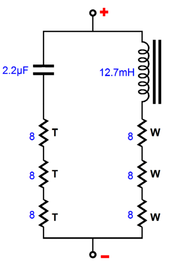
Note how in this simple, single-order 3kHz crossover, the inductor's value is three times greater than usual and the capacitor's value is three times smaller than usual; the math giveth and the math taketh away. There is no reason that a 27-driver, two-way or three-way, 72-ohm speaker could not be built in the same fashion; or that more complex crossovers could not be used. Think outside the 8-ohm box. By the way, when configured as an 8-ohm load, our nine-driver (or eighteen-driver two-way) loudspeaker would prove more efficient than you might expect, having not gained an efficiency boost from placing all nine drivers in series. Once again, the emitting surface has gone up ninefold, so we receive 20 x log(9) dB boost in efficiency; and since each driver sees 1/3 of the amplifier's output voltage, we lose 20 x log(0.33) dB in efficiency, not the 20 x log(0.11) dB loss that all the drivers i series incurs. The result is a 9.5dB boost in efficiency, making the 87dB driver yield 96.5dB of efficiency in our loudspeaker array.
One danger, I have to point out, with a 144W OTL designed to drive 72-ohm loads is that the loudspeaker will see 144Vpk across its terminals. In other words, the Underwriters Laboratories Inc. and your nanny would not approve, although trial layers in America would go shopping for a new Mercedes. A 144V is a lot of voltage; it is what the Japanese run their wall voltage. By the way, if a solid-state power amplifier could deliver 144Vpk into an 8-ohm loudspeaker, the wattage would equal 1296W. One easy workaround would be to use high voltage termination, both leaving the OTL amplifier and entering the loudspeaker, which would shield high-voltage wires from touch. Or, another possibility would be to build the OTL amplifier into the 72-ohm loudspeaker.
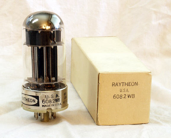
Unfortunately, a peak current swing of 320mA precludes using audio tubes like the 2A3, 6DJ8, 6SN7, 12B4, 300B, EL34, and, even, KT88—unless, of course, we don't mind using a bunch of them. The two obvious choices are the 6AS7 and the 6C33. Actually, we can add to this list the 6080 and 6082, which are industrial versions of the 6AS7, with the 6082 holding a 26.5V @ 600mA heater. Its 26.5V heater is a blessing, if a regulated heater power supply is used, as the 6AS7's 6.3V @ 2.5A heater would overburden most low-voltage regulators. The 6082 is getting expensive, as it used in a collectable Collins radio; the 6080, on the other hand, is dirt cheap and readily available and shares the 6082's cool bullet-like shape, but shares the 6AS7's 2.5A heater draw, alas.
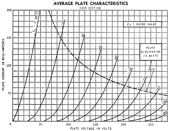
Inspecting the 6AS7/6080/6080 plate curves proves a bit exasperating, as the graph stops at 200mA. Of course, we can extrapolate out to 320mA, but I know from much firsthand experience that a single 6AS7 triode will draw over 500mA with a 0V grid voltage and cathode-to-plate voltage of 100V, which would work well with our required 320mA peak current swing. Before going further, note that 6AS7's plate current limit is only 150mA and that its plate dissipation limit is only 13W. In other words, can we get away with just one 6AS7 per channel? The answer depends on the signal source and your willingness to damage your hearing. If steady sine waves at full power are expected, the answer is no. If wide dynamic-range music and moderate average listening levels the norm, then the answer is yes.
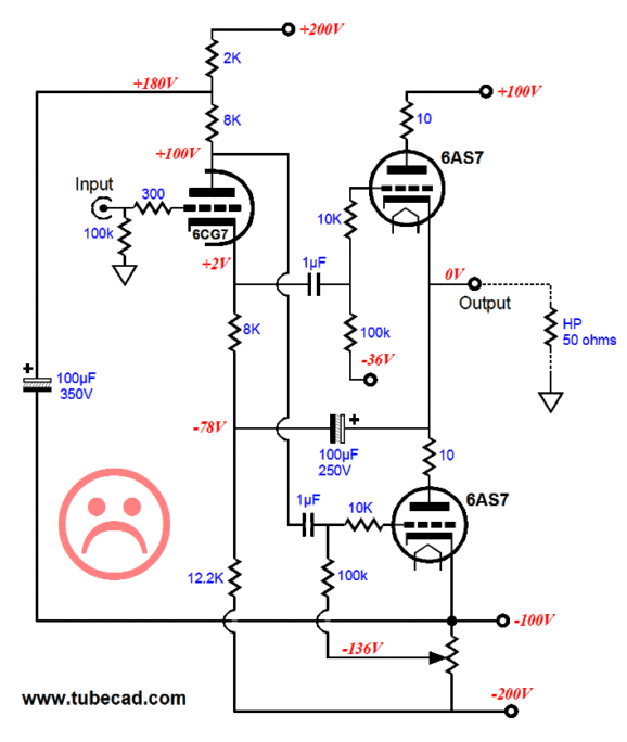
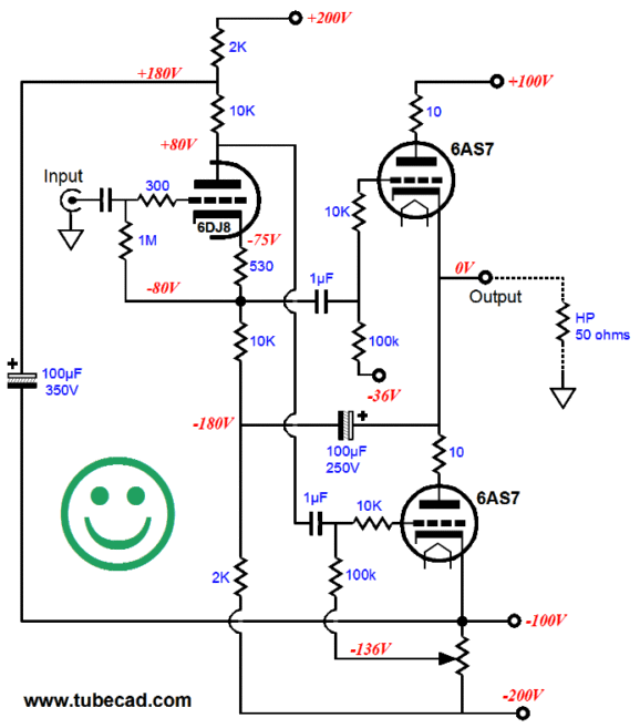
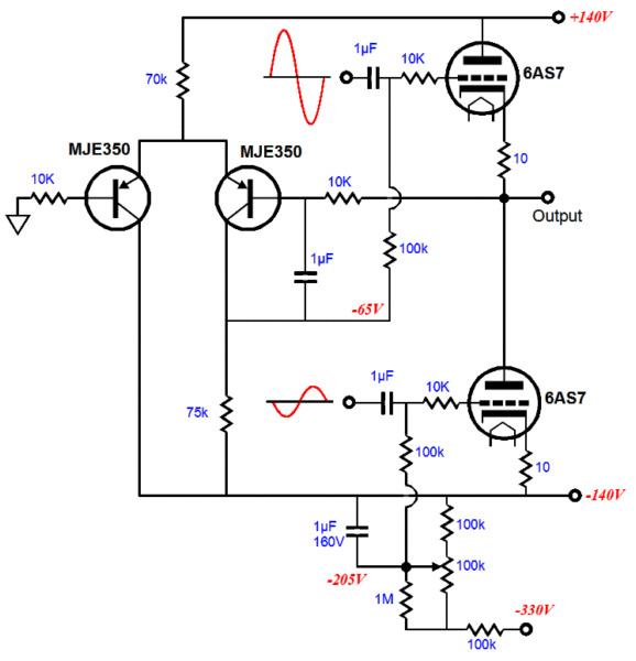
Even without the plate curve, we could quickly test a single 6AS7's suitability. At plate currents in excess of 250mA, the 6AS7's plate resistance falls to about 150 ohms. Now, 150 ohms in series with 50 ohms equals 200 ohms, which divided into 100V equals 500mA, with 25V imposed across the 50-ohm load and 75V spanning the 6AS7's cathode to plate. (Even with the tube manual's stated rp of 280 ohms, the math reveals that over 300mA of swing would be obtainable.) The next design choice is to decide whether we should give the 6AS7 more than 100V of cathode-to-plate voltage, the greater plate voltage allowing it to deliver more peak current; or should we retain the 100V cathode-to-plate voltage (or even less voltage), but greatly increase the idle current. We cannot do both high plate voltage and high plate current, as we will exceed the tube's maximum plate dissipation limit. My choice would be to go for a high idle current, at the expensive of a curtailed peak current swing, as the 6AS7 triode is not very linear at low currents. For example, with a 20mA current draw with a cathode-to-plate voltage of 100V, the 6AS7's rp climbs to 770 ohms. With a cathode-to-plate voltage of 100V, I would run an idle current of at least 70mA through the 6AS7. Very spongy indeed. Working backwards, we have to decide on the power supply configuration and the phase splitter topology. (I assume a class-AB, push-pull headphone amplifier, as 320mA current swing from an single-ended amplifier or class-A push-pull would demand more output tubes in parallel.) The chief advantage of a bipolar power supply allows direct coupling to the headphones. On the other hand, a coupling capacitor, albeit a large-valued capacitor (at least 160µF with a 50-ohm load), would certainly prove safer. The split-load phase splitter is both simple and amazingly effective. Moreover, this phase splitter allows us to easily setup the correct drive signal balance for both 6AS7 triodes. The following schematic shows such a setup, but it holds a flaw.
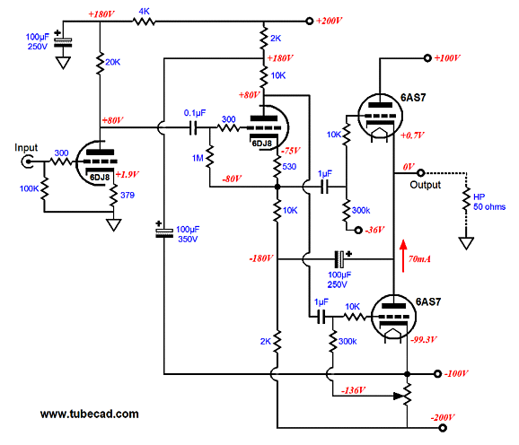
There is much to like here. The 100µF capacitor that bridges the output to the phase splitter ensures that the top triode gets a bigger input signal than the bottom triode and it delivers an equal output impedance from both triodes. The 10-ohm plate resistors prevent oscillations. The 100µF capacitor that connects the phase splitter to the negative power supply rail prevents noise from the negative power supply rail from getting into the output. In fact, this topology is far more coherent and subtle than most Stereophile Class A OTL power amplifiers. Nonetheless, it holds a flaw—namely, the split-load phase splitter cannot swing a big enough output signal to drive the output stage to full output. Why not? The 6CG7's rp is too high; or the +/-200V power supply rails are too small, which would prove a truly amazing situation wherein 400V of operating voltage is inadequate. Thus, the more likely culprit is the phase splitter's triode. Notice how the 6CG7's 8k plate resistance equals the anode and cathode resistor values, which means that when the 6CG7's grid is at the same potential as its cathode (0V grid voltage), the top 6AS7 triode will see its peak positive grid voltage swing. Given the 280V of voltage, after the voltage drops across the 2k and 12.2k resistors are subtracted from the 400V, that the split-load phase splitter works within, the peak cathode swing is only about 15V. A lower rp triode, such as the 6DJ8 or 5687, would allow much bigger phase splitter voltage swings. Remember that as the output stage swings positively, the 100µF capacitor that connects to the output and the phase splitter's 12.k resistor will pull up on the phase splitter's bottom 8k resistor, reducing the available working voltage for the phase splitter. The best workaround is to more effectively use the 400V, as shown in the following schematic.
In this design example, only 40V of the potential 400V is withheld from the phase splitter, leaving a 360V window for to operate within. Furthermore, the low-rp triode (6DJ8/6922/7308/ECC88) makes for a smaller voltage drop at maximum current draw (Vg = 0V). As it stands, this is a fully functional tube buffer stage. Making a complete tube-based OTL headphone amplifier requires an input gain stage. This OTL headphone amplifier seems straightforward enough, with just two tubes per channel; no negative feedback loop spans from output to input; and the input tube develops a gain of about 18 (+25dB). This amount of gain, however, would probably prove insufficient, as the output stage will require huge input voltage swings to make the 16Vpk output requirement. A better choice might be a 12AT7 or 6072. In fact, a more complex input stage could certainly be used.
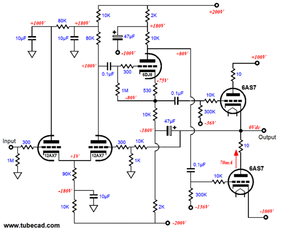
The cathode-coupled amplifier input stage yields enough gain to power a negative feedback loop. In addition, it offers low input capacitance and no phase inversion. Notice how if I had started with this schematic, it would most likely seem far too complex to understand. But now, after having taken several baby steps, it does not seem that complicated. (I remember reading that an editor of a high-brow magazine had received a letter from a reader who loved the magazine, but took exception to all the big words that filled its pages, so he requested that the editor prohibit their inclusion. A year later, the same reader wrote back thanking the editor for his purging of the offending big words; of course, the editor hadn't.)
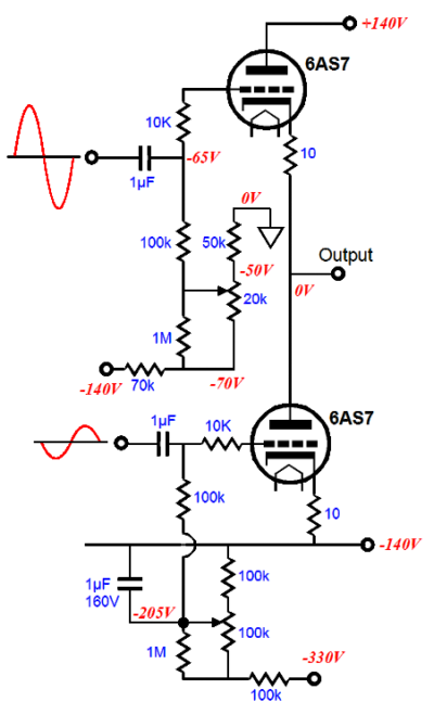
Biasing OTL Output Stages
The bottom potentiometer adjusts the idle current through the output stage and must be adjusted first. The top potentiometer adjusts the DC offset and must be adjusted last. Of course, the headphones must not be attached while these adjustments are made. The following circuit automatically adjusts the DC offset, while the idle current must still be manually adjusted. The two PNP transistors define a differential amplifier that compares the DC output voltage to the ground voltage, slowly auto adjusting the bias voltage for the top 6AS7 triode to reduce the DC offset.
OTL Power Supply
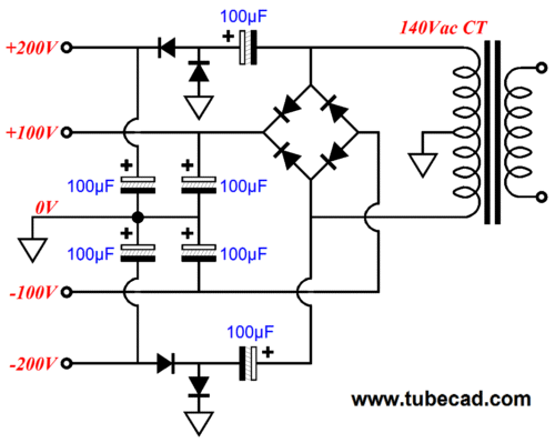
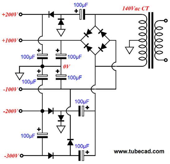
The two 100V rails get a full-wave bridge rectification, while the two 200V rails make do with half-wave voltage doublers. The assumption here is that input and driver stages will draw so much less current than the output stage that the greater half-wave rectification noise can be filtered away with simple RC filters. (I have used this power supply topology many times before; I found that it was a godsend when designing solid-state power amplifier with MOSFET output devices, as the voltage-doubled power supply rails allowed the VAS driver stage to swing beyond the MOSFET's drain voltages, making full power output possible.) Of course, we could implement full-wave voltage doublers at the expense of two more 100µF capacitors and four more rectifiers. We are not done, as we need an even more negative rail to bias the output stage's bottom 6AS7 grid.
Next Time
//JRB |
|
Kit User Guide PDFs
E-mail from GlassWare customers:
And
High-quality, double-sided, extra thick, 2-oz traces, plated-through holes, dual sets of resistor pads and pads for two coupling capacitors. Stereo and mono, octal and 9-pin printed circuit boards available.  Aikido PCBs for as little as $24 http://glass-ware.stores.yahoo.net/ Only $12.95
Version 2 Improvements Download or CD ROM www.glass-ware.com To purchase , please visit our Yahoo Store:
|
||


| www.tubecad.com Copyright © 1999-2010 GlassWare All Rights Reserved |