| John Broskie's Guide to Tube Circuit Analysis & Design |
01 April 2006
Gentlemen, start your irons!
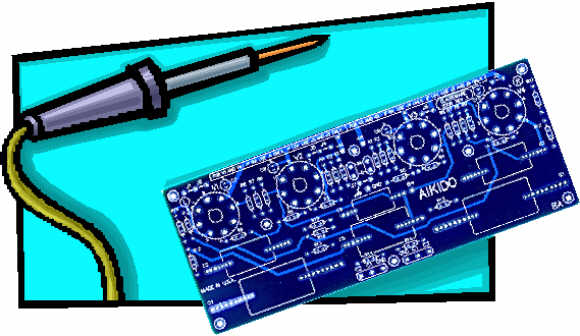
More Aikido PCBs (no joking) 
But instead of a joke, I have good news. The new batch of Aikido and stepped attenuator printed circuit boards are here. I picked them up in person at Bay Area Circuits yesterday in Redwood City, California. I got a 45-minute tour of the production floor and I was impressed with everything I saw and everyone I met. I was tickled to read the names of many of Silicon Valley’s biggest players on the boxes of PCBs sitting on the same same shelf as GlassWare Audio Design PCBs. Without a doubt, this is the PCB house I plan to use from now on. The fellow I worked with was Ron Charfauros, a many-decade veteran of PCB creation. So, how do the new boards look? Excellent; better than the previous run, in fact. First of all, I must explain that I am exceedingly picky when it comes PCBs, as most would not spot any difference from the last run. So what do I spot? The silk-screened part placement guides are much finer and more cleanly printed. The color is closer to the blue-blue-green I was eager for (unfortunately, all PCB board is now UV blocking, which means that it is a light yellowish color that makes any pure color other than yellow impossible to realize). And the board’s edges are smoother. Changes to the boards that do not require a hyper-pickiness to spot are found in the board’s layout. Both Aikido PCBs are now in revision A. (The grid-stopping resistors have been rearranged to bring them closer to the grids and the heater pads are a tad fatter.) These changes have altered the resistor numbers a tad, so be sure to follow the schematic that reads “REV A.” So should you worry if you have the old-style boards? No. The changes are too minor to cause any concern.
Hybrid Aikido Amplifiers 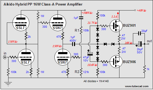
Why only 16 watts, when the power MOSFETs could deliver an easy 100 watts or more in another amplifier? Class-A is better. It offers the lowest distortion and the flattest output impedance. However, like most things worth having, it isn’t cheap. This 16-watt amplifier runs a high 1.1A idle current, which results in each output device dissipating 22 watts at idle (well within the DC safe operating limits). If 16 watts seems ridiculously low to you, then you could convert the amplifier to class-AB and double the power supply voltage to +80 volts, which would yield an easy 60 watts of output. Such a change would require changing the output stage’s voltage reference, as careful adjusting would be essential. 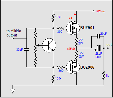
But once again, which would you prefer to have: a bar of absolutely delicious chocolate or a bucket of Hershey’s chocolate? (And, once again, if you choose the latter, why are you reading this journal?) A single-ended hybrid amplifier is just as simple to realize, although at the cost of only half the efficiency of the push-pull version. (Inductively-loaded single-ended amplifiers share the same 50% theoretical maximum efficiency as do push-pull class-A amplifiers.) In other words, in order to get the same 16-watt output, the single-ended version will require twice the idle current that the push-pull version needs. This means that at idle, each power MOSFET will dissipate at least 40 watts. 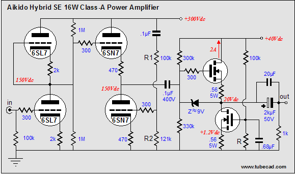
The output devices do not have to be BUZ901s, although I do like them best. But I can see where their high cost and limited availability might tilt the table in favor of the International Rectifier HEXFETs.
A Zen-like variation would be to use a grounded-source amplifier in the output stage, instead of the source-follower. Why? Such an arrangement would invert the phase, which would effectively restore the phase, as the Aikido amplifier inverts as well. With the output signal in phase with the input, a feedback loop can be brought back to the input tube’s cathode. The feedback loop would encompass both the tubes and the MOSFETs and yield the lowest possible THD, but at the cost of higher harmonics being added to the output. Is this desirable? I don’t know, as I haven’t built such an amplifier, but my guess is that the feedback-free version would win in listening contest. (Actually, the source follower contains its own feedback mechanism and the two THD figures would not differ to substantially, as in both amplifiers there isn’t that much transconductance to work with.) The constant-current source that loads the bottom output MOSFET is not a true constant-current source, but rather a compliant-current source. It strives to maintain the same DC output voltage, regardless of the current flowing through the output stage. Yes, it does require an internal coupling capacitor, but it also self-centers without a goosey feedback loop. Of course, transistor output stages could be used with the Aikido amplifier. Why? Well, they are cheap. A good transistor cost only one dollar, whereas a good MOSFET goes for seven dollars. (By the way, be aware of the growing problem of counterfeit electronic parts: cheap parts relabeled as the expensive version. Flea market and eBay buyers watch out. Just because a part is labeled an OPA627 or MJ1501 does not mean that that is what the part is on the inside.) The idea below is to use a very simple unity-gain transistor buffer circuit as the output stage of a hybrid amplifier. This the idealized schematic. The real schematic looks more like this: The DC offset is set with the aid of the potentiometer. The biasing is separate from the fuses, so that the output does not slam to one rail, should one fuse blow. The electrolytic capacitor greatly reduces the distortion. The two diodes protect the buffer from inductive kickbacks. Why build this circuit? It would be dirt cheap is the answer (most of us have all the parts we need in our part pins already). For more power buffer ideas see the article on power buffers. Next time //JRB
|
Help keep the
The Tube CAD Journal's first companion program, TCJ Filter Design lets you design a filter or crossover (passive, solid-state or tube) without having to check out thick textbooks from the library and without having to breakout the scientific calculator. This program's goal is to provide a quick and easy display not only of the frequency response, but also of the resistor and capacitor values for a passive and active filters and crossovers. TCJ Filter Design is easy to use, but not lightweight, holding over 60 different filter topologies and up to four filter alignments: While the program’s main concern is active filters, solid-state and tube, it also does passive filters. In fact, it can be used to calculate passive crossovers for use with speakers by entering 8 ohms as the terminating resistance. Click on the image below to see the full screen capture.
Tube crossovers are a major part of this program; both buffered and un-buffered tube based filters along with mono-polar and bipolar power supply topologies are covered. Available on a CD-ROM and a downloadable version (4 Megabytes). Download or CD ROM
|
|||


| www.tubecad.com Copyright © 1999-2005 GlassWare All Rights Reserved |