| John Broskie's Guide to Tube Circuit Analysis & Design |
25 December 2015 (Post updated on May 27 2018)
Gratuitous Christmas Image
Interestingly enough, as a teenager she fell ill to facial palsy, paralyzing the left side of her face, but which she recovered from later. Well, many believe that she never fully recovered, which resulted in her famously calm expression. (I once had a lovely girlfriend whose two front teeth held a gap, much like the model and actress, Lauren Hutton, so my girlfriend seldom smiled a big Miss-America-toothy grin in public, preferring to to keep her lips constantly together even when smiling. The effect was to project, in complete opposition to her actual demeanor, a haughty reserved bemusement: altogether enchanting, although it also made her seem unapproachable.)
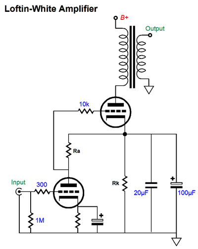
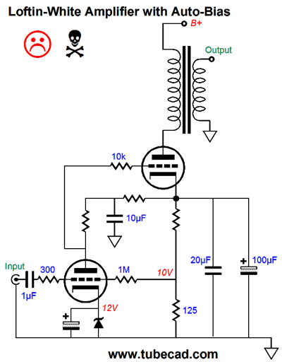
Loftin-White Amplifier Revisited
The advantages are that many fewer parts are needed, as no coupling capacitor is used and the output tube and output transformer primary's inductance shield the input tube from the power-supply noise. Okay, what is not to like here? The danger we face is that if the input tube is faulty or missing from its socket, the output tube becomes over biased.
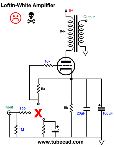
The output tube's grid and cathode see the same DC voltage and the tube conducts wildly. The formula is as follows: Iq = Vb / (rp + Rk + Rdc where Vb is the B+ voltage; rp, the output tube's plate resistance; Rk, the output tube's cathode resistor; and Rdc, the output transformer's primary DC resistance. Let us assume a B+ voltage of 560Vdc and an rp of 700 ohms and an Rdc of 100 ohms and an Rk of 2.5k ohms. These values would yield an Iq of 170mA. This much current through the cathode resistor would develop a voltage drop of 425V, which will result in 72W of heat dissipation from the resistor and a lot of smoke, as it bursts into flames. Even if a 100W cathode resistor were used, we face the problem of the bypass capacitor being exposed to excessive voltage. In short, DC coupling is a pain.
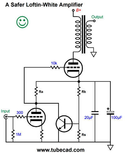
A Safe Loftin-White Amplifier Revisited
The added NPN transistor and current-sense resistor, Rs, impose a current limit. Once the idle current is sufficient to develop a large enough voltage drop across resistor Rs to turn on the NPN transistor, the transistor's collector will pull down the output tube's grid voltage. I would set the trip current to about 125% of the desired idle current. For example, if an idle current flow of 80mA is desired, then 100mA is the trip current. Under normal operation, the NPN transistor is turned off and effectively out of the circuit. This transistor would also save the day, should the output tube become gassy and conduct too much current. An LED could be placed in series wit the transistor's collector, as it would function as an error-condition indicator. Another thought is, Why not use a constant-current source in place of the cathode resistor?
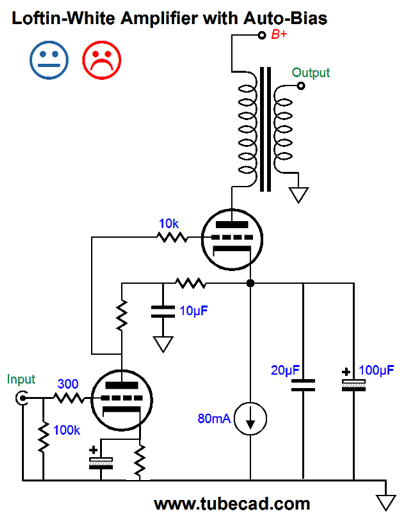
This looks good, but reality is sure to disappoint. How so? A 300B output tube only requires about 75V from cathode to plate to draw 80mA with 0V grid-to-cathode voltage, which means that the constant-current source and the bypass capacitors must see the rest of the B+ voltage. Here is another possible auto-bias version.
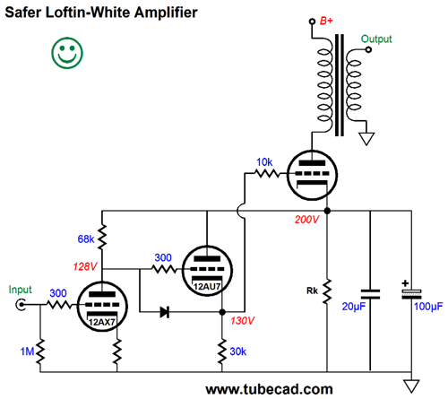
Although the auto-bias would work well with the input tube in place and functioning correctly, the design fails the no-tube test. One workaround is to add a cathode follower.
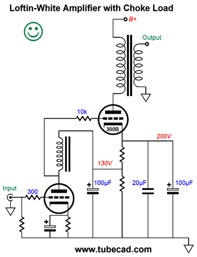
The 12DW7 holds two dissimilar triodes, one with 12AX7 characteristics and one with 12AU7 characteristics. Should the input tube be absent from its socket, the diode will become forward biased and conduct, placing the 68k and 30k resistors in series, so the output tube's grid can never be as positive as its cathode becomes without the input tube. This solution is not perfect, as the limited voltage available to the input triode and cathode follower limit the maximum positive voltage swing to the output tube's grid. Still, it is interesting. Perhaps, it would work even better without the diode. Another possibility is use an inductive load for the input tube and two cathode resistors in series.
The inductor/choke approximates a constant-current source, yet it does not displace any DC voltage (well, very little, as no inductor is perfect). The top cathode resistor limits the maximum DC grid voltage the output tube can see, which makes this a much safer design. We can even replace the top cathode resistor with a solid-state constant-current source.
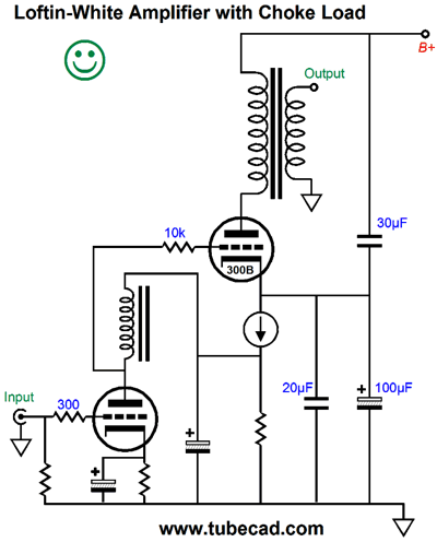
The remaining problem is finding a high-quality inductor, one with both high inductance and low DCR. Good luck. What if we replace the inductor with an active circuit?
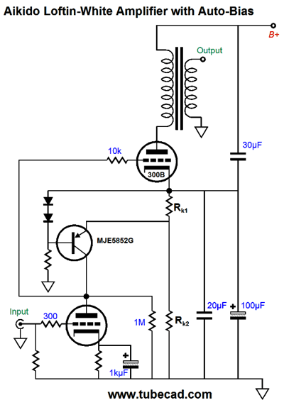
This variation uses a high-voltage PNP transistor and two diodes to establish a reference voltage to compare against the voltage drop across resistor Rk1. If the voltage drop across the resistor is too great, the transistor turns off and the output tube's grid voltage falls. Conversely, if the voltage drop across the resistor is too small, the transistor turns on and the output tube's grid voltage rises. Auto-bias in a nutshell. How did the word "Aikido" sneak into the title? The addition of the 30µF capacitor delivers a huge reduction in power-supply noise leaking into the loudspeaker.
See blog number 308 for more details. The key is that the top capacitor be smaller in value than the bottom capacitor. By how much? By 1/mu as much. Let's move on to a more fleshed-out design.
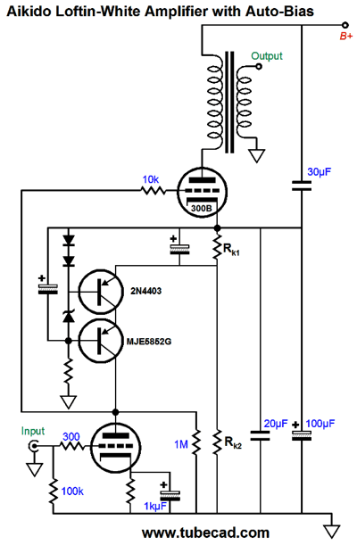
Most, if not all, of the bells and whistles are in place. The cascoded PNP transistors produce a higher output impedance (a closer approximation to constant-current sourcing) and lower noise. The added electrolytic capacitors also help shunt away noise. The 1M resistor provides a current path for the transistors should the input tube be missing in action. The zener can be a low-voltage type, say 3.3V, a 1N5913B for example. Bear in mind that the input triode's own current conduction will flow through the current-sense resistor, Rk1. Thus, this current must be factored in the equation. For example, if we desire an idle current flow of 80mA from the output tube and the input tube draws 10mA at idle, then we must expect that 70mA will flow through Rk2 and 80mA through Rk1.
A Safe and Quiet Loftin-White Amplifier
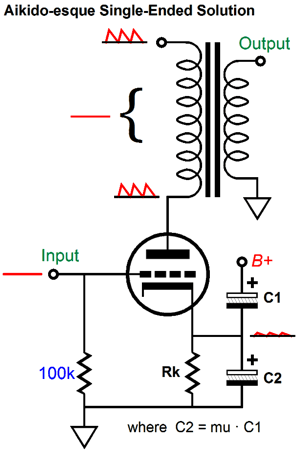
We keep the DC coupling between input tube and output tube from the original Loftin-White amplifier and we add safe auto-bias and Aikido-esque PSRR enhancement. What if you want to use only half of the Aikido-esque PSRR enhancement, go UltraPath, in other words?
I can see why many would be seduced by such a move, as it requires no math and many of your friends have told you that UltraPath is ultra cool, indeed, that it is the bomb. Math? Yes, I know that most would not find the formula C2 = mu x C1 overly complex, but most do not suffer from math anxiety; some however do. Others are seduced by the name, "UltraPath." In any case, first reread blog 147 (which is one of my best efforts). Then look over the following schematic.
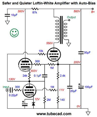
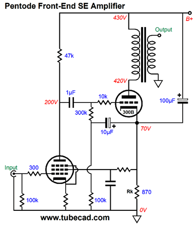
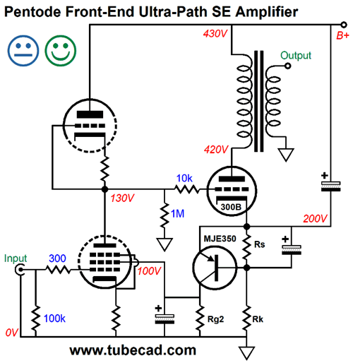
Note how the input pentode's plate resistor connects directly to the B+ connection with no intervening RC filter. Also note how the 10µF capacitor connects the 300k resistor to the 300B's cathode. Why?
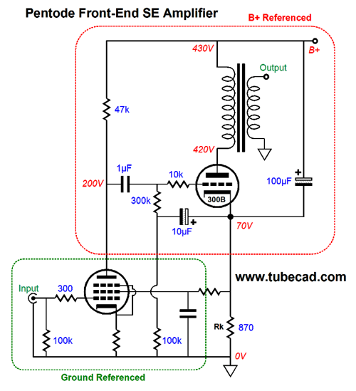
We want the 300B's grid and cathode to see 100% of the power-supply noise, as this will result in the 300B being immune to the noise. In the red band we see all the parts that are B+ referenced; in the green band, all the ground referenced parts. Note that this amplifier is not a Loftin-White design. The following design, however, moves back towards a Loftin-White design.
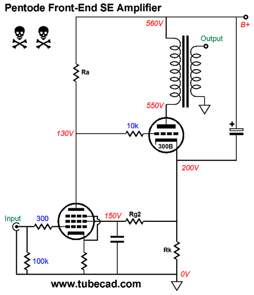
Danger, danger! This is the sort of circuit that works fantastically well in the virtual world of SPICE simulation, but farcically fails in the real world. Why? If the pentode is missing from its socket or slow to warm up, the 300B output tube sees the full B+ voltage on its grid. Not good. Here is a possible workaround.
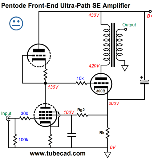
The idea behind this circuit is that a tube that holds a triode and pentode, such as the famous 6U8, could be safely used. Maybe. If the input tube were missing from its socket, the 300B's grid could not connect to the B+ voltage, as the triode above the pentode would also be missing. Resistor Rg2 is attached to the 300B's cathode, so that a mild form of auto-bias obtains. The indecisive face is there as I have doubts about how well such an auto-bias will work with an aging input tube. Here is a workaround that should prove much more reliable.
The pentode's grid-2 (screen) is still used to set its idle current, but the PNP transistor, say an MJE350, controls the grid-2 voltage, as this transistor monitors the voltage drop across resistor Rs and strives to maintain a fixed voltage drop equal to its base-to-emitter voltage. Imagine that the 300B is not conducting enough current to turn on the transistor, which would mean that input pentode's screen would see 0V, which in turn would reduce the pentode's idle current flow, thereby allowing the triode-based active load to pull up the pentode's plate voltage, making the 300B see a more positive grid voltage, causing the 300B's current conduction to increase. If the 300B over shoots the desired idle current, the PNP transistor will turn on and pull up the screen voltage just to the point where the 300B is sufficient to develop a voltage drop across resistor Rs equal to the MJE530's emitter-to-base voltage, about 0.6V to 0.7, depending on the transistor's temperature.
Next Time
User Guides for GlassWare Software
For those of you who still have old computers running Windows XP (32-bit) or any other Windows 32-bit OS, I have setup the download availability of my old old standards: Tube CAD, SE Amp CAD, and Audio Gadgets. The downloads are at the GlassWare-Yahoo store and the price is only $9.95 for each program. http://glass-ware.stores.yahoo.net/adsoffromgla.html So many have asked that I had to do it. WARNING: THESE THREE PROGRAMS WILL NOT RUN UNDER VISTA 64-Bit or WINDOWS 7 & 8 or any other 64-bit OS. I do plan on remaking all of these programs into 64-bit versions, but it will be a huge ordeal, as programming requires vast chunks of noise-free time, something very rare with children running about. Ideally, I would love to come out with versions that run on iPads and Android-OS tablets. //JRB |
Kit User Guide PDFs
E-mail from GlassWare Customers
High-quality, double-sided, extra thick, 2-oz traces, plated-through holes, dual sets of resistor pads and pads for two coupling capacitors. Stereo and mono, octal and 9-pin printed circuit boards available.  Aikido PCBs for as little as $24 http://glass-ware.stores.yahoo.net/ Support the Tube CAD Journal & get an extremely powerful push-pull tube-amplifier simulator for TCJ Push-Pull Calculator
TCJ PPC Version 2 Improvements Rebuilt simulation engine *User definable
Download or CD ROM For more information, please visit our Web site : To purchase, please visit our Yahoo Store: |
|||


| www.tubecad.com Copyright © 1999-2015 GlassWare All Rights Reserved |