27 July 2010

Yes, I know that it’s been a long time since my last post. I am still catching up and I am working on a new production run of PCBs. In addition, my kids are on summer vacation.
The Broskie cathode follower (BCF) is old news, having made its first appearance back in the June 1999 issue of the TCJ, and reappearing in October of 1999. (I actually came up with the circuit about a decade earlier, but it mostly languished in one of my notebooks.) After I published the circuit, I received laudatory e-mail mostly from electrical engineers who worked with balanced audio signals. (DIYers and audiophiles either didn't need the circuit or they didn't understand how it worked; probably, mostly the former, as I have met very few audiophiles who ran balanced systems.)
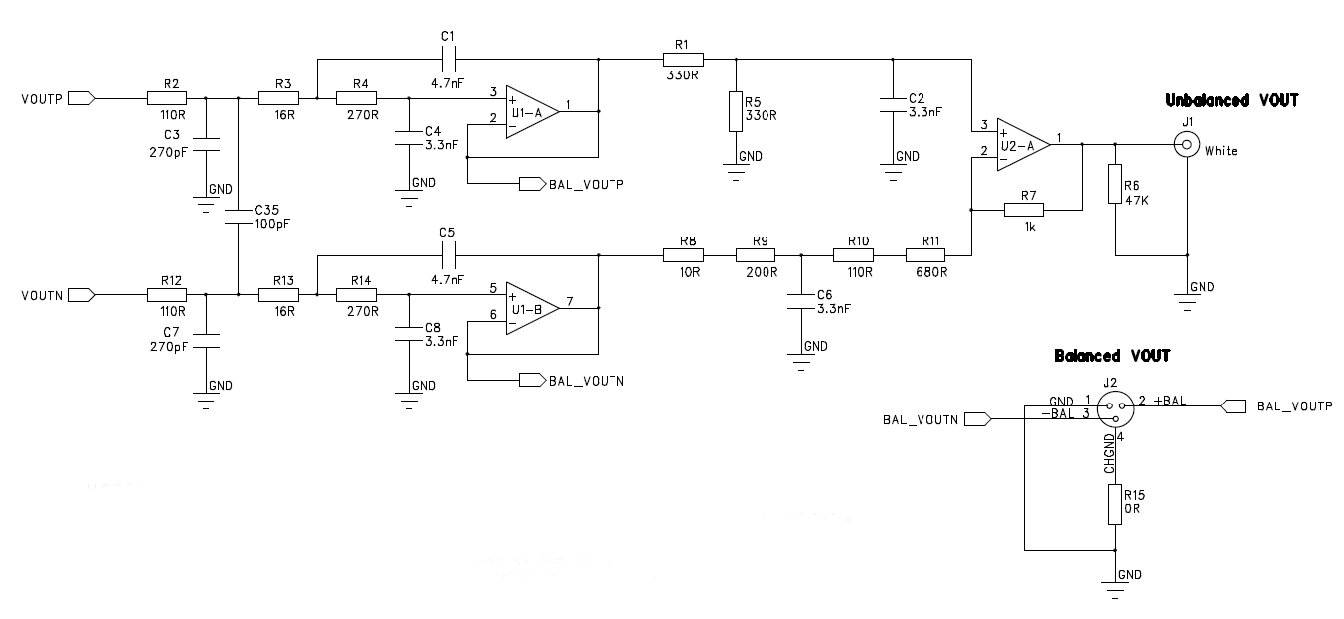
I remember getting e-mail from a recording engineer in Europe who just loved the circuit and replaced as many signal transformers as he could with a BCF. And one TCJer wrote me telling me that the BCF worked perfectly at driving his Sennheiser HD580s; I was sure he was wrong. But after I hooked up my own pair of HD580s, I realized that he was right. It sounded fabulous. Unfortunately, at the time, I didn't own any balanced gear, making me resort to using inter-stage transformers for testing the BCF, so I couldn't directly take advantage of the circuit's stellar performance. But once I got my Cambridge Audio DacMagic, I had a balanced output just waiting to be used. Below is a schematic from a DAC data sheet and it shows how many standalone DACs ad CD players implement both balanced and unbalanced outputs. Note how the balanced outputs bypass the extra OpAmp. Less is more.
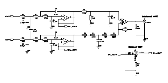
Click on image to see close up
In 2009, I laid out a PCB for the BCF and I had production run made. But I didn't want to release the boards until I had thoroughly tested them, both electrically and sonically. Well, the tests are finally over and the PCBs are up for sale at the GlassWare/Yahoo Store.
Speaking of testing, I had the oddest results. At first it hummed as if it was possessed by Satan. I discovered that I had broken the connection that grounded the chassis. After the repair, the hum was gone, entirely gone. The sound, however, was way off, sounding eerie, distant, and solid-state-like. I broke out a fav jaz album of mine: In love by The Jazz Passengers.

This was an odd choice, as the album never sounds good on solid-state equipment, which is just another reason why I like tube gear so much. In spite of a room filled with tubes, it sounded very solid-state. I let circuit burn in for an hour and gave it another listen. Now it was much much better, but not perfectly on the mark. I waited another four hours or so and then it sounded quite good. By the next day, it sounded great. I do not know which parts were to blame. The Jupiter caps, the tubes? I have seen graphs that show how it takes a new vacuum tube about 20 hours of operation to settle down. Or, maybe the beeswax needs to be formed; yet this didn't happen the last time I used them.
In general, I do not believe in audio gear needs breaking in, as I am convinced that is usually the listener who breaks in, not the the electronic components. We must learn to listen. Indeed, I would love to perform a test, wherein two identical pieces of gear were double-blind auditioned, except that one was fresh out of the box and the other had been in use for weeks. My guess is that both would seemingly undergo a similar break-in period, a learning period. Having said that, I must admit that I have encountered recalcitrant parts, usually capacitors. I remember one of my tube-based ES headphone amplifiers sounding dreadful for about an hour before the the sound improved. This drove me crazy, so I used a hair dryer to find the offending capacitor, a power supply capacitor.

When toasty warm, the capacitor did it job; but when cold, it added a harsh texture overlay to the sound. I then swapped in and out capacitors until I found a capacitor that only took five minutes to come up to speed (a photo-flash type). I am sure that the Stax ES headphones revealed this capacitor defect far more readily than any dynamic headphone could (and which no loudspeaker could do). Once again, a fun test would be to compare two identical pieces of gear, one that came out of the freezer and one that sat in the hot Colorado sun.
One manufacturer of high-end-audio gear told me that he believed that all solder joints must be reheated to melting a few days after their initial soldering. Why? His view was the first soldering left the joint in a stressed condition, but the second soldering allowed the stresses to be relieved. Thus, he had each solder joint remelted with a butane-powered flame before his gear was packaged up for shipping. He might be on to something, as resoldered joints look different from one-time solder joints.
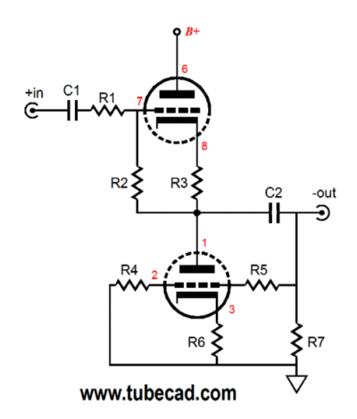
The BCF receives a balanced input signal and converts it to an unbalanced output. It is a unity-gain buffer (actually a gain of 0.5, so the two phases added together equal 1) that offers a high input impedance, low output impedance, low distortion, and great CMRR. In addition, because the BCF uses a push-pull topology, its use is not limited to line-stages, as the BCF can be used as a headphone buffer-amplifier if the headphone's impedance is high enough (say, 300-ohms). In addition, much like a signal transformer, the BCF offers common-mode signal rejection (CMRR); this means that BCF passes differential input signal, but largely ignores what is common to both input signals. Why is this a feature?
Common-mode signals are extraneous to the actual input signal and usually consist of hum, power-supply noise, and RFI. The key advantage that a balanced signal offers is the chance to apply a high-CMRR transformer or circuit, which will then scrub away the added electrical contamination. The problem with using a high-quality signal transformer is cost: good transformers are both rare and expensive.
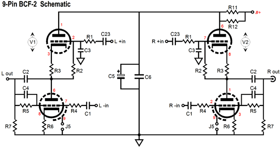
The BCF PCB, like the ACF board, is an amazingly simple affair, holding two tubes, one per channel (two triodes per per channel) and a handful of capacitors and resistors, only four by six inches. It requires an external power supply, which can hold a B+ voltage as low as 24V (6GM8/6N27P/ECC86) or as high as 300V (6CG7 or 6H30 or 12BH7 or ECC99). The PS-1, PS-3, PS-4 would work well.
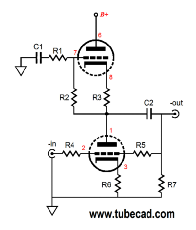
Interestingly enough, if the BCF receives only one input signal phase, presented to either the top or bottom input, with the other input grounded, it still works— extremely well—but incurs a -6dB insertion loss. Here is the non-inverting configuration:
And inverting:
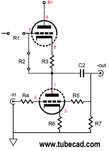
This variation can be further modified to:
The insertion loss can be a problem, of course; but if the extra gain is not needed, this arrangement offers some interesting possibilities. For example, we could use the BCF to invert the phase of an unbalanced input signal. Imagine a rotary switch with three positions: non-inverting, mute, inverting.
(The mute at the center is critical I have found, as the ear needs a second or two to reorient itself to the change in phase. Try it yourself with a toggle switch; you'll find that you cannot hear the phase reversal when the switch is quickly flipped back and forth, but you can readily hear the difference when you mute in between phase flipping.)
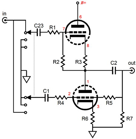
Now we finally arrive at what I plan on setting up. I will use my select-2 PCB and rotary switch to achieve the following setup.
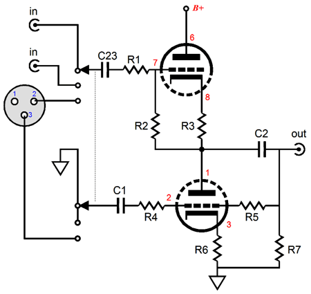
Two unbalanced inputs and one balanced input per channel. Note the lack of cathode resistor bypass capacitors. I do not need a super-low output impedance and I try to avoid electrolytic capacitors, even the best electrolytic capacitors, in the signal whenever possible.
To get the lowest output impedance, the BCF's cathode resistors must be bypassed, as shown in many of the above schematics. What happens to the BCF's output impedance if the resistors are unbypassed, as shown in my mixed input configuration? Normally, an unbypassed cathode resistor will greatly increase the output impedance. For example in a grounded-cathode amplifier, the effective increase in the value of rp is equal to the (mu + 1) times the value of the cathode resistor. Here the value one cathode resistor is simply added to what the output impedance would be with bypassed cathode resistors. The formula for the output impedance with bypassed cathode resistors is given by:
Zo = (rp / [µ + 1]) || R5 || R7
And with unbypassed cathode resistors:
Zo = (rp / [µ + 1] + Rk) || R5 || R7
or roughly
Zo = 1 / Gm + Rk
In the case of a 6922 with a Gm of 10mA per volt and a cathode resistor of 200, the Zo will equal 100 ohms with bypassed cathode resistors and 300 ohms with unbypassed cathode resistors. With the bypass capacitors in place, the Zo is basically the same as a single cathode follower that used the same tube. (In many ways, what we have created here is one super triode out of two triodes.)
The BCF presents mismatched input impedances, with the positive (the top) input being much higher than the negative (the bottom) input. Because the top two-resistor voltage divider terminates into the output, the resistor string's effective impedance is magnified, as the output is in phase with the positive input signal. The top resistor string's effective impedance is increased by 1/(1 – gain); for example, if the BCF output gain is 0.9, then the resistor string's effective impedance will be 1/(1 – 0.9) or 10 times greater than its nominal resistor values would indicate.
Is this important? For most applications, no. Most modern balanced input signal sources offer a relatively low output impedance, but certain old balanced gear and some audio matching transformers do not. In fact, an audio transformer works best when it is loaded by an optimal impedance. For example, say the transformer expects to see 600 ohms across its secondary, we should give 600 ohms then. We can place two 300-ohm resistors at each BCF input and to ground, which will then present 600 ohms to the secondary.
The many Triadtron circuit variations I have already posted are not exhaustive, as I have many more to post. But first, let's look into the "Triadtron" as a name. Mallory, a long-time TCJer, wrote the following:
Dear John,
having read your articles on the tringlotron and now the triadtron, it seems there may be a gap in the bulk of your knowledge, regarding the meaning of "tron"!
Tron (also sometimes 'trum') is Greek, and translates as "the means by which something is done" or, "the place where something is done". In this sense, you cannot stick any old word in front of it. Admittedly, the Americans have been lampooned by us Europeans for decades for ignoring classical heritage and bastardizing the language, so at least you are not alone!
For example, magnetron means "the means by which a magnetic field is achieved". Electron also has the rather nice literal translation as "the means by which sparks/light (i.e., electricity!) is done", which is the label the Greeks gave to amber of course!
The meaning of other words like cyclotron, klystron and ignitron should also be pretty obvious.
Tron can still be found in modern English words like metre (the means by which measurement is done), centre (the place where everything is done) and theatre (obvious really). This heritage is lost with the American spellings like meter, of course.
Tringlotron is therefore meaningless as far as I can tell, as 'tringlo' doesn't mean anything that I know of. Triadtron also doesn't make much sense as it means "the means by which three is done" (obviously meaningless) or perhaps "the means by which a musical triad is done", which probably isn't what you had in mind!
A more fun example of bad naming is the compactron, which literally translates as "the means by which compactness is achieved", or in other words, a crushing device!
Kind regards,
Mallory
P. S. When I looked into it further it was also interested to learn that the British spellings (like metre) are more modern than the spellings used in America (meter). It seems that the spellings were deliberately changed a couple of hundred years ago to better reflect the Greek... I live and learn!
Mallory, a great e-mail, by the way. Thanks.
As an American, neologistic excess comes easy. Innovation is a way of life, from the telegraph and the telephone, triode, airplane, assembly line, atomic bomb, transistor, semi-automatic shotgun, laser, air conditioning, communications satellite, the Internet
to the breakfast sausage wrapped in a pancake on a popsicle stick. (We also do excess in a big way here in the States.) Thankfully and wonderfully unbound by the equivalent of a L'Académie française, we Americans create new words the way Democrats write new 2,000-page laws, recklessly and with a complete surrender of inhibition or shame. In fact, I just saw a new word: "Woofs," which stands for Well Off Older Folks. Of course, the British are also doing their part, having given the world the new canine-inspired word "Dogging."
Image from Wikipedia
Mallory, I believe you put too fine a point on it. Even for the Ancient Greeks, "tron" as a suffix held more than one meaning. Remember the alabastron, which is a type of Greek pottery used for holding oil, usually carved from alabaster? Surely the name does not mean pertaining to or characterized by the ability to produce alabaster. Rather, it meant a container-like object, a meaning that continues today in words such as "biotron," a chamber with a controlled climate; and "phytotron," a research tool used to study whole plants, containing a large number of individually controlled environments that provide the means of studying the effect of each environmental factor, such as temperature or light, at many levels simultaneously; in other words, a fancy greenhouse. In fact, all the devices used for accelerating subatomic particles, such as the betatron, bevatron, calutron (named after my alma mater, by the way), cosmotron, cyclotron, synchrocyclotron, synchrotron probably derive their name from their cavity-like structure, besides just sounding sci-fi cool. In regards to scientific instruments, you are certainly right, as, in general, such devices often end in "tron," such as the alphatron, convectron, monotron...
Then there is the long-held tradition of naming atomic particles with the "tron" suffix, such as antielectron, electron, mesotron (yes, I know it underwent a name change), negatron, neutron, positron, solitron… And electron tube names have often ended in "tron," such as the carcinotron, charactron, digitron, dynatron, kenotron, klystron, ignitron, magnetron, phanotron, vibrotron (a triode whose microphonic grid is used to as a feature) and, yes, compactron, which I believe is aptly named. In fact, the triode could easily have been named the tritron, if there was not already a brandname Tritron. In other words, "tron" can can rightly denote any electron tube. By the way, the magnetron is the means by which microwaves are generated; an electromagnet produces magnetic fields. The "tron" suffix has even been attached to solid-state devices; the optron, for example; in fact, there is even a FET called the technetron. Moreover, circuits have been named with the "tron" suffix, such as the phantastron, a monostable pentode circuit used to generate sharp pulses. And then there is the mighty Godzillatron, the nickname given to the scoreboard at the University of Texas at Austin's Darrell K. Royal-Texas Memorial Stadium. I would mention Woody Allen's orgasmatron, but that would be too rude and it would help make your argument rather than mine.

Then there is the old English word "Tron," which was a balance scale. In fact there is a tron(e) pound, which equals 21 to 28 ounces avoirdupois. (I love the imprecision.) "Tron(e)" is also a transitive verb meaning to weigh with a tron(e). Stop right there. Measuring is key, as the Triadtron circuit exploits the fairly consistent and stable base-to-emitter voltage drop, using it as built in voltage reference, weighing the current through the sense resistor against this established voltage, forcing a balance through the circuit. I love it. Okay, I admit that this a exercise in anti-causal etymology, as I was thinking of Megatron, not tron pounds when naming the triadtron. Nonetheless, the key to understanding all the many variations on the triadtron topology is grasping the use of the transistor's free voltage reference within the circuit. Often, in human endeavors, the action comes first, followed by the reasons.
(By the way, Mallory, I very much doubt that the Brit changing "meter" and "center" to "metre" and "centre" had anything to do with a committed urge to restore 2,500 year old etymological purity [if such were the motivation, why not go the whole distance and return to the Latin "centrum" or the original Greek "kentron?" Why stop at the French "centre?]. I sincerely wish it were so. Rather, I am sure, it has everything to do with English tradition of not liking to be English, so many Brits wishing they were French or German or Dutch…anything but British.
A hundred years ago, on both sides of the Atlantic, English-speaking people used the word "flutist," not "flautist." The word "envelope" was pronounced en'vel-lop, not on'vel-lop. Surely, we envelope things, not onvolope them. As the OED comments on this very French pronunciation: "… this pronunciation, or rather some awkward attempt at it is still very frequently heard, though there is no good reason for giving a foreign sound to a word which no one regards as alien, and which has been anglicized in spelling for nearly 200 years." No good reason, unless you wish you were French.
If Australia, Canada, India, New Zealand, South Africa, and the United States did not exist, I doubt that the word "Anglophile" would exist, finding no referent. My brother and I grew up listening to imported British rock LPs and watching British comedies and dramas. My wife owns books and tapes on British accents and can quote verbatim Brit Sci-Fi comedies. My son's godfather plays cricket. I am surrounded by anglophiles! When I lived in the Santa Cruz Mountains, however, I had many expatriate Brit neighbors. Each of whom, by his self-deprecation and criticism of England, seemed to say, "I am terribly sorry for being British." To which my reply, as an unabashed anglophile, must be, "I am sorry that you are sorry."
Perhaps because these expatriates were all highly educated, possibly over educated, or perhaps because they expatriates, who after all had seemingly left England for good, they were not representative of the typical Brit. But I doubt it, as I never met an equivalent Australian apologize for being Australian. Can you even imagine such a thing! Thus, in America, you will hear many say onvelope or adopt the "centre" affectation, such as the Contra Costa Centre, not because we wish we were French, but because we wish we were British. And since "center" was good enough for Shakespeare, it's good enough for me.)
Here Is Mallory's reply:
Dear John,
This morning I read your latest blog, as I always do with pleasure. I must admit I am flattered that you went to such lengths to reply to my email, though perhaps a little cruel that your readers cannot see see my responses!
You raise some compelling points. Perhaps I was being a little too narrow in my translations, if you can call them that! Fair's fair, language evolves, and when it comes to creating new words from dead languages we can allow some margin for interpretation. Perhaps it would be better to loosely translate tron as "a thing which does something which involves...[the first part of the word]".
For example the Magnetron does indeed produce microwaves, by using powerful magnetic fields, so I suppose it means "a thing which acheives its result by using magnetic fields". By the same route, I might go as far as to give you compactron as "a thing whose purpose is to be compact", except that compact is Latin, so it's still a bad name. Many of the weird and wonderful devices you listed really push the limit of 'reasonable' naming, (calutron, really!?), but I know as well as you that no one is going to think too hard or care too much about the names they give things these days, especially in America. Otherwise we wouldn't have the i-phone. But I don't think you can argue that those names refer specially to a cavity like structure. Cyclotron, for example, comes from kyclon ; to move in a circle, not from anything to do with cavity.
However, I started wondering about the peculiar name klystron . The second Google hit said that the electrons travel in bunches, or klysters from the German. But I found this hard to swallow since the klystron was invented in America, not Germany, so I downloaded the original 1939 paper by Varian and Varian and, rather delightfully, they talk a little about naming! First on cavity resonators: "In our laboratory these have been called rhumbatrons, from the Greek word rhumba meaning rhythmic oscillation, and the familiar termination tron, making the name mean the place where these rhythmic oscillations occur."
And their invention: "Such an apparatus we call the klystron, from the Greek verb klyzo, expressing the breaking of waves on a beach". Really it should have been klyztron then, otherwise it looks like the Greek klyster meaning a syringe! Still, a nice bit of history I thought.
As for your mention of alabastron, I am unconvinced. I had to look up the origin of alabaster, and it seems to me that the Greeks did not call the rock itself alabaster. Instead, the "alabast" the Greeks understood was the Egyption a-labaste , a vessel of the goddess Bast, so alabastron would still mean "the way vessels are made", not "the way alabaster is made". Rather, alabaster is named after vessels and not the other way around. I suggest alabastron was used in the same way we might say pottery , which is really a verb, but we are now happy to say "a piece of pottery" in the same way a Greek might have said "an alabastron" (if he spoke Engrish, ahem). Or perhaps the Greeks kept it purely as a verb, and only in modern times have we started to call Greek pots alabastra ?
The subatomic particles are to be forgiven, as most of them obviously owe their tron-names to the original electron. So while they might not translate well (or at all), they belong together as a nice family of trons . As an aside, I wonder why physicists have chosen to talk about gravitons and not gravit r ons? Unless someone really did object to the mixing of Greeak and Latin. Or maybe it is because there is an amusement ride called the gravitron, apparently...
With the old-English tron balance you do me a disservice, for it is a very warped pronunciation, a mere coincidence! Firstly I'm not sure it qualifies as English; all the references I found were old Scottish. In any case, it is a comes from the French, by way of Latin, and (surprise surprise) we find our way back to the Greek trutane for scales! I think you will concede that no one was referring to that kind of tron when the scientific naming began!
Now here's a question: Why do we now get so many -tron names, but no one uses -dyne names any more?
Thanks for the stimulating exchange!
Mallory.
PS: In the blog, near the beginning, you described the BCF as unity gain, whereas it actually has a gain of 0.5 (whether in SE or balanced mode it is the same), as you point out later. Just thought I'd mention the error.
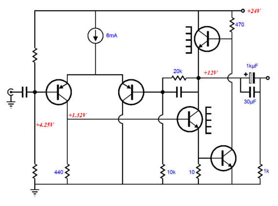
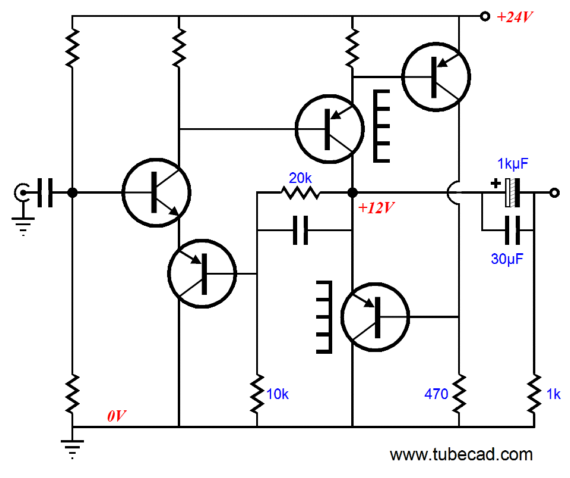
Just about every electronic device I buy now comes with a switcher wallwart power supply. And with good cause: these devices are small and cheap and universal, working with any wall voltage between 90V to 260V. The one problem with these technological wonders is that they usually are only available with mono-polar DC outputs. Which is great if the intended load is a lamp, but if you want to power an OpAmp, a bipolar power supply would be easier to work with. What is needed is a rail-splitter circuit that will effectively create a bipolar power supply out of a mono-polar DC voltage. At its simplest, all that is needed is two resistors and two large-valued capacitors. But if better performance is needed, which it almost always is with audio equipment, the following triadtron-based circuit offers hope.
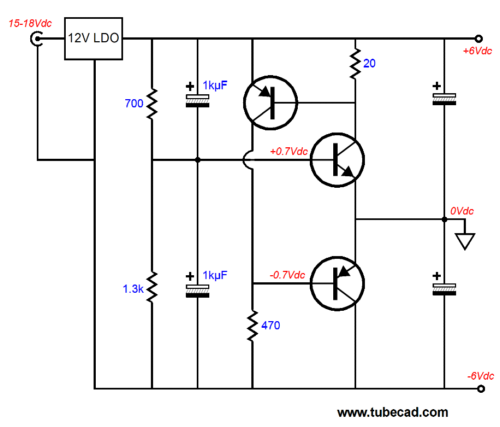
The two output transistors are nakedly connected together at the virtual ground output, ensuring a low output impedance. Once again, the topmost PNP transistor controls the bottommost PNP transistor, keeping its base voltage perfectly in line with a fixed current flow through the NPN transistor. This circuit would work well in most OpAmp applications, but would prove unsuitable in a power amplifier, because of its class-A current conduction. (By the way, the two unmarked capacitors do most the work with AC signals and they should be both large in value and high-quality in design.)
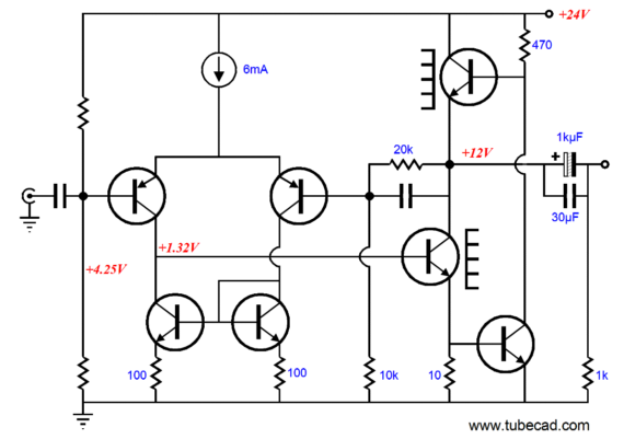
The inverted triadtron configuration results in a voltage amplifier, rather than a buffer. The example I gave last time was of a hybrid amplifier:
A completely solid-state version can be made using three NPN or three PNP transistors. Below is a simple headphone amplifier based on the inverted triadtron.
This amplifier uses a differential input stage to directly drive the NPN output transistor, which is comfortably nested in the inverted triadtron topology. The feedback loop, made up from the 20k and 10k resistors, sets a fixed gain and establishes a fixed DC voltage at the output transistor emitters. This circuit performs fairly well in SPICE simulations, but it can easily be spruced up. For example, the differential input stage can be loaded by a current mirror, which would greatly increase its gain and lower its distortion.
I know that many will be distressed by the coupling cap at the output. I, on the other hand, like the idea of protecting expensive headphones from errant DC voltages. ANd the capacitor's ESR helps buffer the output transistors from accidental shorts to ground. (Ever twist the leads on your headphones and have the sound vanish? Was because one wire opened or because the two wires momentarily shorted?) Nonetheless, converting the amplifier for bipolar power supply use is easy enough.
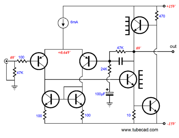
Note how the feedback loop's bottom resistor now terminates into a large-valued electrolytic capacitor. Why? In order to keep a potentially dangerous DC offset low at the output, all the amplifier's DC negative feedback must be summoned. In other words, in DC terms, the amplifier offers no gain, being more akin to a power buffer.
So did we take a giant step sideways, when we opted for the bipolar power supply? Whatever sonic degradation the large-valued electrolytic capacitor contributes will now be amplified by the amplifier's gain; and we lost the protection, to both the headphones and the output stage, that the coupling capacitor afforded so nicely. In addition, two voltage regulators will be needed, rather than the mono-polar version's si9ngle regulator. Still, the circuit shown above can be further hotrodded by cascoding the differential amplifier with a second pair of PNP transistors and by swapping out the output transistor with power MOSFETs. But I would rather travel in a different direction.
Returning to the mono-polar power supply version, we could replace the two-NPN-based differential input stage with the following configuration.
I know many are scratching their heads right now. The PNP input transistor does not help, as it knows no tube equivalent. Maybe if you turn the schematic upside down (or stand on your head), it will make more sense. When the input signal swings negative, the PNP transistor increases in its current conduction; when the signal swings positive, it decreases in conduction. Of course, we could just flip all the transistor types, as shown below.
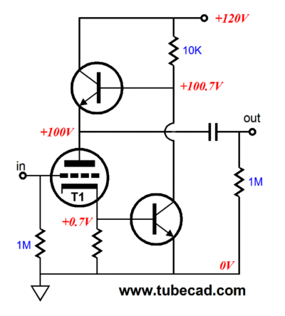
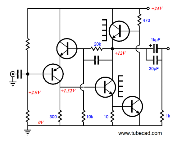
Much better. The input NPN transitor is like a triode, with positive input voltage increasing current conduction. In fact, why not swap out the transistor with a tube.
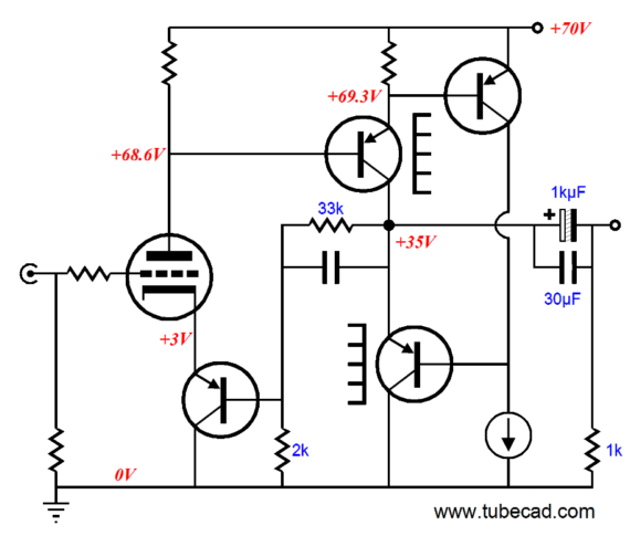
Note the increase in B+ voltage and the changes in feedback resistor values. In this amplifier, the triode's plate does not have to swing much to provoke big voltage swings from the output stage. The PNP transitor at the triode's cathode functions like a cathode resistor. In fact, the a cathode resistor could be used in place of the PNP transistor.
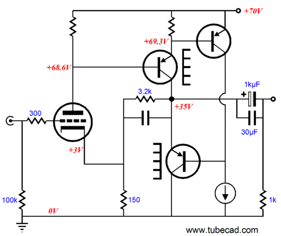
This time, note the big change in feedback resistor values. And since we are drunk with variations, let's swap out the output transistors.
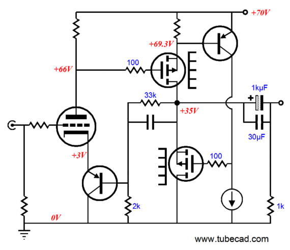
This is not a headphone amplifier, but a serious power amplifier that should put out about 60W. The problem is that the triadtron topology restricts the amplifier's operation to strict, no marketing nonsense, class-A mode, with its concomitant high idle current and great heat. Still, we can dream.
//JRB |
|
|
|
Kit User Guide PDFs
Click image to download


E-mail from GlassWare customers:
Mr Broskie,
I bought an Aikido stereo linestage kit from you some days ago, and I received it just this Monday. I have a few things to say about it. Firstly, I'm extremely impressed at the quality of what I've been sent. In fact, this is the highest quality kit I've seen anywhere, of anything. I have no idea how you managed to fit all this stuff in under what I paid for it. Second, your shipping was lightning-quick. Just more satisfaction in the bag, there. I wish everyone did business like you.
Sean H.
And
Hi John,
I received the Aikido PCB today - thank you for the first rate shipping
speed.
Wanted to let you know that this is simply the best PCB I have had in my hands, bar none. The quality is fabulous, and your documentation is superb. I know you do this because you love audio, but I think your price of $39 is a bit of a giveaway! I'm sure you could charge double and still have happy customers.
Looking forward to building the Aikido, will send some comments when I'm done!
Thank you, regards,
Gary.
9-Pin & Octal
PCBs & Kits
High-quality, double-sided, extra thick, 2-oz traces, plated-through holes, dual sets of resistor pads and pads for two coupling capacitors. Stereo and mono, octal and 9-pin printed circuit boards available.
Designed by John Broskie & Made in USA
Aikido PCBs for as little as $20.40
http://glass-ware.stores.yahoo.net/
Only $19.95
to keep track of your
tube and part collection
TCJ My-Stock DB
TCJ My-Stock DB helps you know just what you have, what it looks like, where it is, what it will be used for, and what it's worth. TCJ My-Stock DB helps you to keep track of your heap of electronic parts. More details.
List all of your parts in one DB.
Add part Images.
One-click web searches for part information.
Vertical and horizontal grids.*
Create reports as PDFs.*
Graphs added 2D/3D: pie & bar.*
More powerful DB search.
Help system added.
Editable drop-down lists for location, projects, brands, styles, vendors and more.
*User definable
For more information, please visit:
|