| John Broskie's Guide to Tube Circuit Analysis & Design |
29 February 2020 Post Number 493
To all those leaplings, Happy Birthday. I believe this is my first post on 29th of February.
Class-G High-Voltage Regulator Part-2 The sustained high current delivery pretty much eliminates our using a tube as the regulator's pass device. Pass device? What is a pass device? Okay, time to downshift. Although made up of many hundreds of parts, such as capacitors, diodes, fuses, resistors… all voltage regulators require three essential devices: a voltage reference that functions like a yardstick; a pass device that connects the external load to the B+ voltage and through which all the load current must flow; and a feedback-based control circuit that measures the output voltage and compares it to reference voltage, and then it makes the necessary adjustments to the pass device's current flow needed to bring the output voltage in line with the desired output voltage. Modern precision IC voltage references amaze. For example, for less than $2 you can buy a LM4040AIZ-10.0, a 10V voltage reference that offers a 0.1% initial tolerance and operates with just 60 µA of current flow. The next device to choose is the pass device. In days past, the vacuum tube, either a triode or pentode, worked best, as tubes can sustain high-voltage differentials. Alas, they cannot sustain high-current flow. The obvious workaround was to use many tubes in parallel, which increases the heater current demands and decreases the reliability. In addition, it's a pain to wait for the tubes to heat up before we can use the high-voltage regulator. This leaves solid-state devices.
Unfortunately, PNP transistors are voltage limited. In contrast, NPN transistors are available that offer a 1kV collector-to-emitter breakdown voltage, such as the MJW18020G, but its sustaining DC voltage is only 450V. This leaves high-voltage N-channel MOSFETs, which are both cheap and reliable. For example, the ST Electronics TW5NK100Z is an N-channel 1kV MOSFET with a 125W rating in the TO247 package and a price less than $3. All that is left is to find an OpAmp with a FET input stage that is unity-gain stable. At the low end of cost is the TL071ACP, which cost less than $1 and offers fairly low noise. This is not the place to seek the hottest, highest slewing, widest bandwidth OpAmps. In fact, stodgy is a feature, not a bug. Remember, the voltage regulator is putting out DC voltage. The last thing we want is a squirrelly OPA637.
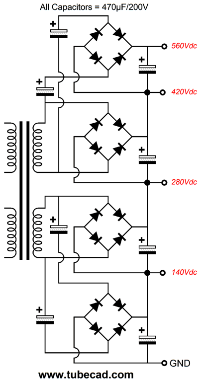
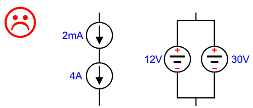
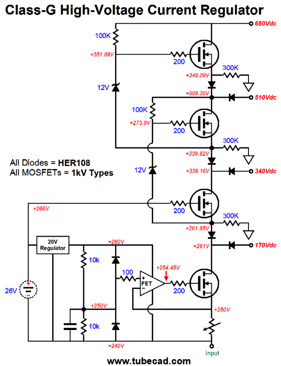
Because of my stipulation of high current delivery, I tried to devise a class-G raw power supply, wherein several high-voltage power supplies are stacked, and the pass device is powered by the next higher-voltage tap in the stack. For example, say that we set the regulator's output to 100Vdc and four 170V power supplies (each made from the rectification of a 120Vac secondary) are stacked together, making four output taps of 170Vdc, 340Vdc, 510Vdc, and 680Vdc. With a 100V output voltage, only the bottom 170V power supply would be engaged, which would limit the pass device's high-voltage exposure to only 70V from drain to source, resulting in only 35W of dissipation with 500mA of output current flow. Had we used a single 680V raw power supply, the dissipation would have been 290W. Crazy hot. Obviously, the greater the number of high-voltage power supplies stacked, the lower the needed power supply voltage and the potential worst-case dissipation. My hope was that Class-G operation would sidestep the problem of mechanical switching between power-supply-voltage taps. Well, it turns out that isn't easy to test multi-stage Class-G operation in SPICE simulations, as the SPICE engine balks at having four MOSFET stacked in series. I wasted a lot of time trying figure out why DC voltage gaps appeared in simulations, when I was absolutely convinced that they should not be possible. I finally caught SPICE red-handed, as it read out a MOSFET differential voltage of 1200V, which was impossible, as the highest power-supply voltage was 480V. By the way, this was a DC voltage reading and no inductive parts were used. This surprised me, as I have dug through the actual SPICE engine source code, which revealed that a lot of effort was put into getting the MOSFET model class to work well. In SPICE, never place voltage sources in parallel; never place current sources in series.
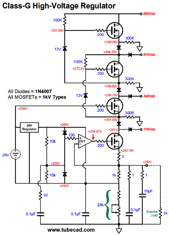
Perhaps, the MOSFET model made the same fundamental mistake that SPICE tube models make: assuming that the device is basically a variable current source, when—in fact—it is a variable resistance. In the absence of voltage, neither the triode nor the MOSFET create current flow. I then created simpler test circuits in SPICE to test each building block of the Class-G operation. After much exertion, I came up with this version of the circuit.
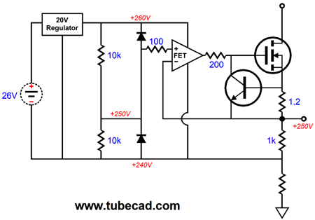
It may look similar to the version in my last post, but it holds some important differences. For example, none of the MOSFET ever completely turn off, as the 300k source resistors, which are made up of three 100k 1W resistors in series, provide a path to ground. Second, turning on the MOSFET which sits above the pass-device MOSFET no longer requires any current from the floating power supply. The top two MOSFET are turned on by the MOSFET directly below it, when needed. The net benefit is that the regulator's output voltage tracks much more linearly. An additional change is the inclusion of the 3-ohm source on the bottommost MOSFET. This resistor is a safety device, as it limits the regulator's output current in an indirect fashion. If the output were shorted to ground, the OpAmp's output would slam up to a couple volts of its positive power-supply pin voltage, which prompt a huge increase in current flow through the pass-device MOSFET, which in turn would force a larger voltage drop across the 3-ohm source resistor, limiting the maximum output current to about 4A. This is a hairy amount of current to drop into a dead short to ground, but is far less than what the MOSFET could potentially deliver. The price we pay for including the source resistor is that the MOSFET's transconductance effectively falls to just 330mA/V. If we wish to retain more of the MOSFET's transconductance, we could use an NPN transistor and a lower-valued source resistor.
The NPN transistor's base-to-emitter turn-on voltage works as a trip voltage. Assuming a base-to-emitter turn-on voltage of 0.6V and an emitter resistor of 1.2 ohms, we can conclude that once the output current flow exceeds 500mA the NPN transistor will turn on and conduct madly, which will pull down the MOSFET's gate voltage, causing the MOSFET to turn off. Concisely, we have a built in current limiter.
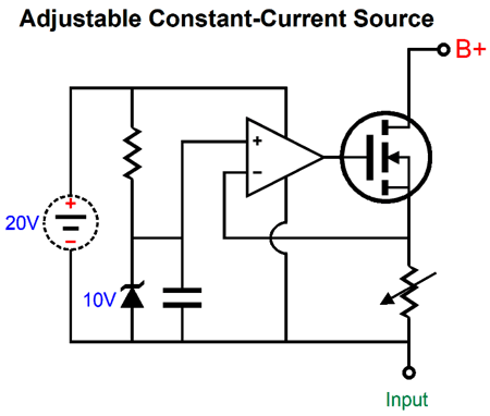
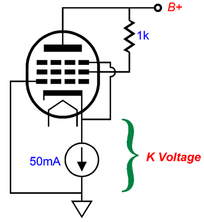
Adjustable High-Voltage/High-Power CCS Well, what if we don't take the regulator's output at the pass MOSFET's source, but at the bottom of the 1k source resistor? We no longer have a high-voltage regulator, but a high-voltage constant-current source of 10mA.
The floating power supply makes no direct connection to ground, and the external load sees a fixed 10mA flow of current and, thus, an extremely high output impedance. If we replace the 1k source resistor with a variable resistance, we create a variable constant-current source.
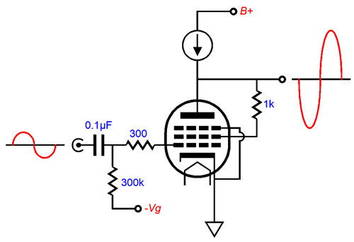
If the variable resistance falls to 10 ohms, 1A of current will flow; if it rises to 10k, 1mA. The math is simple: Current = 10V/Resistance. Okay, why would we need a variable high-voltage constant-current source? The answer is basically the same as the one for having a variable high-voltage regulator: testing. Here is an example, we have an NOS pentode and wonder what is its amplification factor (mu) would be if triode connected, but we cannot find the answer in Google searches. We could simply test the pentode with the variable high-voltage constant-current source.
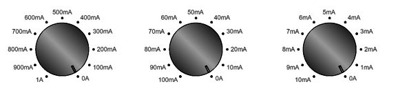
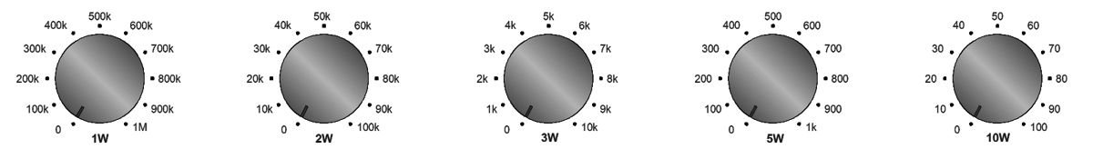
The sine-wave generator puts out 1Vpk and the oscilloscope displays plate-voltage swings of 8Vpk, which reveals the mu to be 8. Believe me, once you have a new piece of test equipment, you will find new uses for it. The interesting question is: How do we make the high-voltage constant-current source's current selectable in clean decade increments, say 100mA, 10mA, and 1mA steps? With the variable high-voltage regulator, we placed variable resistances in series; with a variable high-voltage constant-current source, we must place variable resistance in parallel. (I love how dealing with current is the inverse of dealing with voltage. Most electronic wizards think primarily in terms of voltage; I think primarily in terms of current.) The following is a three-knob goal.
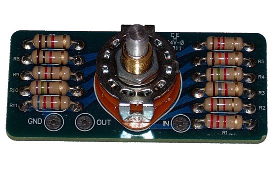
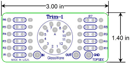
Each knob presents eleven positions, which implies a rotary switch configured as series attenuator. Well, lucky for you (and me), the GlassWare Trim-1 attenuator is just such a stepped attenuator. We leave resistor R1 out and accept the counter clockwise increments. (Actually, we could probably just solder the rotary switch to the "wrong" side of the PCB, but I like the counter clockwise increments, as they remind me of inverse world of current.)
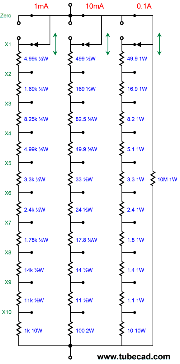
Speaking of inverse, resistors are labeled by their resistance, but they don't have to be. If our AC wall sockets delivered a fixed current, rather than a fixed voltage, resistors would probably have been labeled by their conductance, not their resistance. Think about it: resistance is a negative attribute that we express positively. A friend was once stymied by a circuit. I tried to explicate it to him, but he wasn't getting it. At one point he asked me what about the high resistance. I told him it was so high we could just ignore it. This made zero sense to him, as he saw resistance positively, which meant that high resistance was highly oppositional, fighting and hindering, much like sand in a car's engine. We can also express a positive attribute negatively. Here is a crazy example: rather than measure a man's height from the bottom of his feet to the top of his head, we used the basketball hoop's height of 10 feet as the reference, and then we measured the distance between the hoop and his head. A one foot tall man would be a giant; a four and a half foot man, Mike Bloomburg. Conductance is the inverse of resistance. Where resistance is the measure of the opposition to the flow of electric current, conductance is the measure of the acceptance or readiness to allow the flow of current. Put mathematically, Conductance (G) = 1/Resistance (R), or G = 1/R. Conductance is measured in Siemens (symbol: "S" or "mho"). For example, a 1-ohm resistance presents 1S conductance; 10-ohm, 0.1S; 100-ohm, 0.01S. Well, when working out the resistor values needed to populate three Trim-1 attenuation PCB, I had to treat the resistors as if they were labeled in Siemens. (By the way, originally, the "Siemens" was the unit of resistance, but was replaced by the "Ohm" at an international conference in 1881.)
The most important resistor is 10M shunting resistor, as it gives the MOSFET something to bite on, when all three switches are set to the zero position. Fortunately, 10V divided by 10M results in a trivial current flow, only 1µA. Most of the resistors could be 1/4W types, but I prefer dealing with 1/2W resistors. Only one resistor is high wattage, the 10-ohm resistor, which could, worst-case, dissipate 10W, as 10V would be dropped across its leads and 1A of current would flow through it, something we would never encounter with any tube circuit. By the way, if we wanted to build an adjustable constant-current source for solid-state use, we would radically decrease the stacked power supplies voltages; and we would need to decrease the reference voltage from 10V to 1V, as we could not afford to dissipate so much heat. For example, with a 1V voltage reference and a 1-ohm source resistor, 1A of current would flow, but the 1-ohm resistor would only dissipate 1W. By the way, we can no longer get away with the lowly 1N4007 in the class-G operation of the raw power-supply voltages, as a much faster rectifier would be needed, say a HER108 or a high-voltage hexfred rectifier.
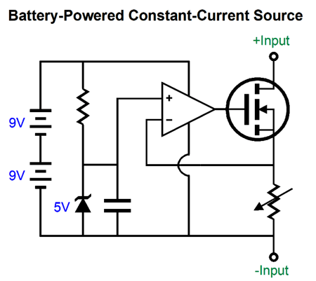
Battery-Powered Adjustable Constant-Current Source
Well, a battery-powered constant-current source is handy device. For example, we can use in place of a plate-load resistor.
Or, we can use it to match power output tubes. We measure the cathode voltage under a constant-current flow, and then we write down the voltage. After measuring all the tubes, we look for matched pairs.
Why use batteries when we could use a floating power supply made up of a transformer and rectifiers? One answer is that two 9V batteries take up a lot less room and weigh far less than a transformer. The second answer is that making transformer-based floating power supply requires care in selecting the power transformer, as we must avoid too much capacitance between primary and secondary windings. The best choice is a flat-pack, low-profile, PCB-mount transformer whose winding wrap around their own bobbins, not atop each other. But probably the most compelling answer is that batteries sidestep the problem of dealing with the house ground and signal ground. (We can still ground the CCS enclosure to the house ground whne uisng bateries.)
Resistor Decade Box One subtlety you encounter is that the resistors need not be all the same wattage. For example, say you wanted to build a simple 100W 1-ohm to 10-ohm decade resistor box for testing power amplifiers. We would wire ten 1-ohm power resistors in series and use the rotary switch contacts to select the desired ohmage. The first 1-ohm resistor must be rated for at least 100W, but the second 1-ohm resistor need only be rated for 50W; and the last 1-ohm resistor, only 10W, as it will only see one tenth the of the dissipation. In this example, the first 1-ohm resistor might be made up of three 50W 3-ohm resistors in parallel, resulting in an effectively wattage rating of 150W. We might create a sliding wattage rating. For example, the first decade of resistance, 10-ohm to 100-ohm, might be rated for 10W; the second decade, 100-ohm to 1k, 5W; the third decade, 1k to 10k, 2W; the fourth decade, 10k to 100k, 1W.
The GlassWare Trim-1 stepped attenuator and 19-inch, 1U tall, metal rack-mount enclosure would make an ideal pairing, as we would want to use a few power resistors in the aluminum heatsink incased package directly mounted on the metal bottom panel.
Each Trim-1 PCB is 3 inches wide, so we could comfortable fit five Trim-1 PCBs in the 19-in rack-mount's internal 17 inches of cabinet space. (By the way, I have bought many 19-inch enclosures from Par-Metal Products and I recommend them highly.) Five Trim-1 PCBs could deliver a range of 10-ohm to 1,111,110-ohms in 10-ohm increments. Remember, we need some space for the two output terminals. A third terminal could be provided for grounding the enclosure, either to the house ground or the circuit ground. An additional feature could be a fused output terminal—or several fused outputs, each with a different rated fuse, say 100mA, 250mA, 500mA, 1A, 3A.
Music Recommendation: Hannah Rose Platt Hannah Rose Platt is country singer from Great Britain, who was born in Liverpool, the city that gave us the The Beatles. She has a lovely voice, and she is a skilled song writer.
Tidal offer two of her albums. Give them a listen, as your ears could use a treat.
//JRB
User Guides for GlassWare Software
For those of you who still have old computers running Windows XP (32-bit) or any other Windows 32-bit OS, I have setup the download availability of my old old standards: Tube CAD, SE Amp CAD, and Audio Gadgets. The downloads are at the GlassWare-Yahoo store and the price is only $9.95 for each program. http://glass-ware.stores.yahoo.net/adsoffromgla.html So many have asked that I had to do it. WARNING: THESE THREE PROGRAMS WILL NOT RUN UNDER VISTA 64-Bit or WINDOWS 7 & 8 or any other 64-bit OS. I do plan on remaking all of these programs into 64-bit versions, but it will be a huge ordeal, as programming requires vast chunks of noise-free time, something very rare with children running about. Ideally, I would love to come out with versions that run on iPads and Android-OS tablets.
|
I know that some readers wish to avoid Patreon, so here is a PayPal button instead. Thanks. John Broskie
John Gives
Special Thanks to the Special 85
I am truly stunned and appreciative of their support. In addition I want to thank the following patrons:
All of your support makes a big difference. I would love to arrive at the point where creating my posts was my top priority of the day, not something that I have to steal time from other obligations to do. The more support I get, the higher up these posts move up in deserving attention.
If you have been reading my posts, you know that my lifetime goal is reaching post number one thousand. I have 507 more to go. My second goal was to gather 1,000 patrons. Well, that no longer seems possible to me, so I will shoot for a mighty 100 instead. Thus, I have 15 patrons to go. Help me get there.
Support the Tube CAD Journal & get an extremely powerful push-pull tube-amplifier simulator for TCJ Push-Pull Calculator
TCJ PPC Version 2 Improvements Rebuilt simulation engine *User definable
Download or CD ROM For more information, please visit our Web site : To purchase, please visit our Yahoo Store: |
|||


| www.tubecad.com Copyright © 1999-2020 GlassWare All Rights Reserved |