| John Broskie's Guide to Tube Circuit Analysis & Design |
| 09 August 2014
Cathode-Coupled Amplifier
Cathode-Coupled Amplifier
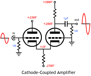
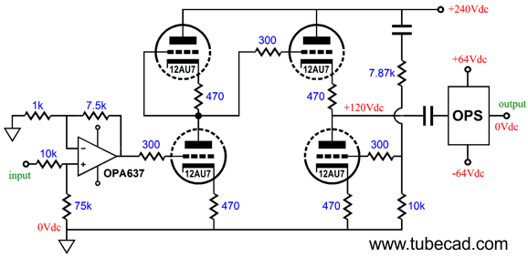
1999/tubecircuits/Common-Cathode Amplifiers Back in blog number 245, I revealed a clever variation on the cathode-coupled-amplifier that fixed three of its problems: dissimilar cathode-to-grid voltages between the two triodes, very poor PSRR, and a high output impedance. My remake solved the cathode-to-grid voltage issue, greatly enhanced the circuit's PSRR, and drastically lowered its output impedance. In a nutshell, the new circuit consists of a modified cathode-coupled input stage that uses an extra cathode resistor to equalize the current drawn by both triodes and eliminate the need for dissimilar grid voltages; the cathode-coupled input stage's output terminates into a two-resistor voltage divider, whose output cascades into a cathode follower's input. The result of these additions is that all the triode cathodes rest near ground level at idle and the power-supply noise falls out of the equation and out of the output, which now robustly presents a low output impedance.
In the above schematic from blog number 245, 6SN7 triodes are used throughout, but in the new GlassWare Cathode-Coupled stereo PCB, three noval tubes are used. Why the change? Two reasons, the noval tubes and their sockets are smaller and a far greater number of different noval tube types are available. (Who knows, maybe some time in the distant future, I will create an octal version, which will be much larger, say 8 inches wide and 6 inches deep. Do not hold your breath.)
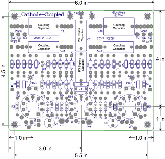
No doubt, the first thought to cross your mind upon seeing the above PCB layout is "Why are there so many more parts than in the schematic?" The answer is that the PCB, being a stereo design, holds two channels of cathode-coupled amplifiers; and I purposely used multiple resistors in series and in series-parallel in place of single resistors. Why? Two reasons: greater potential heat dissipation and less voltage-induced distortion. Obviously, four 10k/1W resistors in series-parallel will be able to dissipate four times more heat than one 10k/1W resistor, while still presenting 10k of resistance. What isn't obvious is that they will exhibit less distortion. In general, we tend to ignore resistor-induced distortion, and with good cause, as it tends to be very small indeed—but not altogether absent. Under extreme current flow or high voltage, the resistor's distortion increases. With typical tube-based, small-signal circuits, which usually run in class-A, it's the voltage-induced distortion that we need to worry about.
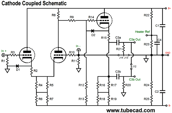
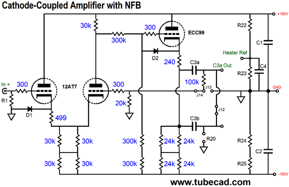
In the above schematic of the new GlassWare Cathode-Coupled PCB, we see the input stage's and output stage's cathode resistors replaced with a four resistor combination in series-parallel, R4 - R7 and R16 -R19. In addition, the two-resistor voltage divider is made up from three resistors, R9, R12, and R13. Diodes D1 and D2 are protection devices that conduct only at startup, when the tubes are cold and haven't begun to conduct current—or when a tube is missing from its socket. Without these diodes, the cold cathode-coupled input triode would see the full negative rail voltage on its two cathodes and 0V on its grid; not good. And it would be even worse for the cathode-follower output tube, as its cathode would be at the negative rail voltage and its grid at half the positive rail voltage! One hell of a wake-up call. Imagine a bipolar power supply of ±200V, so the output triode's cathode-to-grid voltage would be 300V! So, what's the big deal? The big deal is that the electrostatic force between the cathode and grid, which are nearly touching, would be so great that chunks of the cathode coating would peel away and fly up to the plate. Not good. But once the tube are hot and conducting, the diodes become reversed biased and cease to conduct, thereby falling out of the circuit.
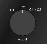
My signature two sets of coupling capacitors are present on the PCB. Why? I will say it again: I love being able to exert some sonic control on my music playback. All coupling capacitors exhibit slightly different sonic overlays. Many recordings are either too bright or too thin or too dull or too fat sounding. But by using a coupling capacitor with an opposite sonic character, the result will be closer to neutral. (In my own cathode-coupled build, I am using old Vitamin Q PIO and 1kV CDE polypropylene coupling capacitors, but I plan on replacing the polypropylene capacitors with some American Teflon capacitors, as I want a bigger sonic contrast between the coupling capacitors.) Sorry, John, but I am an absolute-sound kind of guy; if a coupling cap isn't absolutely perfect, I don't use it. Well, even if you have found the perfect, the very absolute, coupling capacitor, you could still benefit from the two-coupling-capacitor setup. How so? Use two values of the perfect coupling capacitor, say 1 µF and 0.33µF. Why? With a Select-C rotary switch, you could place both in parallel for normal listening, but use only the 0.1µF coupling capacitor for late-night or early-morning listening, when you do not wish to bother others with deep-bass rumblings.
Or, imagine that some LP is so warped that it is causing your subwoofers to do push-ups against the back wall; well, you could choose the coupling capacitor that imposed a 30-Hz cutoff instead of the bigger coupling capacitor that went down to 3 Hz, say 1µF and 0.1µF, which would function as a rumble filter of sorts.
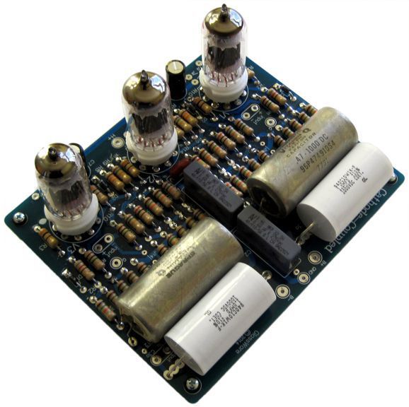
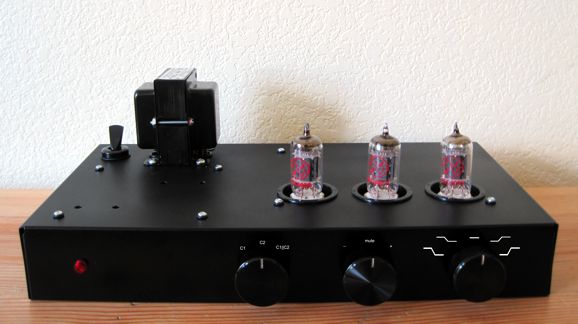
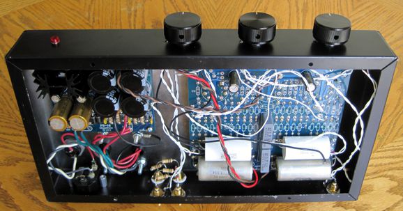
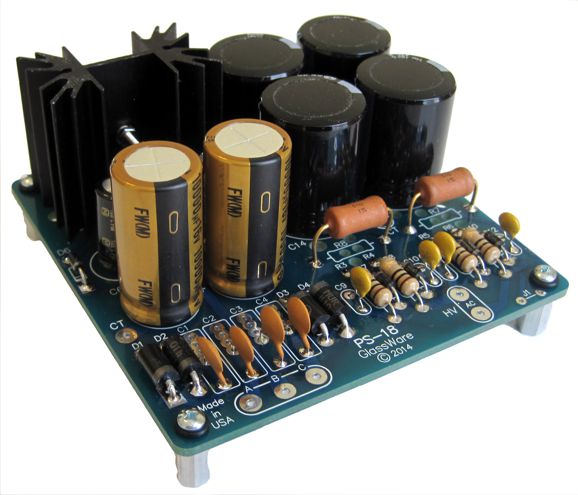
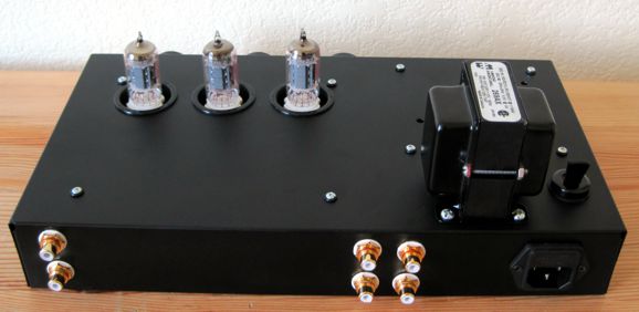
What you see above is my own implementation of the new GlassWare Cathode-Coupled PCB. I drilled, punched, and painted a small aluminum Bud box, 2in tall, 13in wide and 7in deep. Yes, it's cute—too cute, alas. The PCB was assembled with most of the parts on the topside, such as the tube sockets and resistors, but all the capacitors were soldered to the bottom side, as I like having the tube protrude from the enclosure top, like three missiles leaving their silos.
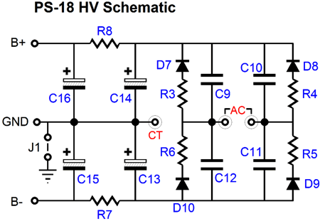
The power supply is a PS-18 high-voltage, bipolar design with a regulated heater power supply.
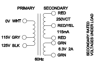
I configured the heater power supply as a voltage-doubler circuit, so that a 6.3Vac heater winding could develop a regulated 12Vdc output voltage for the three 12AU7 tubes. The power transformer that I used was the tiny Hammond 269AX type.
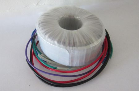
Although this transformer is cute, I wish that I had used a bigger transformer, as it makes too much mechanical noise. (Using the 125Vac input tap, rather than the 115V tap, helped, and I will add four long, non-magnetic screws to hold the assembly more tightly together, but what a pain, as the transformer should have come with six screws, not just two. I have such mixed results with Hammond transformers.)
As an alternative, Antek offers a 100VA, 400Vac CT toroidal for only $34.50, an absolute bargain compared to the Hammond transformer, the AS-1T200, which also holds two 6.3Vac @3A heater windings, which could be wired in series, thereby creating a 12.6Vac @3A secondary. The 400Vac CT rectifies up into ±280Vdc, which the RC filters (C15 & C16 and R7 & R8) on the PS-18 can drop down to ±200V or ±250V.
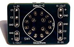
Interestingly enough, none of the three knobs on the front of my design are a volume control. Instead, I used a GlassWare Tilt Control, a Select Phase, and a Select-C switch. So where's the volume control? I didn't need a volume control, as my DAC can control the volume on its own. I did, however, want more sonic control. (I wish that I had room to add a stereo-mono blend control, as I have been listening to many early Beatle recordings. Way too much sepa ration.) Undoubtedly, 99% of Hi-Fi builders would not use my arrangement, opting instead for an input selector switch and a volume control.
Since this cathode-coupled line stage was meant to partner only with my DAC, only one input is present, the pair of RCA jacks at the left. So what do the four RCA jacks on the right do? I need two sets off output jacks, as I run two sub-woofer amplifiers. (I soldered in place -6dB two-resistor attenuators on the sub outputs.) The Tilt Control is a gas. I only use it on one in ten recordings, but it makes all the difference in my musical enjoyment. Most often, I tilt the sound towards the bass, particularly with many 1970s recordings; but more than a few times, I have tilted towards the highs. Well, I was recently reading an excellent comparative review by John L. Wright of the many classical CD recordings of Janáček’s Glagolitic Mass at musicweb-international.com. Deep within the long review, we find this passage:
This perfectly illustrates the benefit of a tilt control. Yet, how many high-end stereo systems include one? It might be rude of me, but I will quote myself from my article on the Missing Sonic Controls.
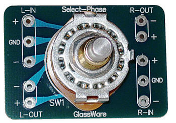
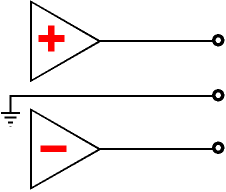
The surprisingly effective sonic control is the phase switch, with a mute position at its center.
I do believe that playback polarity is important, but I am often too lazy to fiddle with the phase. A mistake. The difference is subtle and only hearable after a few seconds of silence, which allows the ear to readjust to the phase reversal. The result is not a tonal change, but a subtle change in perspective, in sonic presentation, with one polarity setting just sounding more correct. (Ideally, I would like to catalog my preference for each recording and then store that selection in a database, so when the track is played back via the computer, the phase selection is made by software rather than by me.) With the GlassWare Cathode-Coupled PCB, two inputs per channel are offered. Thus, it is easy to select a phase by choosing an input, while grounding its partner.
This brings up the topic of balanced-to-unbalanced conversion. The GlassWare Cathode-Coupled design can accept a balanced input signal, yet it puts out an unbalanced, single-ended output signal. Its CMRR is not however, nearly as good as offered by the Unbalancer circuit, but then you may not need a high CMRR. At the other extreme, if you are the adventurous type, you might want to experiment with adding a negative feedback loop to the Cathode-Coupled Amplifier. All that is needed is to use jumper J12 and J14, not J13, which causes resistor R21 to become a two-resistor voltage divider with resistor R11. Of course, in order for negative feedback to do its magic requires extra gain to fuel the feedback process, which means that a 6CG7 or 12AU7 would be a poor choice as an input tube, as they offer too little signal gain. On the other hand, the 12AX7 would be excessively dragged down by the two-resistor voltage divider that feeds the cathode follower. Thus, the best choice might be the 12AT7 as the input tube and an ECC99 as the output tube.
In the above schematic, the rail voltages are +150Vdc and -150Vdc. This would be a good lower limit; I would be more likely to use +250Vdc and -250Vdc instead, which is quite hot—but would probably sound just stellar. In SPICE simulations, with the +250Vdc and -250Vdc rail voltages, the output impedance came out at 100 ohms and the gain was +12dB, with very little distortion; but the key improvement was its fine PSRR, which in SPICE simulations came in at -60dB. Mind you, the ECC99 will get plenty hot, as it will draw about 10mA with 250V rail voltages. (The entire stereo line stage will draw 40mA, which against the 500V of power-supply voltage equals 20W of heat! This is not your father's cathode-coupled-amplifier (or your brother's grounded-grid amplifier ;). What do I think of my more modest all-12AU7-based effort? First of all, you cannot imagine how I wish that I were less capable. What!? Really, John! Let me explain, but in my typically roundabout way. The greatest English writer ever, William Shakespeare, admitted that he envied other men's talent, along with their looks, learning, and friendships, in his Sonnet 29:
Then, hundreds of years later, in 1846, Soren Kierkegaard wrote about modern envy in his book, The Present Age, where he writes about an age when other men's gifts are not envied:
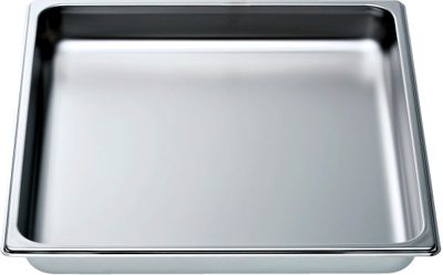
Well, I envy those who cannot fix broken cars, cannot assemble stereo gear, cannot cook, cannot kill zombie hoards... as they just toss or give to others to repair their irreparable items, irreparable by them that is. In contrast, I can do neither, neither throw away or handoff to others to repair, as I find very little to be irreparable or un-assemblable by me. So, much in the same way that car mechanics always own cars that do not run and hair stylist often have bad hair cuts, my basement is filled with electronic parts and stereo equipment that I could repair or assemble—if I had the time and the will. Well, that cute little enclosure was far too small. It would be easier to vanquish a hoard cannibalistic zombies than it was to assemble this cute piece of tube gear. (By the way, are there any vegan zombies?) Yes, I did get everything to fit, but just barely. Had the Bud box been three inches deeper and four inches wider, the assembly would have been ten times easier. Here is my recommendation, which few will follow: buy a cheap, but sturdy cooking pan, the type you would bake brownies in.
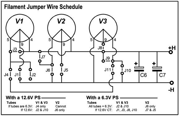
Next, assemble your tube project in it. Quick and dirty is the goal. Forget about looks, but not safety. Fiddle with the design, adjust positions, take notes, spot potential problems, measure performance, make upgrades as needed... Then, when you are absolutely sure and satisfied, build the real project within a fancy enclosure, using all your parts. When you are done making the transition, like a butterfly's old cocoon, toss the hole-filled cooking pan in the recycle bin. This is the smart path to follow, but even I—and I do know better—fail to do so. In short, it was a pain to put this cute project together, which ill disposed me to like the resulting sound. Second, the Hammond transformer disappointed me by making so loud a mechanical buzz. Yet, several hours of listening (and placing a heavy power transformer atop the Hammond transformer) have erased most of my ill will towards the cute project. Indeed, the more I listen, the more I discover that I like. The GlassWare Cathode-Coupled line amplifier produces clean and quiet gain, allowing many subtle pieces of sonic information to pour forth, especially sonic imaging information. So far, I am quite pleased with the JJ long-plate ECC802 (12AU7) tubes, but at some point I will dig out some RCA NOS clear tops and some very old NOS Amperex, Telefunken, and Tungsol 12AU7 tubes. One design issue we encounter with any cathode-coupled-amplifier is the triode's maximum plate voltage, as both one input triode and the cathode-follower triode will see the full positive rail voltage. The 12AT7 (6201, CV10662, CV455, CV8154, CV9859, ECC81) limit is 300Vdc, as it is for the 12AU7 and 12BH7; the JJ ECC99 plate voltage limit is a whopping 400Vdc. For some twin triode tubes, however, the limit is 250Vdc. The JJ E88CC's plate-voltage limit is confusing, as its data-sheet list several maximum plate voltages, with the lowest being 220Vdc. Other data-sheets specify a 130V plate-voltage limit, which I am sure applies only to cascode operation, as both triodes share the same heater connection, as to high a cathode-to-plate voltage for the bottom triode will result in too great cathode-t0-heater voltage for the top triode. For most setups, a 6CG7 or 12AU7 will be chosen as both the input and output tubes. A 12BH7 or JJ ECC99, however, would make a better output tube. Sadly, the excellent 5687 cannot be used, because of its oddball pin-out. By the way, the heater setup is quite flexible on the PCB.
As you can see, the two input tube heaters can be placed either in parallel or in series, so two 6CG7 input tubes and one ECC99 output tube can share either a 6.3V or 12V heater power supply. But three 6CG7 tubes could not be used with a 12V heater power supply. The GlassWare Cathode-Coupled PCB and kit are available now at the GlassWare-Yahoo store. The PCB comes with a 16-page user guide and is only $29. Dirt cheap for such a high-quality, USA-made board, in other words. The chef's 12 by 9 inch cooking pan, on the other hand, will set you back $18 at Target.
More 3-Technologies Hybrid
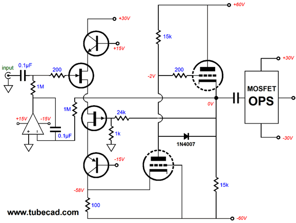
While this alternate suggestion offers much to like, its glibness bothered me. Well, after more thought, the following design overview came to me.
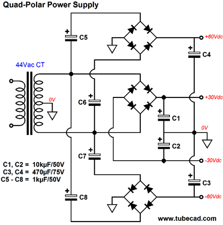
The two FETs define a bastode circuit, a vertical differential amplifier in other words. The two transistors cascode the FETs, which protects the FETs from the relatively high voltages. The leftmost triode is configured as a grounded-grid amplifier, which receives its input signal at its cathode. The rightmost triode is configured in a cathode-follower circuit, which both shields the grounded-grid amplifier's output from the output stage and offers a low output impedance. The MOSFET-based output stage delivers lots of current without creating any voltage gain. The lowly 1N4007 diode is the hero of the day, as protects the triodes and FETs at start-up. The MOSFET-based output stage would provide about 36W into 8-ohm loads. (I will put up with less power output, if I can get away with only two output devices.) The two triodes form a CCDA circuit and would, unlike the typical CCDA setup, exhibit a stellar PSRR, as first tube stage will split the two power-supply rail noises, which should null, as they should be be equal in magnitude, but out of phase. The DC servo at the input does not correct the DC offset voltage at the amplifier's output, but at the cathode-follower's output; much in the same way, the negative feedback loop only extends up to the cathode-follower's output. So, yes, this hybrid power amplifier does use a feedback loop, but not a global one. Thus, this amplifier is a double hybrid of sorts, which uses FETs, transistors, tubes, and MOSFETs; feedback and no global feedback. The power supply would be easy to assemble, as the four rail voltages can be had from one center-tapped secondary:
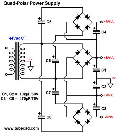
If more voltage is needed for the tube stage, then the following variation would work well.
Note where capacitors C3 & C4 terminate and how the bridge rectifiers are attached. Also note the change in parts values, particularly the voltage ratings.
Next Time
For those of you who still have old computers running Windows XP (32-bit) or any other Windows 32-bit OS, I have setup the download availability of my old old standards: Tube CAD, SE Amp CAD, and Audio Gadgets. The downloads are at the GlassWare-Yahoo store and the price is only $9.95 for each program. http://glass-ware.stores.yahoo.net/adsoffromgla.html So many have asked that I had to do it. WARNING: THESE THREE PROGRAMS WILL NOT RUN UNDER VISTA 64-Bit or WINDOWS 7 & 8 or any other 64-bit OS. I do plan on remaking all of these programs into 64-bit versions, but it will be a huge ordeal, as programming requires vast chunks of noise-free time, something very rare with children running about. Ideally, I would love to come out with versions that run on iPads and Android-OS tablets.
//JRB |
I know that some readers wish to avoid Patreon, so here is a PayPal button instead. Thanks. John Broskie
Kit User Guide PDFs
E-mail from GlassWare Customers
Aikido PCBs for as little as $24 http://glass-ware.stores.yahoo.net/
Support the Tube CAD Journal & get an extremely powerful push-pull tube-amplifier simulator for TCJ Push-Pull Calculator
TCJ PPC Version 2 Improvements Rebuilt simulation engine *User definable
Download or CD ROM For more information, please visit our Web site : To purchase, please visit our Yahoo Store: |
|||


| www.tubecad.com Copyright © 1999-2014 GlassWare All Rights Reserved |