| John Broskie's Guide to Tube Circuit Analysis & Design |
|
30 December 2019 Post 488
Happy New Year!
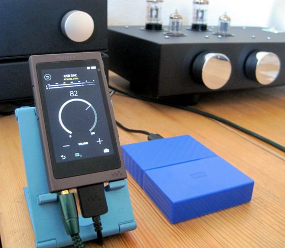
The two-faced god at once looked back and forward. On January 1st, we look forward to meeting our goals; but on December 31st, we should look back to those events and things we delighted in most. At least that is what I like to do. In terms of audio, I took stock of which audio products purchased delivered in 2019 produced the greatest enjoyment for dollar spent. I quickly came up with four noteworthy audio devices. The first is the portable handheld 10,000mA USB charger, model AT1255, from Atomi Qi USB that I mentioned in post 460. I run my standalone DAC from this floating power supply and I noted a 10% increase in sound quality, which considering its $30 cost is a huge bargain. I have seen new 20,000mA-hour USB batteries, but at twice the cost.
The second audio device of note has to be my Sony Experia XA2 Ultra smart phone, as it sounds so much better than my previous phone, off the charts better. I read that Sony had put extra effort into getting good sound on their phones, so I took a chance; the bet paid off handsomely. In fact, I listen to Tidal MQA music with it, as it unfolds the MQA files. The only complaint I have encountered concerning the phone is its large size, but as I have both big hands and poor eyesight, it see its large size a feature.
My third choice is a 4TB small portable hard-drive from Western Digital, model My Passport. I have loaded my entire computer library onto the drive, so I no longer have to rely on WiFi streaming from my main computer. In addition, it is a handy back-up drive of my music collection. To be honest, I wish I had bought the equivalent drive from Seagate, as the Seagate drives are both smaller and quieter and sleeker looking. (I know, as I own a few of them.) The WD drive, however, was on sale, and I took a chance.
The last audio device is my purchase from 2018 not 2019, my Sony Walkman NW-A45 Hi-Res 16GB personal-music player. I, however, did find a new use for the NW-A45 this year. After installing Foobar2000 on my laptop and attaching my WD portable hard-drive, I set about doing some serious headphone listening with my dynamic and electrostatic headphones. My laptop, a Lenovo IdeaPad S340, boasts of its powerful audio amplifiers (2W) and its high-quality Dolby-Audio circuitry and software. Nonetheless, although the sound feeding my headphones from it directly or through my tube headphone amplifiers was far better than any previous laptop I have owned (or I have heard), it didn't sound nearly as good as the sound produced by my Sony phone, either directly or cascading through tube amplification.
I thought about buying one of those small colorful Audioquest Dragonfly USB DACs, when I remembered that my Sony Walkman NW-A45 doubles as an USB DAC. Indeed, it can accept DSD and 192 kHz/24 bit FLAC files. Well, it works beautifully with my tube headphone amplifiers. Its digital volume control is easy to use, as are the NW-A45's features, such as its equalizer and reverb settings. Not a lot of money spent, yet lots of listening pleasure derived.
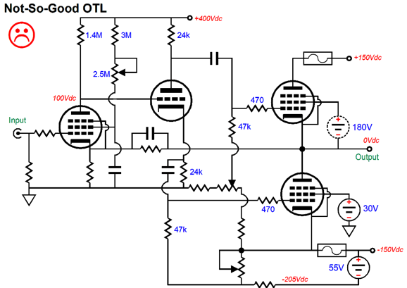
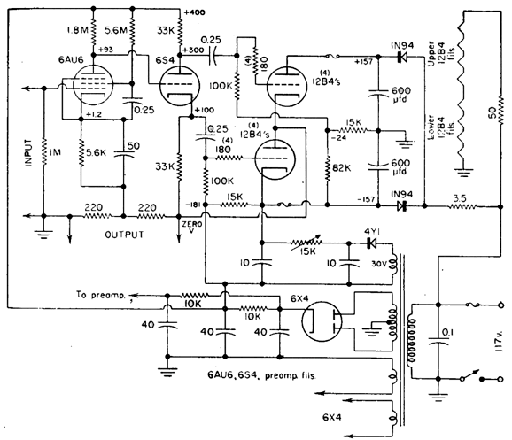
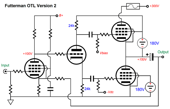
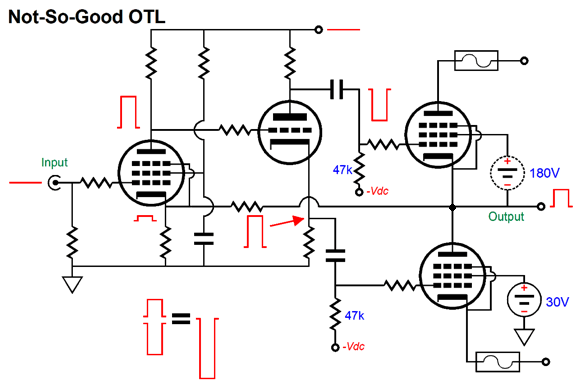
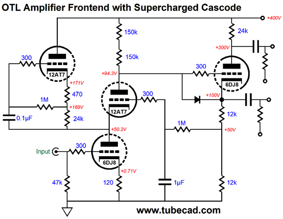
Renovating An OTL Amplifier How many problems can you spot? Here is a more-detailed view of the same circuit.
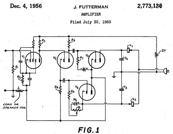
It looks much like a classic Futterman design—minus Julius Futterman's insightful contribution. Futterman's 1956 patent, US2773136A, spells it out:
His novel method was to return the output signal to the split-load phase splitter so that the top and bottom output tube would the same cathode-to-grid voltage swings, in spite of the top output tube's cathode swinging up and down with the output signal. Returning to Futterman's patent,
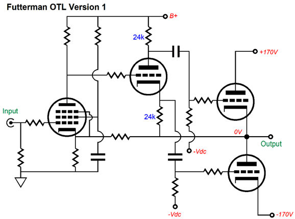
Here is the actual schematic of Futterman's OTL amplifier.
In short, the top and bottom output tubes cannot see the same magnitude of input signal, save for the special case of when the output stage is driving a near-zero-ohm load. When the output stage is effectively grounded, both output tubes' cathodes are also effectively grounded. With 8-ohm loudspeaker loads, however, the top output tube must see a far larger input signal than the bottom tube, as the bottom output tube's cathode is effectively grounded, while the top cathode swings up and down with the output signal.
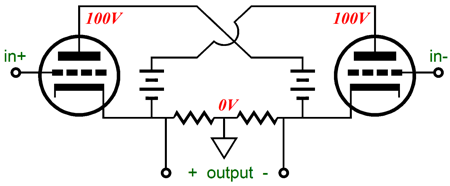
Note that the circlotron nicely sidesteps this problem, as both output tubes see equal but anti-phase voltage swings at their cathodes, so both output tubes must see equal but anti-phase input signals.
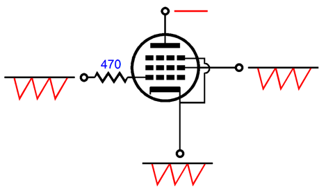
Futterman employed two different arrangements of returning the output to the split-load phase splitter: either at the bottom of the cathode resistor or at the top of the plate resistor.
Above, we see the OTL's output delivered to the bottom of the cathode resistor. Below, we see the OTL's output delivered to the top of the plate resistor.
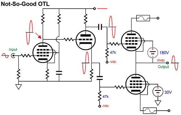
Interestingly enough, both arrangements yield the same results: they increase the output stage's gain and output impedance. A high-output-impedance OTL? The output impedance is lowered ultimately by the negative feedback loop, which uses the higher gain to further power the feedback mechanism, resulting in lower output impedance. Effectively, both output tubes function as grounded-cathode amplifiers, neither as cathode followers (something Futterman got wrong in his patent description). Pentodes present extremely high plate impedances, so open-loop output impedance would naturally be extremely high. In contrast, triodes present a relatively low plate resistance, so if the two output pentodes were replaced by two output triodes, the open-loop output impedance would equal rp/2. Let's return to the OTL design that needs help and let's remove the negative feedback loop, which will allow us to better see the signal relationships.
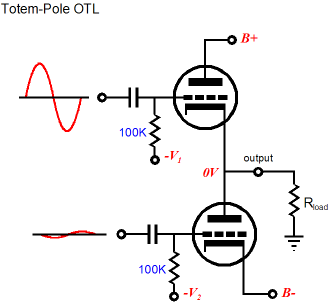
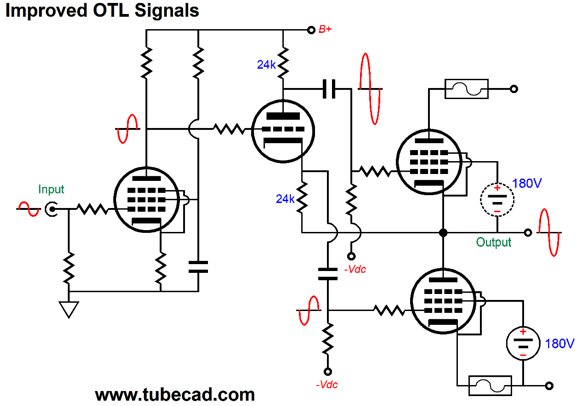
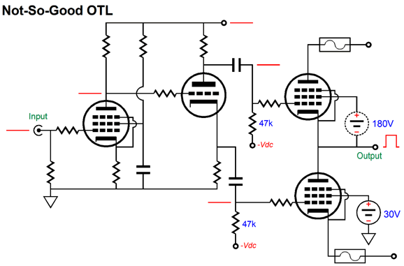
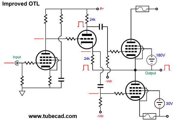
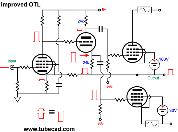
The pentode-based input stage uses a crazy high plate resistor value, so as to create as much signal gain as possible. This greatly amplified signal is passed on to the split-load phase splitter, whose ultra-high input impedance prevents any dragging down of the input stage. The signal emerges in phase at the cathode and inverted at the plate. Both signals are equal in magnitude, but are in anti-phase. The top output tube acts in this topology, unlike the top tube in the Futterman OTL, as a cathode follower and its cathode follows the signal at its grid. Thus, the actual grid-to-cathode signal must be less than the signal leaving the split-load phase splitter. In contrast, the bottom output tube's grid-to-cathode signal does equal what leaves the split-load phase splitter and is far larger than what the top output tube sees. In other words, the bottom tube is greatly overdriven. For a simple thought experiment, imagine replacing the output tubes with high-voltage MOSFETs, MOSFETs with transconductances ten thousand times greater than the output tubes. For example, a transconductance of 10A/V is considered just so-so for a modern MOSFET. To produce 1W of power into an 8-load requires 4Vpk of output voltage swing. If we deliver 4Vpk to the bottom MOSFET's gate, it will try to conduct 40A of current. In contrast, the top MOSFET effective transconductance is only 123mA/V, due to the degeneration caused by the 8-ohm load, so the top MOSFET is grossly under-driven. But, John, people say that they like the sound form this OTL. Sure, but people say many crazy things—that is our species' specialty. Besides, what is wrong with obtaining even better sound? What is going on here is that the high gain and, thus, high negative feedback work to restore signal purity. In the Futterman design, the feedback has far less work to perform. In addition, the Futterman arrangement of the split-load phase splitter allows more signal headroom, as the bottom output tube's require input signal is much smaller than the top output tube's. But when we needlessly overdrive the bottom output tube and underdrive the top output tube, we pointlessly waste cathode-top voltage in the split-load phase splitter. Let's now apply this fix to the OTL and compare the relative signals through the amplifier. The input stage now delivers a smaller output signal and the bottom output tube sees this smaller signal, but the top output tube sees this signal inverted and amplified. If we subtract the output signal from the input signal the top output tube sees, we get the same magnitude of signal as the bottom output tube. Far better. Now let's look at the output impedance with no negative feedback loop on the original poor OTL design. An externally applied positive voltage pulse is forced into the OTL's output. The bottom output pentode is indifferent to the pulse, as its plate impedance is staggeringly high. The top output tube, however, responds to the pulse, as its grid remains fixed at its bias voltage and its cathode has been forced more positive, so the top pentode reduces its current conduction, which bucks the positive pulse. In other words, this is a half-hearted response, as the bottom output tube does nothing. In contrast, the Futterman arrangement produces the following response. The positive pulse relays through the split-load phase splitter's triode up to its plate, which cause the top output tube's grid to see positive pulse, so no net change in grid-to-cathode voltage occurs, so the top pentode's current conduction remains unchanged. Once again, the bottom output tube ignores the positive pulse. Neither output tube responds, so the effective output impedance is close to infinity. Before you are tempted to say, "but John," let me point out that the negative feedback loop will prompt both output tubes to counter the pulse by both tubes altering their current conduction to buck the pulse, with the top tube shutting off and the bottom tube fully conducting. Here is the original bad OTL schematic with the negative feedback loop in place. The negative feedback loop returns a portion of the positive pulse to the input stage's cathode, where the pulse becomes amplified in phase at the plate resistor. The grounded split-load phase splitter then deliver this amplifier pulse in two phases. The top output tube sees the same magnitude pulse as the bottom output tube. But as the top output tube's cathode is forced more positive, the effective negative counter pulse is far larger than what the bottom output tube sees. In this case, the top output tube is overdriven, while the bottom is underdriven. Now, let's compare this to the Futterman arrangement. The input stage performs the same amplification of the positive pulse, but the split-load phase splitter delivers a radically different set of output signals. The externally applied pulse not only forces the top output tube's cathode positive but also the bottom of the split-load phase splitter's cathode resistor. The result is that the inverted pulse is much lower in magnitude compared to what the non-inverted pulse leaving the cathode. Yet, bottom output tubes see the same magnitude of countering pulse signal, as the top output tube's cathode was forced positive, so effectively the small negative pulse at its grid is much bigger. Okay, we have cleaned up the biggest problem with this OTL design, but a few smaller problems remain. The first is that the PSRR is not all that it could be. Note that in the Futterman design that uses output pentodes, the bottom output tube's cathode is grounded and a monopolar power supply is used. In the poor OTL design, a bipolar power supply is used. This arrangement saves us the need for a large-valued output coupling capacitor, but it does muddy the waters. In Futterman's design with a bipolar power supply, he made no attempt to rectify the PSRR problem other than employ gobs of negative feedback. In fact, he points out in his patent that with 60dB of NFB, 1 volt of ripple will reduce to 1mV at the output. Nonetheless, the problem remains, even with 60dB of negative feedback. Here is why: all power amplifier power-supply rails that are not voltage regulated contain a healthy amount of ripple. The higher the bipolar power supply rail voltages, the greater the ripple. But in this OTL design, no attempt was made to address the problem of the ripple on the negative power-supply rail. Problem, what problem? This ripple is treated by the output tube as signal. Remember that a pentode's cathode actually offers a transconductance equal to its grid. In other words, since this pentode's grid and screen-grid do not see this ripple, the pentode varies it current conduction in response to the ripple. In contrast, the top output pentode's plate is indifferent to the ripple at the positive power-supply rail. This topology just gives the negative feedback more mess to clean up. If the bottom output pentode's grid and screen-grid saw the same ripple as its cathode sees, then the pentode would prove as indifferent to the negative power-supply rail ripple as the top pentode is to its ripple.
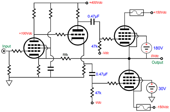
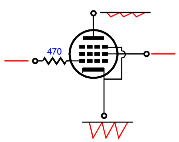
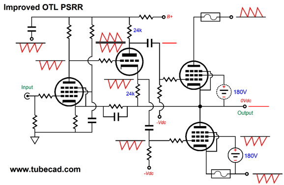
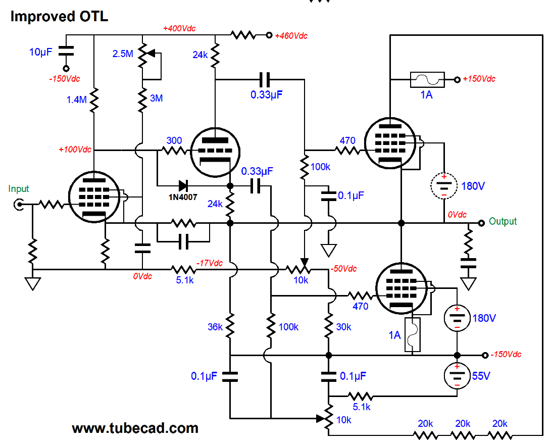
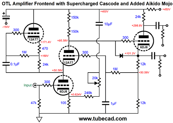
Okay, how do we fix this problem? This will be tricky, as we want to purposely pollute the signal going to the bottom output tube, but not sully the signal going to the top output tube. Here is my solution. We inject 100% of the negative power-supply rail noise into the input stage's and split-load phase splitter's shared B+ voltage via the decoupling capacitor, which is in fact a coupling capacitor in this application, to the negative power-supply rail. The input pentode offers very little PSRR, so the negative power-supply noise passes freely to the split-load phase splitter and then out its cathode output to the bottom output tube's grid. You might imagine that the negative power-supply noise will emerge inverted at the phase splitter's plate. It doesn't. What happens is that it tries to, but the top of the plate resistor is terminated into 100% of the negative power-supply noise, so the two anti-phase signals cancel, just as -1 and +1 equals 0. In other words, the plate voltage wants to swing up, but the top of the plate resistor is swinging down by and equal amount, then it wants to swing down, but the top of the plate resistor is swinging up. The screen voltage no longer comes for a 30V ground power supply but from a 180V power supply that is referenced to the negative power-supply rail, so all the negative power-supply noise is delivered to the bottom output pentode's screen-grid. It's true that the screen grid doesn't offer as much transconductance as the grid or cathode, but still offers some, so why make matters worse. One of the remaining problems with the original OTL is the lack of a grid-stopper resistor for the split-load phase splitter. The solution is to add one, preferably a non-inductive type, such as carbon-composition or bulk-foil. Additionally, at startup, the phase splitter's triode will see 0V at its cathode and +400V on its grid. Not good, as we risk damaging the triode due to cathode stripping. The workaround is to add a safety diode, say a 1N4007, which will be forward biased when the triode's cathode is 0.7V more negative than its grid. Another problem, but one not shown in my clarified schematic is that many potentiometers are used as rheostats. So what, they are the same thing, aren't they? No. They differ. Rheostats are designed to vary the current flow in a circuit and are made far more robustly as a result. For example, rather than using thin coating of resistive film they use a thick wire-wound resistive wire and strong scraper that can sustain continued DC current flow. I much prefer do limit potentiometers to AC signal adjustments only, as I have suffered too many flaky potentiometers in my life. The last problem, which isn't the least important, is that the fusing is not optimal. We use fuses to protect tubes, transformers, and loudspeakers. In the original OTL arrangement, when the positive power-supply rail fuse blows, the bottom output tube still sees the same bias voltage, which means that it will pull the output voltage negatively. What we want instead is for the bottom tube to shut off when the positive fuse opens. Conversely, when the bottom fuse blows, we do not want what will happen with the original design: the top output tube's grid will see a big positive voltage swing up to 0V, so the tube will draw a current only limited by the loudspeaker's woofer's resistance. Not good. We need to keep the top output tube's bias circuitry on the other side of the negative fuse. Here is the rework, which is still missing a few bells and whistles.
Click on schematic to see enlargement
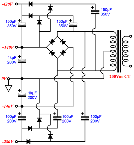
Note that when the positive fuse blows, the bottom output tube's grid bias falls; when the negative fuse blows, the top output tube's grid see its bias voltage remain in place. (Ideally, it would fall enough to shut off the top tube's current flow, but staying put is a step in the right direction.) In addition, note the 36k resistor that bridges the -150V power-supply rail to the 24k cathode resistor. This resistor unloads the bottom output tube, as it provides a current path from the split-load phase splitter to the negative power-supply rail, which the bottom output tube would otherwise have to provide. We could borrow the power-supply topology I created for the Brazilian OTL, back in post 416, except that we would use a slightly higher secondary voltage.
Missing are the two 180Vdc power supplies needed for the pentode screens. The screen do not draw all that much current, so small power supplies could be built. The input pentode and split-load phase splitter combined only draw 5mA, so the 10µF coupling capacitor to the negative power-supply rail might prove adequate. The problem is that this capacitor should be rated for at least 600V. Two 400V electrolytic capacitors can be placed in series with shunting 300k power resistors to ensure equal voltage division. (I would bypass the two capacitors with a single 1kV 1µF film capacitor.) Only one potentiometer sees a sustained DC current flow; the rest should be DC current free. The added 0.1µF capacitors that attach to the potentiometer scraper are there to both filter away power-supply noise and to prevent jumps in bias voltages when the scraper momentarily loses contact.
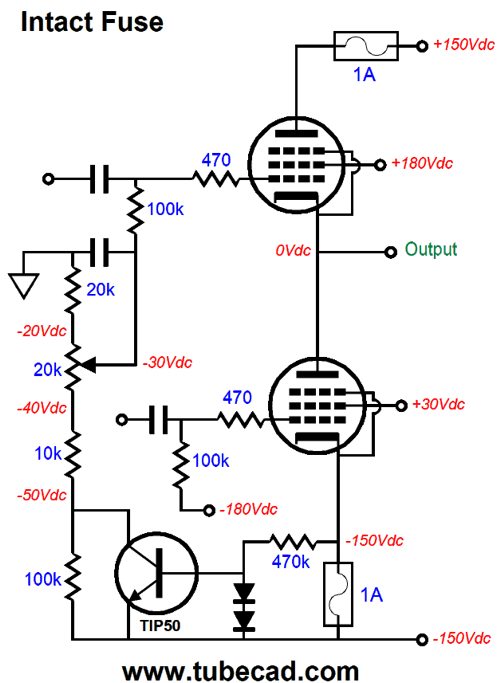
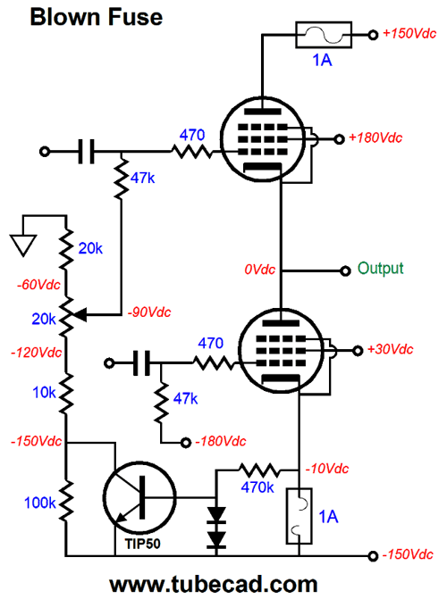
A Safer OTL Fuse Setup As shown, the fuse is intact and the TIP50 NPN transistor is turned off, as its base and emitter are at the same voltage potential, -150Vdc. If the negative power-supply fuse opens, the bottom output tube's cathode will climb up in voltage, which in turn will turn on the transistor, causing its collector to swing down to almost the negative power-supply rail voltage.
The top output tube's grid now sees a grid-bias far lower in voltage, enough so that the tube ceases to conduct. The two diodes in series are there to protect the transistor from excessive base voltages. Imagine if I were a patent attorney—the US Patent Office would be working overtime. Fortunately, I am not a patent attorney and the $5,000 patent legal fees allows the clerks to go home early on Fridays.
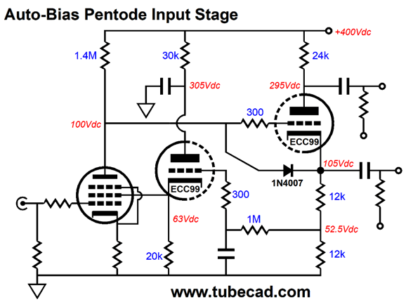
OTL Auto-Bias Pentode Input Stage The PNP transistor monitors the input pentode's plate voltage indirectly through the split-load phase splitter. If the plate voltage is too high, the transistor's base will see too great a negative voltage relative to its base, which will cause the transistor to increase its current conduction, which in turn will increase the input pentode's screen voltage, causing the plate voltage to fall in line with the 100V Zener reference voltage. The transistor type is not marked. The MJE5852 is rated for 400V and offers an 80W power dissipation limit, which means that without a heatsink, it's probably good for at least 2W. The ZTX560 comes in the tiny E-Line-3 package and is rated for 500V; I would glue it to a small heatsink. (Missing from the schematic are a bunch of safety diodes to protect the transistor from excessive base voltages.) For those who shun solid-state devices, the following all-tube circuit should bring a smile. The split-load phase splitter and the cathode follower form a DC negative feedback loop. If the plate voltage is too high, the input pentode's screen voltage rises, prompting an increase the pentode's current flow, which creates a bigger voltage drop across the pentode's plate resistor, which in turn reduces the pentode's plate voltage. Which circuit is better? It depends. If you do not plan on moving and if your wall voltage is constant, then the transistor-based version would work best. If you are selling OTL amplifiers and your customers live all around the world, then the all-tube version is probably best, as it scales nicely with wide variations in B+ voltage.
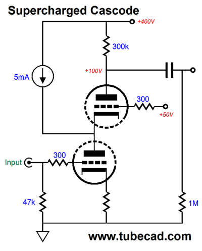
Non-Pentode OTL First Stage
Getting a gain of 100 from a 6DJ8 is fairly easy, but we need far more gain. The workaround is the following topology. The bottom triode conducts 6mA of current, while the top triode conducts only 1mA. The missing 5mA is supplied by the 5mA constant-current source. With some tweaking, we can gains from 700 to 1,000. Here is an all-tube version. The leftmost triode, a 12AT7, functions like a constant-current source, alas its actual output impedance falls short of infinity, coming in at about 1.5M. Its partner 12AT7 triode draws about 1mA. In SPICE simulations, the gain was about 750 or 57.5dB. With a 400k plate load resistance, we would get close to a gain of 1,000 or 60dB. Note the auto-bias feature employed by the DC negative feedback delivered to the cascode's top triode's grid. I am inclined to think that this circuit would deliver less distortion, lower noise, and wider bandwidth than the pentode version. One hidden problem is that we need to use separate heater power supplies to power the 12AT7's heaters, as it should be referenced to 110Vdc, while the 6DJ8 heater power supply should be referenced to 50Vdc. One last tweak is needed, however.
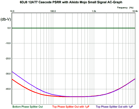
As wall voltage drift and tubes age, the PSRR null may also drift off target. The added potentiometer allows fine tuning the power-supply noise null at the output. No DC current flows through the potentiometer's scraper, so we are safe. The 10µF capacitor may seem to be too large in value, but it isn't. Here is the SPICE-generated graph that shows the PSRR versus frequency with a 1µF and 10µF capacitor.
Note that 100Hz and 120Hz are key, as that is the fundamental ripple frequency, depending on whether your wall voltage frequency is 50Hz or 60Hz. Ideally, we would want to flat portion to center at these frequencies. By the way, our goal was zero PSRR for the inverting phase splitter's output that goes to the bottom output tube; and as much PSRR as we can get from the non-inverting output that goes to the top output tube. Here is the transient graph that shows how much of the 1Vpk of signal riding on the B+ voltage leaks out the two phase splitter outputs.
Just what we want, as the negative feedback can clean up the small mess left behind.
Music Recommendation: Indra Rios-Moore
If you haven't tried one of my recommendations, do give her a listen. This New Years Eve, I plan on doing so. //JRB
User Guides for GlassWare Software
For those of you who still have old computers running Windows XP (32-bit) or any other Windows 32-bit OS, I have setup the download availability of my old old standards: Tube CAD, SE Amp CAD, and Audio Gadgets. The downloads are at the GlassWare-Yahoo store and the price is only $9.95 for each program. http://glass-ware.stores.yahoo.net/adsoffromgla.html So many have asked that I had to do it. WARNING: THESE THREE PROGRAMS WILL NOT RUN UNDER VISTA 64-Bit or WINDOWS 7 & 8 or any other 64-bit OS. I do plan on remaking all of these programs into 64-bit versions, but it will be a huge ordeal, as programming requires vast chunks of noise-free time, something very rare with children running about. Ideally, I would love to come out with versions that run on iPads and Android-OS tablets.
//JRB
|
|
I know that some readers wish to avoid Patreon, so here is a PayPal button instead. Thanks. John Broskie Special Thanks to Francis Oconnor
John Gives
Special Thanks to the Special 83
I am truly stunned and appreciative of their support. In addition I want to thank the following patrons:
All of your support makes a big difference. I would love to arrive at the point where creating my posts was my top priority of the day, not something that I have to steal time from other obligations to do. The more support I get, the higher up these posts move up in deserving attention. If you have been reading my posts, you know that my lifetime goal is reaching post number one thousand. I have 513 more to go. My second goal was to gather 1,000 patrons. Well, that no longer seems possible to me, so I will shoot for a mighty 100 instead. Thus, I have 17 patrons to go. Help me get there.
Only $12.95 TCJ My-Stock DB
Version 2 Improvements *User definable Download for www.glass-ware.com |
||


| www.tubecad.com Copyright © 1999-2019 GlassWare All Rights Reserved |