| John Broskie's Guide to Tube Circuit Analysis & Design |
|
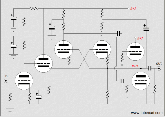
03 Dec 2002 Regrouping (continued from 11/28) I used every trick I could think of and I even tried a cross-coupled driver stage topology; alas, the distortion remained too high for my taste and I didn’t want to up the number of input and driver tubes.
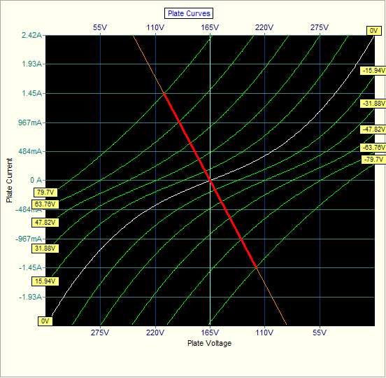
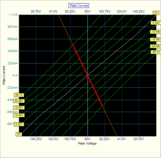
Solving the first “problem,” too much output wattage, by reducing the number of output tubes will only make the second problem worse, if the same 32-ohm load is specified. On the other hand, solving the second problem, too much distortion, by decreasing the B+ voltage and upping the idle current will both reduce the output wattage and lower the distortion. The combined plate curves makes the point:
Notice how much more linear the bottom set of curves is. By increasing the idle current (80mA vs 40mA) we have moved the amplifier’s output stage further into class-A mode. The amplifier is still a class-AB amplifier, but a much-more-heavily-biased-into-class-A amplifier. Additionally, the output stage becomes safer, as the 6AS7 is known to arc at high voltages, halving the B+ voltage probably quarters the likelihood of a mishap. All of this sounds great, but what did we lose in the bargain? The potential output wattage has been reduced to a sixth of its old value (5 watts, instead of 30 watts) and the input and driver stages lose potential B+ voltage, as their power supply is parasitically derived from the output stage’s power supply. The danger with losing input and driver stage B+ voltage lies in potentially adding distortion from the frontend to the backend. In other words, we might have linearized the output stage at the expense of losing linearity in the input and driver stages because of the new lower voltages. But we may still come out ahead, as the new configuration requires only a third of the driver swing as before, so the effective feedback ratio of the driver stage has also been increased. How could we cheat the system and retain the high output wattage and reduce the distortion? The only answer would be to do what the solid-state boys do: pack as much gain into the amplifier as we can, so that more feedback can be applied. This would require more input and driver tubes. it would also require a great more caution and tweaking than any computer amplifier deserves. A little more testing and the values will finally arrive. //JRB |
Tube CAD does the hard math for you. Windows 95/98/Me/NT/2000/XP |
|||
| www.tubecad.com Copyright © 1999-2004 GlassWare All Rights Reserved |


