| John Broskie's Guide to Tube Circuit Analysis & Design |
04 June 2006 Buffers and more buffers Let’s began with some taxonomy. Buffers belong in a subset of amplifiers, in general. In addition, power buffers can be thought of as belonging to a subset of power amplifiers, in specific. (Isn’t taxonomy fun?) The uniting features for all buffers are unity gain and a low impedance output (and, we would hope, low distortion). When we look for commercially made buffers, however, we see that a third feature has been wedged into the feature list—namely, wide bandwidth. Yet for our ear-restricted purposes, bandwidth to 100 kHz is more than enough. (In fact, many great sounding tube amplifiers have a power bandwidth that only extends up to 40 kHz.) A common, but not universal, additional feature that many buffers share is that they are feedback free…well, at least, global feedback loop free. (Since the buffer is often used to replace the power output stage of an amplifier—say a low-noise amplifier that cannot on its own drive low impedance loads—feedback-free allows more latitude in wrapping one global feedback loop around both the voltage amplifier and the power buffer.) 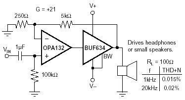
For our purposes, namely, using a solid-state power buffer after a vacuum tube voltage amplifier, low distortion is primary; with low-output impedance and freedom from feedback coming second and third. However, a low distortion buffer comes at a price: high idle current. Ideally, our buffers should only be run under class-A operation. Push-pull class-A output stages are naturally clean, as sharp on-off transitions are excluded and the two output devices’ transfer curves combine in single flatter curve; additionally, class-A operation prevents the problems of switching distortion, gm doubling, and tweaky bias adjustments. Class-A operation, however, is far from efficient. In spite of what the glossy ads say, class-A is brutal, requiring a heavy current draw and lots of heat, requiring massive heatsinks and heavy transformers. This isn’t news and everyone knows this, except for those who work in the high-end audio industry. For example, just the other week, I received a catalog from Audio Advisor. First of all, I like Audio Advisor; in fact, I buy stuff from them and will continue to do so. Now comes the “but.” But someone who understands amplifier modes of operation, say an appliance repairman or a high-school science teacher (or anyone who does not regularly attend Stereophile shows), should point out that the Vincent SV236 integrated amplifier, shown on page 53, contrary to what is stated, most likely is not a class-A one. Well, at least not its output stage. Yet, the amplifier’s description touts:
My first thought was, Since the unit held three 12AX7s and everybody knows tube gear is from Venus and science and math are from Mars, all the normal rules of electrical engineering could be dismissed: if you think it is a 100W class-A, it is. My second thought was, Wait a minute; isn’t Vincent a German company? Aren’t the Germans known for being exact? Even when they are wrong, they are wrong in an exacting way. So, maybe this 17-inch wide, 6-inch tall chassis does indeed hold two 100-watt class-A amplifiers and three 12AX7s. What if six muffin fans are mounted on the bottom or what if Peltier cooling devices were liberally used and connected to large and massive heat-sinks inside with a powerful fan blowing through it? What if no power transformer was used, relying instead on a rectified wall voltage, like the old Futterman OTL amplifiers? Well, I had almost convinced myself that it was possible to cram all those 200 class-A watts into a conventional looking integrated amplifier’s chassis. I then visited Audio Advisor’s website to see if I could copy the text I quoted above (yes, I am that lazy). Well, guess what? The Vincent Audio SV-236 hybrid amplifier does sport a class-A output stage, for the first ten watts, thereafter it runs in class-B. Here is what their website says:
I am not sure why “Class A” was wrapped in quotations; usually, gratuitous quotation marks means “not really,” but then so was “Class-AB.” So which is it? Well, it’s both, as are all class-AB power amplifiers. In other words, the Vincent Audio SV-236 runs a heavy idle current for a transistor push-pull amplifier, 0.8A. Most solid-state push-pull amplifiers run only 50 to 100mA through the output stage at idle, which translates into 40mW to 160mW of class-A output into an 8-ohm load. By the way, tube amplifiers routinely run in a rich class-AB. For example, the Dynaco ST-70 ran each EL34 at 50mA, which translates into 5.375W into an 8-ohm load, after being stepped up by the output transformer. (A tube output transformer steps down voltage and steps up current.) Now, 35W/5.375W equals 15%, whereas 100W/10W equals 10%. So, should the ST-70 have been advertised as being a class-A amplifier? No, no more than a drink containing only 10% real juice should be advertised as being “100% real juice.” The key point here is that all class-AB amplifiers run in class-A for a small portion of their output. A true, pure class-A amplifier runs under class-A for the whole of its output. One thing that I should stress is that I have nothing against the Vincent amplifier. In fact, I would love to listen to it over a weekend. Furthermore, I believe that they might be on the right track, as 90% of music resides in those first 10 watts. I expect that there are two bumps in the transfer function, above ten watts going positive and going negative, as one set of output devices cuts off and the other left carrying the entire load. This can go under the heading of gm-doubling distortion. So, wouldn’t two bumps be worse than one glitch at the zero point? I doubt it. 10 watts is a lot of power; the loudspeakers are probably adding 10% at this power level, which will help mask the distortion. Consider which would trouble you more: one sore on the roof of your mouth, at the top near your front teeth, within your tongue’s easy reach; or two, far in the back behind your molars? Getting back to non-advertising power-buffer design, ideally we want to run the buffer’s output stage in strict class-A, but then we must be willing to accept the consequences, such as huge heat-sinks and a massive power supply. I have said that audio lives off the crumbs that fall off the technology table. Well, one hot tech toy today is the computer. High-school students are hot-rodding their computers and huge accessory industry sells aftermarket additions for the stock PC. Cooling is a big problem for the new powerful CPUs and video cards. (In the near future, I can envisage two outside heat exchangers, one for cooling the house and one to cool the home computer.) Many computer enthusiasts have turned to water cooling as the solution. For a little more than one hundred dollars, we can buy a radiator and water pipe cooling system. What if we used such a cooling rig to cool our solid-state output stage, would we be able to make a smaller class-A buffer? BUF634 The easy way out is to use prepackaged silicon, for example IC power amplifiers and unity-gain buffers, as these in these small and tidy packages all difficult decisions have been made for us; we need only hook up the wires. Of course, their main liability is that all the choices have been made for us and there is little that we can do to alter the device. Ken, a reader from Australia, wrote asking about the suitability of using the Bur-Brown BUF634 with a 6GM8-based Aikido amplifier that used a 24-volt power supply. The buffer and Aikido amplifier would run of the same low-voltage power supply (+24V). If the BUF634s were not so hard to get in the TO-220 package, I think that this would make a wonderfully easy way to build a great little headphone amplifier. This IC boasts some excellent specifications (slew-rate of 2000V/µS, for example) and it just might sound good as well.
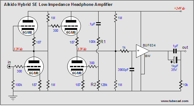
I added the 1k resistor and 3900pF to limit the high-frequency bandwidth to 40kHz; feel free to experiment. This circuit looks truly cool to me; I would love to hear it in person. The IC can withstand 36 volts across it, so it might be fun to experiment with 36V as the B+ voltage, but I am sure it will sound great with just the 24 volts, or even only 12.6V. Careful wiring practice is critical with this device, as it is a super-wide bandwidth design, so a low-inductance layout is crucial as are power supply bypass capacitors at the IC’s power supply connections. As a National Semiconductor datasheet puts it:
If you look at the idealized schematic of the device, you’ll that there isn’t much there, which means that you could build a discrete version with only 8 transistors and a handful of resistors and a few diodes. But I must admit that using the IC is much easier, although I am sure that the discrete version would hold a real, but small, sonic advantage. 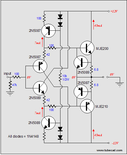
Wedding this buffer to the Aikido is easy enough: 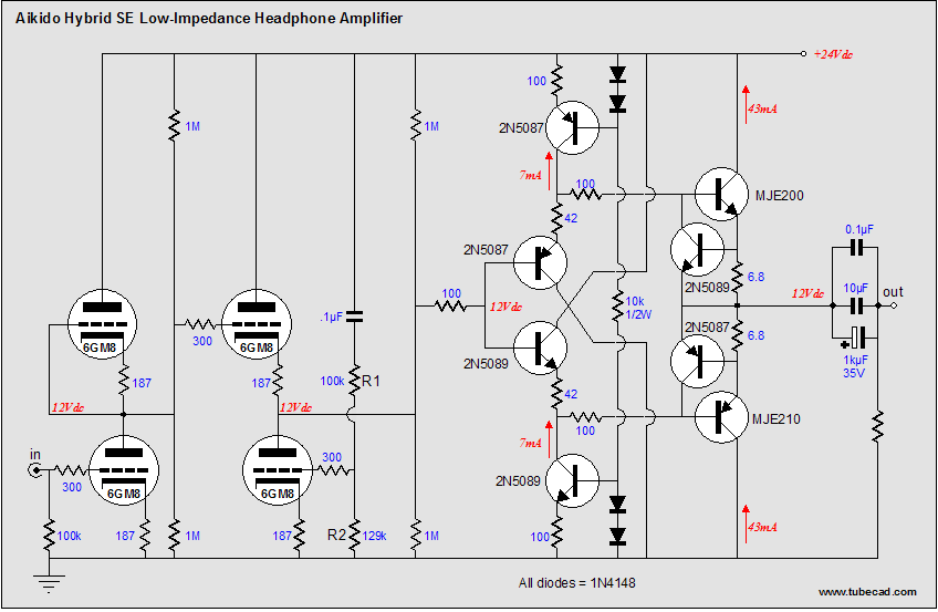
By the way, with different trnasistors (high-voltage transistors), the above circuit could be modified to use a B+ of 200V or, even, 300V.
Power buffers for loudspeakers If you do plan on using the LM12, then I recommend using it in an inverting fashion. There’s an old saying analog electronics, “Whenever possible, invert.” Using the inverting configuration will yield two benefits: greater high-frequency stability and less distortion. 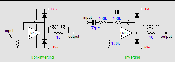
First of all, the non-inverting configuration seems much less complicated. For example, the input coupling capacitor might be seen as a liability in the inverting configuration on the right, but the Aikido amplifier requires a coupling capacitor on its output, so either configuration will require a coupling capacitor; thus, it’s a wash. What cannot be seen, however, is what goes on inside the power IC amplifier. By using the inverting scheme, the high-frequency feedback stability is enhanced by the constantly falling high-frequency output, which the capacitor in parallel with the feedback resistor provides. In either configuration, the LM12’s high-frequency bandwidth will fall off, but with the inverting configuration, the feedback ratio will remain constant at high frequencies, as the shunting capacitor will force the amplifier output down at some high frequency below the IC’s natural transition frequency, creating a safety cushion of constant feedback. The lower distortion is the result of the LM12’s input not having to move up and down with the input signal, which could be as big as 60-volts peak-to-peak. In contrast, the inverting configuration keeps both inputs at ground level, with minuscule input voltage swings at both inputs. So, while the LM12 is a good amplifier, it would be desirable to have more options.
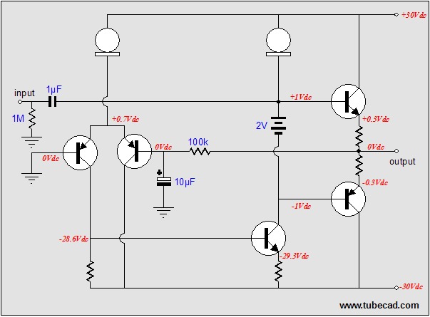
Crazy but good idea In other words, why not buy a decent solid-state push-pull amplifier on eBay or at a garage sale and convert it into a unity-gain power buffer. No, we do not strip away the input stage, we just modify it so that it only controls the DC offset at the output. Huh? Without a DC feedback loop and a lot of DC gain, most solid-state power amplifier outputs would just slam to one power supply rail, as any slight discrepancy in idle current in the driver (VAS) portion will throw the output to rail that holds the bigger current hog. On the other hand, the feedback loop provides 100% DC feedback, which the input stage uses to adjust the driver stage so that the output centers at 0Vdc. This is certainly a good feature to keep. Below is an extraordinarily boring solid-state push-pull amplifier. 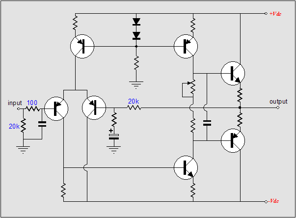
This topology looks about 30 years old, but its simplicity can be an asset, as it would be easy to convert it into the following circuit. 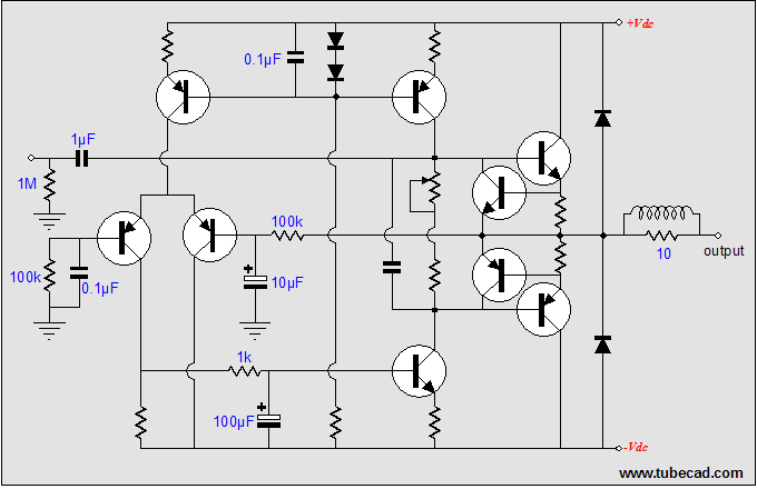
Above, we see the fleshed out amplifier converted into an AC-feedback power buffer. The existing input and driver stages have been shunted out of AC amplification, becoming no more than a discrete DC servo amplifier that maintains a low DC of at the output. Note how all of the AC output signal is shunted to ground via the 10µF capacitor and the error correction signal from the input stage is shunted to ground via the 100µF capacitor. What we are left with is two constant-current sources loading the voltage reference in the center of the driver stage and this voltage reference connects via a coupling capacitor to the outside world. I know that many were just getting it with the first schematic of the simple solid-state amplifier, but this modified version has turned off the lights for them. So I have shown below an idealized version of this modified circuit. Maybe it will turn the lights up a bit.
Next time 
//JRB
|
|
||||||||||||||||||||||||||||||||||||


| www.tubecad.com Copyright © 1999-2006 GlassWare All Rights Reserved |