| John Broskie's Guide to Tube Circuit Analysis & Design |
11 March 2010
Balance
Balanced audio confuses many—and would confuse many more, if they knew it existed. For those acquainted with balanced audio, what immediately pops into mind are XLR connectors and professional audio equipment. Then soon follows the varied rumors, such as "Although balanced audio is used extensively in making LPs and CDs, balanced audio never sounds good in home systems" and "Balanced systems are the only possible way to get low-noise, high-quality sound and the cheapest, most-humble balanced cable sounds vastly better than the best, most-expensive unbalanced cable." I have heard both of these rumors and many others in between and a few crazy ones, such as "Balanced systems will strip away even-order distortion from a music signal, leaving only odd-order harmonics in place." Indeed, balanced audio confuses many.
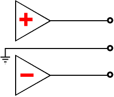
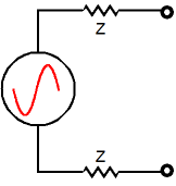
If asked to define a balanced signal, the most popular answer is three wires and two phases. Yes, a balanced signal consists of two* anti-phase and symmetrical signals, thus seemingly implying the necessity of three wires, plus, minus, and ground, but many balanced signal sources only use two wires, such as all telephone systems (excluding optical and radio transmission), microphones, temperature sensors, photo cells, and even phono cartridges. In other words, three wires are not essential.
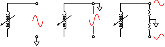
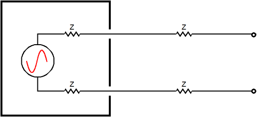
What is essential is that the two signal-carrying conductors be of the same type and that each present an equal impedance relative to the receiving circuit’s voltage/signal reference (ground). The key feature here is the two wires presenting equal impedance, not that they be in anti-phase. In other words, getting two phases is something of a freebie in a balanced setup. (The name "balanced" was maybe unfortunate, as would have been "symmetric"; while "stabilized" or "equalized" might have been more fortunate.) For example, consider a phono cartridge's coil; if one end is grounded, then only one phase is present; no balanced signal. But if the coil is shunted by two equal resistors in series and if junction between the two resistors are attached to ground, cartridge's output signal now offers two phases.
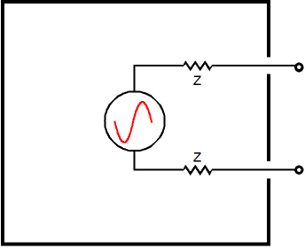
Since the cartridge's coil is not hardwired to a reference/ground, we can decide where the reference point will be attached. (Even if phono cartridges had always come with center-tapped coils, we could choose to ignore the center-tap and treat the coil as a free, non-referenced signal source.) Sure, this makes sense with a phono cartridge's coil, as it is just a length of coiled wire, but what about an actual active electronic audio signal source? Surely here the signal reference is hardwired defined and not free-floating. Sometimes it is, but sometimes it's not. Imagine an unambiguously unbalanced signal source, such as an old portable mono cassette tape player housed in a big metal box and its two output signal wires exiting the box. (Since the tape player uses batteries, no connection needs to be made to the house wall voltage.)
Do we now have a balanced or unbalanced signal source? The answer can be that it is balanced, as long as we do not "ground" the tape player's own internal ground directly to the house ground or to our line-stage amplifier's ground. This signal source can be—and maybe must be—voltage referenced in some fashion to our line-stage amplifier.
If we wish to treat this signal source as a balanced signal, then we can attach the two-equal-valued-resistor voltage dividers across the two leads, thereby referencing the tape player's output at the midpoint of its output signal and thereby creating two signal phases (and effectively halving the signal amplitude). In other words, the tape player's internal ground becomes a signal output, just as much as its conventional signal output. As far as our line-stage amplifier is concerned, both signal phases are equal in amplitude and output impedance and, thus, are interchangeable. This allows easy phase reversals and eliminates the need for a phase splitter. How can that be? Since one of the two wires leaving the box attaches directly to the tape player's ground, the output impedance of this wire must be zero. Ground, unfortunately, is something of a metaphysical notion, not an actual physical entity. In an airplane or a satellite or a ship or the iPod in your pocket, where is ground? Almost ten years ago I wrote the following:
The tape player's ground exists only within the tape player, nowhere else. Give an electrical engineer the black box with two wires protruding, but do not tell him what is inside. He measures all that he can measure but he never discovers a ground. If the tape player is turned off, he would conclude that the box held a single resistor; if the tape player is turned on but not playing a cassette, he would deduce that the box held a complex RC network that used noisy resistors; and if audio signal left the box via the two wires, he could only speculate on its actual source. Maybe the box concealed a radio or MP3 player or a phonograph or… But he could never make a distinction between the two wires, never differentiate one wire as being the hot and the other as the ground. How could he? The phase of the signal would not help, as the tape player's circuitry might invert the phase and who knows what the phase relationship was on the tape itself. One wire cannot be measured in isolation, so one wire cannot exhibit zero ohms of impedance, thus betraying its designated "ground" status. As far as the VOM can tell, both wires present the same impedance, much a single resistor would. (Imagine if someone told you that each resistor held a ground lead and an output lead, that the ground lead offered zero resistance and output lead presented all of the resistor's resistance. Just because such a fellow could write for an audio magazine or design high-end audio gear or be awarded a patent, does not, sadly, preclude his also being harebrained.)
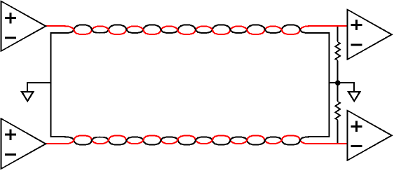
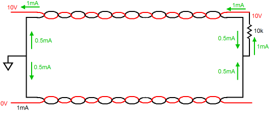
So far, we have assumed that the two wires are identical in construction and they should be. The longer the wires and the nosier the electronic environment, the more important this becomes. Equal impedance presented by both outputs and its cabling are essential to realizing a balanced-signal transmission's famed noise immunity, as the equal impedances ensure equally noise-contaminated signal conductors. Yes, equally polluted. But having equally noise-contaminated signal conductors is a feature. Once the signal's source's load is attached, the common-mode noise drops out of the mix, leaving only the audio signal present. This magical feat is labeled common-mode rejection ratio (CMRR) and is measured in dBs. It is the ratio between how much common-mode signal is attenuated relative to the differential signal. For example, if the common-mode signal is reduced to one tenth of its amplitude at the receiving load, then the CMRR is -20dB (20 x Log[Vout/Vin] gives the conversion to decibels). The signal-receiving device can be a transformer's primary or a differential amplifier's input or a headphone/loudspeaker coil—all of which will ignore any signal common to both signal conductors. In theory, all common-mode signals can be ignored by the receiving device; reality, as usual, disappoints. Nonetheless, even a paltry 20dB CMRR is welcome and it constitutes a huge improvement over the alternative.
Unbalanced "But I don't like push-pull amplifiers," I can hear many of you muttering. Well, you do not have to use push-pull amplifiers with balanced signal transfer. For example, the tape player in the box could run entirely single-ended amplifiers throughout and still present a balanced signal to the world; and push-pull output stages (think OpAmps) routinely feed unbalanced signal outputs, such as RCA jacks. The key issue here is how do we transfer signal from one device to another cleanly, not how do we process the received signal. Others are thinking, "While I concede that balanced signals are essential to live performances and recording studios, because of the miles of cabling used and the dirty electrical environment within stage and studio; in my house, I don't need the added complexity of balanced signals." The truth is that our houses are not as electrically clean as you might imagine and the complexity already exists in the form of ground-loops and incoherent wiring layouts. Balanced signal can actually undo much of this hidden complexity. For example, let's say you have just hooked your unbalanced $10k CD player to your unbalanced line-stage amplifier with some equally impressive $10k interconnect made from pure einsteinium (and it only sounds half as good after 276 days) and designed to conform to the most exacting physical geometry, which will ensure its faultless signal transfer. (As the manufacturer states in his ads: It's better to use this interconnect with a $100 stereo than to use $100 cable with a $10,000 stereo.) Now play a track with audio signal in only one channel. Will the entire signal remain confined to one interconnect?
No. Instead since the two cables make a common ground connection in the CD player and line-stage amplifier, one channel's hot and both channels ground returns will see the signal flow, as the two ground returns are effectively in parallel.
Here's another example. You own a lot of gear, so you use up all wall outlets in your listening room. No big deal right? Wrong. If our houses were wired with star ground and star hot and star neutral in mind, wherein each socket got its own discrete and isolated set of three wires back to the house control panel, plugging into different sockets would make no difference. Instead, our house outlets are daisy chained together, so each load sees a slightly different AC and ground voltage, due to the voltage drops along the wires path. Worse still, some gear is miswired at the factory, so the neutral and ground are joined within the piece of equipment, which means that ground wire see real current flow, maybe several amperes! And of course, all the equipment holds a grounded chassis, many of which attach directly to the house ground. Thus, your fancy $10k interconnect is also in parallel with house ground wire, which is neither made from pure einsteinium nor noise free. It's a mess.
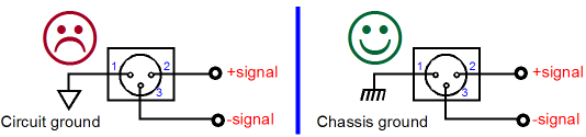
To be honest, I must also admit that many balanced setups are also a mess, because of the dreaded Pin-1 problem, wherein the shield pin on the XLR connector is directly soldered to circuit's ground. (see "Hum & Buzz in Unbalanced Interconnect Syestems" by Bill Whitlock and "Sound System Interconnection" by Rane Corporation for more information.)
On the other hand, let's say that you love huge, push-pull, tube power amplifiers. Designing such a beast is much easier when you start with a balanced input signal, as it bypasses the need for a phase splitter.
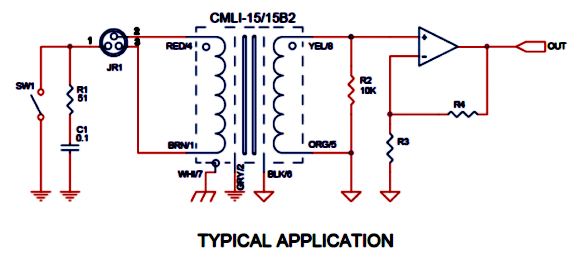
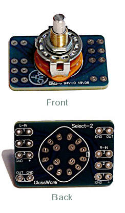
The transformer's primary leads attach to one of my Select-2 signal selector switch PCBs and the secondary to my 20k Elma-based three-switch attenuator. (I could place a 60k resistor in parallel with the attenuator to bring the load impedance down to 15k, but I haven't felt the need to experiment.)
The interesting design feature employed here is the absence of ground connections. Most line-stage amplifiers hold fistfuls of RCA jacks, all of which are grounded either at the chassis or at a common ground bus wire; and most select only different hot inputs, not different ground connections.
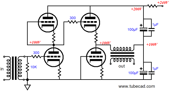
In my Aikido line-stage amplifier, all the input RCA jacks are isolated from the chassis and each of the jack's ground connections is treated individually, as if the jacks attached to balanced signal sources. Thus, a twisted pair of wires leaves each jack and attaches to the selector PCB assembly, whose switch selects right and left channel hots and grounds, never combining the grounds. So as far as the input transformer is concerned, the input signal it sees comes from a balanced signal source. The output signal leaving the transformer's secondary can be treated as either a balanced or unbalanced signal, although the secondary does not offer a center-tap. Because my Aikido line-stage amplifier delivers an unbalanced output, I choose to treat the signal as being unbalanced. But I could have doubled up on the number of tubes and used the input signal as a balanced source. Or I could add an additional transformer.
I have covered this circuit a few times before, so I will not go into all the details. But I will add that the output transformer will never see a DC current on its primary, so nickel transformers could be used and the two electrolytic capacitors could be replaced by two large film capacitors, as each sees only half of the B+ voltage, so 250V film capacitors could safely be used. Note how each channel has three signal sources to select from, including an XLR jack. My Cambridge Audio DacMagic offers balanced output along with unbalanced, so the XLR jack gets used. In fact, an additional advantage to using the DAC's balanced output, besides greater gain and less noise, is that DAC's balanced output comes earlier in the DAC output circuitry, and bypasses one additional OpAmp. Also note how all the grounds are left floating. This works fine in my system (I cannot hear any hum with my ear pressed tight against the woofer, although I can hear the power transformers softly hum away.) In other systems, RFI might infect the line-stage amplifier. The workaround is to attach a small disk capacitor to each RCA jack and each XLR pin-1 to the chassis, close to where the jack fits into the chassis. (If unshielded interconnect is used, extra disk capacitors will be needed across hot pin and chassis.) How does this input transformer sound? I like it a great deal. It's dead quiet and does not seem bandwidth limited. One interesting side effect is that sonic image has become much larger now, so much so that I should move my loudspeakers closer together. At first, I concluded that the transformer introduced odd phase anomalies that tricked the ear to hear wider soundstage. My most recent conclusion is that the input transformer works to truly separate left and right channels, thereby preserving more vital sonic clues for the ear, resulting in the wider image. (The last time I used an input transformer was twenty years ago when I got horrendous hum from a cable-TV connection and which only an input isolation transformer could cure; that transformer, however, was not nearly as well-made as the CineMag. Twenty years ago is also the last time I have had cable TV; there is very little tele in my vision.) Next Time
//JRB |
High-quality, double-sided, extra thick, 2-oz traces, plated-through holes, dual sets of resistor pads and pads for two coupling capacitors. Stereo and mono, octal and 9-pin printed circuit boards available.  Aikido PCBs for as little as $24 http://glass-ware.stores.yahoo.net/
|
|||


| www.tubecad.com Copyright © 1999-2010 GlassWare All Rights Reserved |