| John Broskie's Guide to Tube Circuit Analysis & Design |
29 January 2020 Post Number 490
Sorry for the Lag For those waiting for the release of the SE HPA PCBs, I have yet to finnish the writing the user guide. My last travail was a project that I botched. I wanted to show how easy it was to assemble a unity-gain line-stage amplifier and phono preamp in a 17-inch wide enclosure.
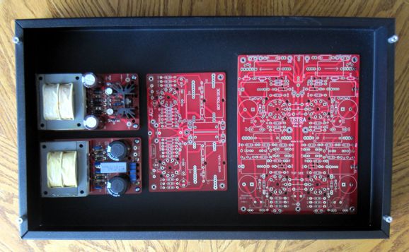
The first step was to see if the four PCBs would fit. They did. The next step was to see if the tubes (12AT7 and 12AU7) would fit within the 3-inch tall enclosure when mounted on ceramic sockets and the PCB stood atop 1/2-inch standoffs. They didn't. They came close, but were too tall. I then attached 1/4-inch standoffs between the chassis and the top panel; I then tried again.
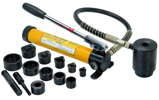
With the standoffs in place, the tubes fit and the hot air could escape from around the perimeter. If only I had stuck to this plan. The problem is that I like seeing tubes protrude from the chassis and I own a hydraulic hole punch, which I bought for about $100 from Harbor Freight. If you own a hammer, you seek nails.
I had build so many tube-based headphone amplifiers recently that I assumed that I could drill and punch an enclosure with my eyes closed. Verily, Pride goeth before destruction, and an haughty spirit before a fall. I very little time, I had drilled al the holes I needed before I could punch larger holes.
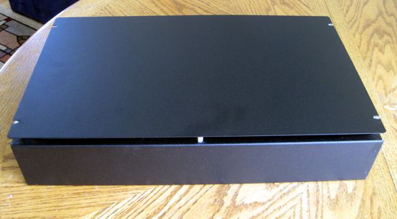
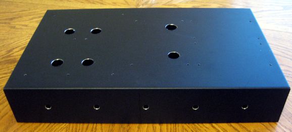
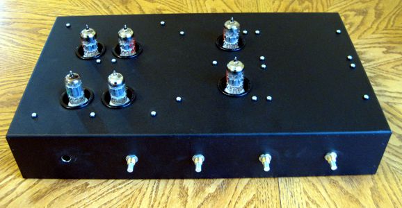
That is the top and front.
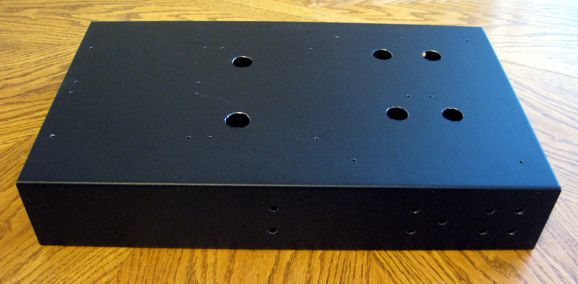
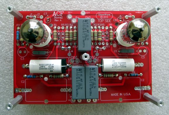
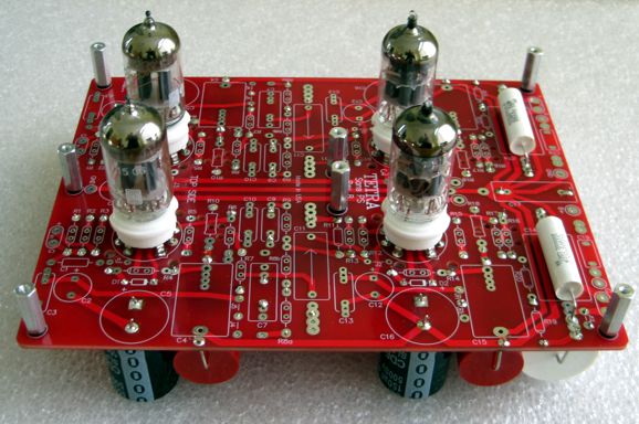
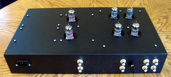
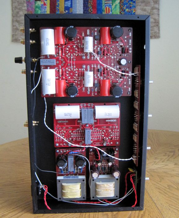
And that is the back view. I assembled the PCBs, so that the tubes could stick through the top. Here is the ACF PCB.
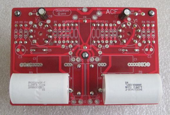
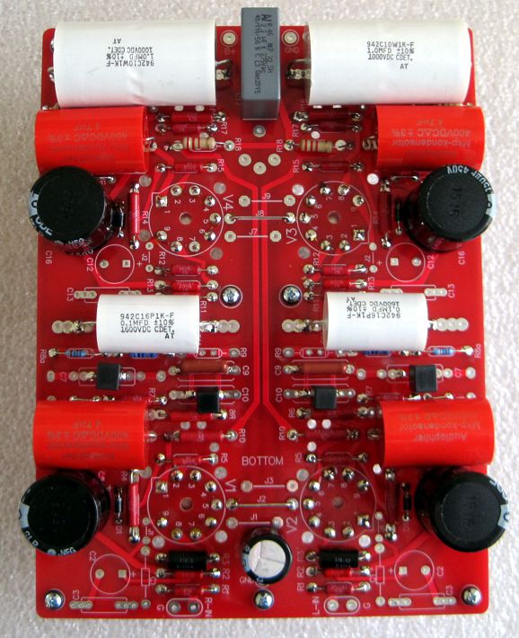
Here is its bottom, where the large CDE 1µF coupling capacitors reside.
The Tetra phono preamp top:
And its bottom:
I had discovered a stash of PRP metal-film resistors that I forgot that I owned. They are red, which explains why they cannot be seen on the red PCB.
Looks good, doesn't it? Here is the rearview.
So, what went so horribly wrong? I didn't discover it until I started wiring it up.
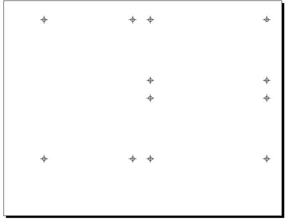
I installed the RCA jacks, A3 stepped attenuator, power switch, and assembled PCBs. Still don't see it? I confused the front for the rear, so the Tetra PCB no longer finds its inputs near the RCA jacks. Dang. Double Dang. Although I would love to blame someone else, such as my wife and kids and dogs, but I have only myself to blame. What makes all of it especially painful is that the enclosure came with a scratch on one face, which I covered with a permanent-ink marker. I intended to make the scratched side the rear where the RCA jacks would go, but I didn't see the scratch. Why Not? I decided to get clever and create paper templates where the ACF and Tr-PS-1 and Tr-PS-2 PCB mounting holes needed to be.
I also made one for the Tetra PCB and the front and rear panel holes. Well, apparently with the paper covering the chassis, I failed to see the scratched side. I will be putting on my thinking cap before I go any further with this project. Quite probably, the best solution would be to create a new chassis.
Tiny OTL? The big problem that OTL power amplifiers face, however, is that loudspeakers usually come in either 4- or 8-ohm impedances, which necessitates using many big OTL output tubes, as all tubes are current limited compared to a transistor or MOSFET. For example, a Futterman-style OTL that used 300B as output tubes would require eight 300Bs to put out 4W into an 8-ohm load. In other words, there are only big OTL amplifiers, no small OTL amplifiers, no equivalent to a 2A3-based flea-power amplifier or a sweet EL84-based push-pull amplifier. On the other hand, if we could readily buy high-impedance loudspeakers, things would be different. (Long ago, they used to make 600-ohm fullrange drivers for use in radios.)
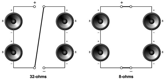
In past posts, I have shown how we could build a 32-ohm loudspeaker that held four 8-ohm drivers. The advantage that the four 8-ohm drivers deliver is that we can rearranged the drivers to create either an 8-ohm or a 32-ohm load. A 32-ohm loudspeaker would make building an OTL amplifier four times easier or, put differently, allow the OTL to use one fourth as many output tubes.
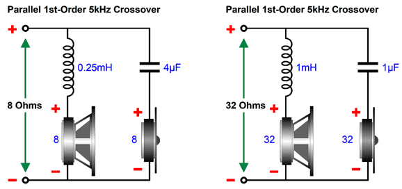
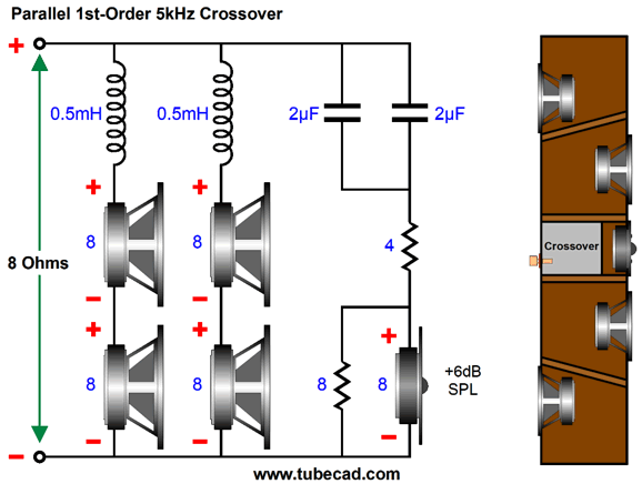
If we use fullrange drivers, our job is pretty much done. Adding tweeters, however, complicates things. Why? Crossovers. Rearranging the crossover parts to work with both load impedances is in itself an interesting puzzle. For example, a simple 1st-order parallel crossover at 5kHz for 8-ohm drivers requires an inductor of 0.25mH and a 4µF capacitor. In contrast, the same crossover for 32 ohms requires 1mH and 1µF. Ideally we want to reuse all the crossover components, rather than have to switch between two separate crossovers. (High-end loudspeaker crossover capacitors and inductors sell for hundreds of dollars, if not more than a thousand dollars.)
One easy way to get to 32 ohms would be to use two 16-ohm woofers and an especially efficient 8-ohm tweeter. (One possible 16-ohm driver is the 4-inch FaitalPRO 4FE35 fullrange.) The famous D'Appolito speaker arrangement of placing a tweeter in between two woofers would be the obvious setup.
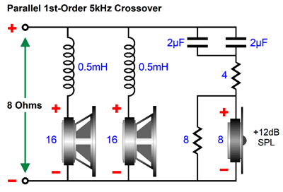
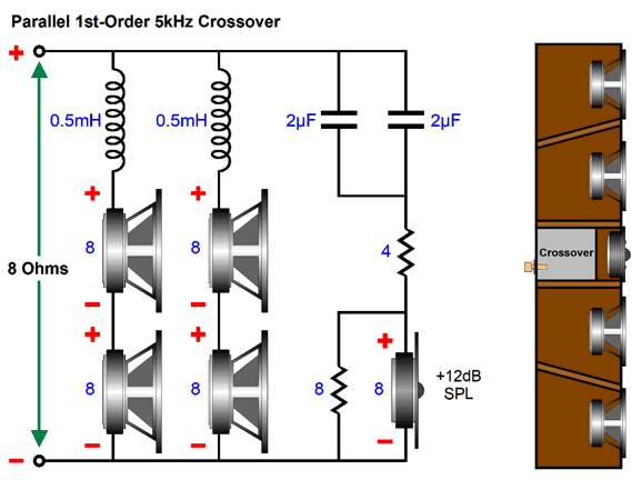
When we desire an 8-ohm loudspeaker, the two 16-ohm woofers are wired in parallel, each getting its own inductor. Let's arbitrarily ascribe an SPL of 80dB with 2.8Vpk of signal to each woofer (the FaitalPRO fullrange is far more efficient). Being in parallel, both woofers would see the entire input signal, but the doubling of radiating surface results in a +6dB increase in SPL, bringing the pair up to 86dB with 2.8Vpk of input signal. To bring the tweeter's output in line with the woofers, a tweeter with an SPL of 92dB would need a resistive-padding network to reduce its output by -6dB.
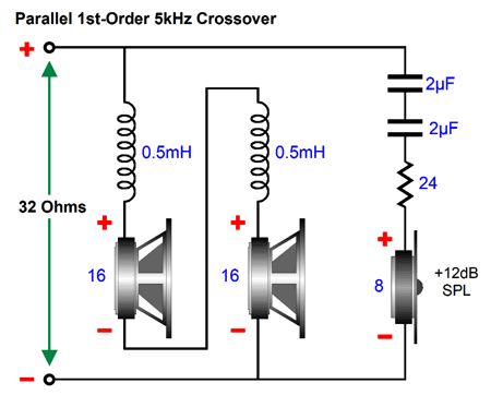
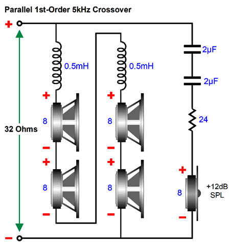
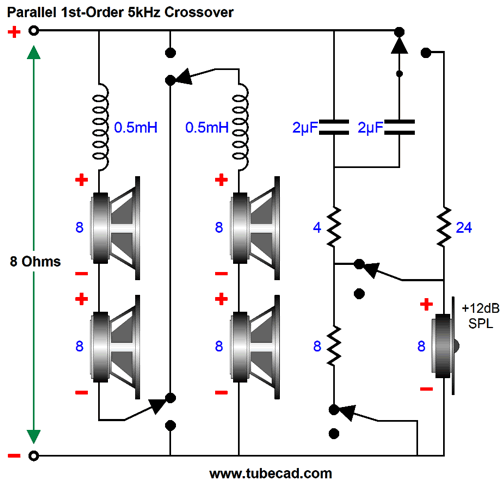
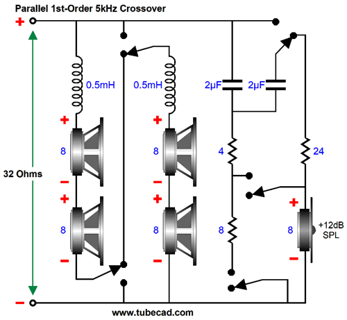
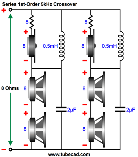
The two 2µF capacitors combine to present 4µF of capacitance, which works with the 8-ohm impedance presented by the padding network and tweeter. On the other hand, when we desire a 32-ohm loudspeaker, the two 16-ohm woofers are wired in series, each still getting its own inductor, with the two inductors effectively combing to 1mH of inductance, the value needed for a 32-ohm load. The tweeter, on the other hand, must be placed in series with a 24-ohm resistor to bring its load impedance up to 32 ohms and reduce its SPL by -12dB. The two 2 µF capacitors are placed in series, which halves their capacitance, resulting in a 1µF capacitor. The same 2.8Vpk of input signal must now be split by the two woofers, which incurs a drop in SPL of -6dB, but as we have twice the radiating surface, we gain 6DB, so the combined SPL would still be 80dB with 2.8Vpk of input signal . The 92dB tweeter only sees one fourth of the input signal, so its output reduces by 12dB, resulting in an SPL of 80dB with the 2.8Vpk input signal. In short, we have reused the crossover capacitor and inductors in both the 8-ohm and 32-ohm version. The only problem with 16-ohm drivers is that our selection is limited, woefully limited. For example, parts-express.com lists only 22 fullrange drivers with 16-ohm impedances, but 284 fullrange drivers with 8-ohm. This brings us back to four 8-ohm drivers. By the way, an unvoiced assumption of mine has been that small, fullrange drivers would be used, not heavy 15-inch woofers. As the goal was a small OTL power amplifier, the loudspeaker should also be small. Think computer loudspeaker or a system for a bedroom or a small apartment. One 5-inch woofer can sound good, but four can sound amazing. As a teenager, I loved the sound from electrostatic and horn loudspeakers, finding their articulation and dynamics unsurpassed. In contrast, the turgid sound emanating from 12-inch and 15-inch woofers insulted my ears. I built many loudspeakers using 5-inch woofers from Peerless and Philips. One of my happiest efforts was a tall but narrow dipole that held four 5-inch woofers and one 5-inch fullrange, with a small, square Peerless tweeter on the back that crossed over at 8kHz. (The rear-firing tweeter not only balanced the front and rear frequency response, it worked as a Zobel network of sorts that undid the 5-inch driver's own inductance.) This loudspeaker was a variation on the previous dipole that held four Philips 5-inch fullrange drivers and one back-firing Peerless tweeter. The first version sounded amazing, but I thought I could improve the mid-bass with the four Peerless 5-inch woofers, as their free-air resonance was far lower. The crossover frequency between fullrange and woofers was 500Hz, with either a two-8-inch subwoofer or single Klipschorn bass horn to fill in the deep bass below 160Hz. The imaging on both designs was excellent and plucked string instruments sounded real. If we place all four woofers on the front of speaker enclosure in the 8-ohm configuration, the SPL of the 8-ohm version will be 6dB higher than the specified SPL of a single woofer, as each woofer will see 50% of the input signal, reducing each woofer's SPL by -6dB. But as we have four times the radiating surface, the SPL goes up by 12dB, resulting a net gain of 6dB; thus, four 80dB woofers would yield 86dB of SPL. Once again, the 92dB tweeter requires a padding network to reduce its output by -6dB, bringing its output in line with the woofers. When we desire a 32-ohm loudspeaker, the woofers and the two inductors are strung in series. The tweeter sees a 24-ohm resistor to bring its load impedance up 32 ohms, which will also reduce its input signal to one fourth, resulting in a -12dB reduction in SPL, which will match the woofers, as the series arrangement results in -12dB loss and a +12dB gain in SPL, yielding as giant step sideways and a 0db change in SPL for the woofers.
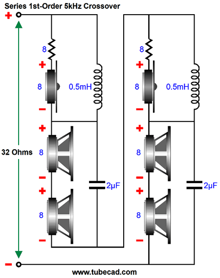
We will need a two-position, five-pole rotary switch to flip the drivers and crossover parts into either 8-ohm or 32-ohm impedances. (I know that 5-pol switches are rare, which is why I would buy a 6-pol rotary switch, which is not rare, and not use one pole.) When we want an 8-ohm impedance, we twist the switch. Returning to the topic of driver placement on the loudspeaker enclosure, If we place two of the woofers on back of the enclosure, the SPL that radiates from the front will drop by 6dB, although the SPL radiated into the room as a totality will remain unchanged. In fact, the dreaded low-frequency diffraction droop will not occur. In addition, since all the woofer fire in phase with each other, the front and rear radiating will cancel the enclosure's back and forth motion, much like a recoil-less rifle that fires two bullets at once, one forward and one rearward. In this situation, the tweeter only needs to offer +6dB more SPL than the woofer, in both the 8- and 32-ohm configurations. A better approach with front and rear firing woofers is to use two tweeters, one on the front and one on the back. The rear-firing tweeter need not be placed in a D'Appolito speaker arrangement. Nonetheless, the reflected sound from the back of the enclosure will match the front in bandwidth and make for a more pleasing sound. In addition, this arrangement greatly simplifies the switching between 8-ohm and 32-ohm impedances.
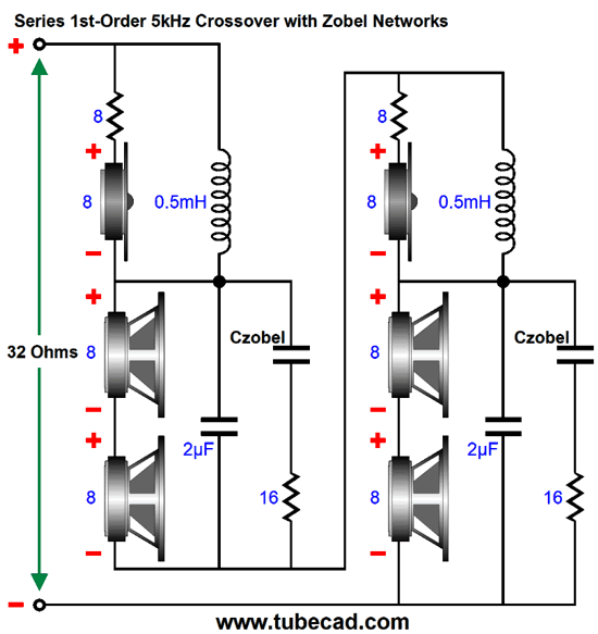
The tweeters need an SPL +6dB higher than the woofers used and each tweeter needs a series 8-ohm resistor to bring their impedance effectively up to 16 ohms. Note that the crossover topology has changed from parallel to series. Converting the loudspeaker to 32 ohms is easy, as all that is required is a two-pole toggle switch.
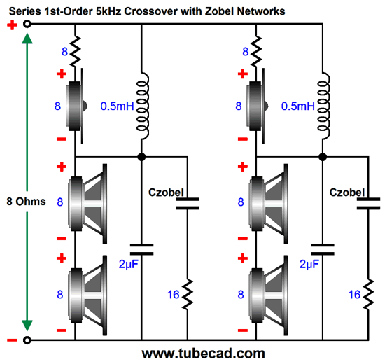
Adding Zobel networks is easy enough.
Note that two woofers share one Zobel network and that a 16-ohm resistor is used rather than the usual 8-ohm. Nothing much changes with the 32-ohm configuration.
Recently, speaker makers have released 32-ohm fullrange drivers. These might prove a godsend in that they can also be all wired in parallel and yield an 8-ohm impedance, or placed in series and yield a 128-ohm load impedance. Now we are talking, as the math reveals. To deliver 16W into a 128-ohm load requires peak voltage swings of 64V and peak current swings of 500mA.
Imagine an OTL amplifier that held four 300B output tubes per channel and put out 16W into the 128-ohm loudspeaker. A 300B can deliver 250mA with a cathode-to-plate voltage of 160V and a grid-to-cathode voltage of 0V. Thus, four could deliver the needed 500mA in push-pull. The tiny 12B4 noval single triode can put out 100mA at 100V of plate voltage. The 6AS7 puts out even more current, as it can deliver 250mA with cathode-to-plate voltage of only 60V. In other words, with a bipolar power supply of +/-130Vdc. We could get 16W into 128-ohms with just two 6AS7 tubes (a total of four triodes). If we doubled the number of 6AS7 tubes and increased the power-supply rail voltages, we would get 1A of peak current swing and 64W of power into 128-ohms. The loudspeaker cable would need shielded terminations, as 128Vac peak appears across the leads. Since we know the peak output voltage swing (128V) and the needed cathode-to-plate voltage (60V), we simply add the two together to get the required bipolar power supply rail voltages, i.e. +/-188Vdc. I would use +/-200V to provide some headroom. Our goal was a small OTL power amplifier, which was next to impossible with 4- and 8-ohm loudspeakers. By raising the loudspeaker impedance fourfold, we can make an OTL one fourth as big.
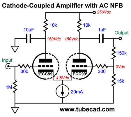
Cathode-Coupled Line Amplifier
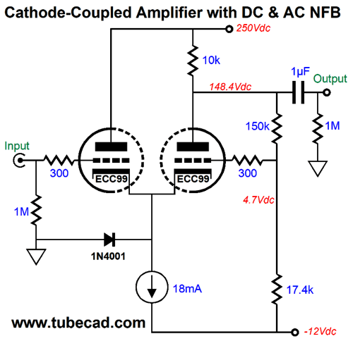
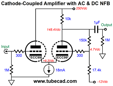
Note that the negative feedback resistors appear after the coupling capacitor, so no DC feedback can be realized. Okay, now let's look what happens when we place the feedback resistors on the plate side of the coupling capacitor.
The right triode's plate voltage is fed back and reduced in value to its grid, which imposes a negative feedback reaction. In many ways, this arrangement is similar to a voltage regulator, as a reference voltage is used by the negative feedback to bring the output back in line with the desired output voltage. In this circuit, the reference voltage is the negative power-supply rail voltage of -12Vdc, which should be regulated. This rail voltage can also power the tube's heater element. How well does this DC negative feedback loop work? Here is a SPICE-generated plot of the right triode's plate voltage against a sweep of the constant-current source's idle current from 14mA to 23mA (the nominal value was 18mA).
Only a tad over 7-volt shift; that is fairly tight regulation for a tube circuit. Without the DC feedback loop, the shift would be over 18V. An assumption is that to achieve the lowest distortion both triodes should draw the same current. I ran some SPICE simulations with a 14mA constant-current source, which results in the right triode drawing 9mA and the left triode drawing 5mA. The 2nd harmonic did rise, but all the other harmonics pretty remained unchanged. With a 10mA constant-current source, the current imbalance is staggering, with the left drawing only 1.5mA; the right, 8.5mA. Nonetheless, the THD was not horrific, as it was still below 0.1% This is a cool result, as we could vary the constant-current source's current and create a harmonic-restoration circuit—an adjustable harmonic-restoration circuit. I love the idea of a line-stage amplifier that holds a volume control and then many controls that no other piece of audio gear holds, such as temperature with cool and warm extremes, stereo-width, texture with soft and hard extremes, sub-sonic heft, and color with rich and thin extremes.
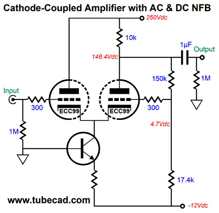
Speaking of the constant-current source, the ECC99's coupled cathodes sit so far up from ground potential, that we can terminate the constant-current source into ground. Another tube, such as the 12AT7, probably will require terminating the constant-current source to the -12Vdc power-supply rail; a 12AX7 certainly will. When the constant-current source terminates into the -12V power-supply rail, we need to add a protection diode. We can use the -12V to create a constant-current source with just a resistor and NPN transistor.
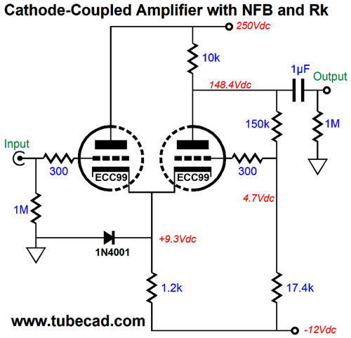
The transistor's emitter will be about 0.7V negative relative to ground. Thus, to find the required resistor value, we use the following formula: Re = (12 – 0.7)/I For example, if we seek an 18mA constant-current source, we would use 627-ohm emitter resistor. (A 620-ohm resistor would be close enough.) Just about any small low-voltage NPN transistor can be used, such as the 2N2222, 2N3019, 2N3053, 2N4401… Of course, some disdain using any solid-state devices. So, for those so inclined, we can replace the constant-current source with a resistor.
The 1.2k cathode resistor will dissipate about 0.4W, so 1W should be used (or two 2.4k 1/2W resistors in parallel). The performance is only slightly impaired compared to using the constant-current source. The protection diode is needed to prevent the triode from seeing +12 volts from cathode to grid at startup, when the triodes have yet to conduct. Once the triodes are hot and conducting, the diode is no longer forward biased and drops out of the circuit.
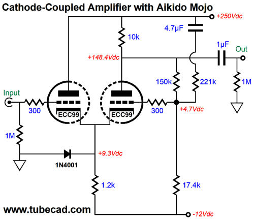
It has been a long slog, but we now arrive at the good stuff: Aikido mojo. The negative feedback helps increasing the PSRR, but we still have room for improvement. For example, the PSRR for the circuit above with the cathode resistor is only -8.4dB. Something better than -40dB would be preferred.
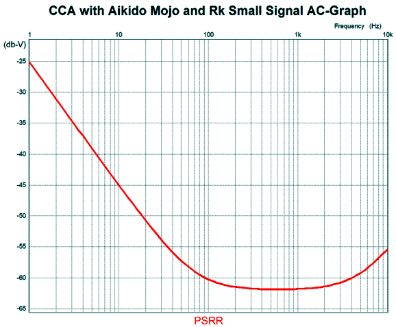
The added capacitor and resistor inject a small portion of the B+ voltage ripple into the right triode's grid, which the triode then amplifies and inverts at its plate, resulting in a deep power-supply noise null. In SPICE simulations, the PSRR came in at -60dB. The 4.7µF capacitor may seem excessively large in value, but it is the lowest value that I would use. The following SPICE-generated graph shows how far down in low-frequencies the null extends.
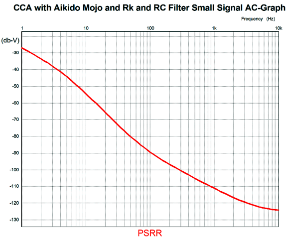
The key frequency is either 100Hz or 120Hz, as those are the frequencies of the ripple in countries where the wall voltage frequency is either 50Hz or 60Hz, respectively. We do not need to worry about the high-frequencies, as an RC filter with a good-sized decoupling capacitor will shunt away the high frequencies. For example, if each channel gets an RC filter made up of a 4.3k resistor and 10µF capacitor, the following plot-line results.
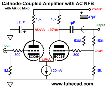
Without the Aikido mojo resistor and capacitor addition, the PSRR at 10Hz with the RC filter alone is only -37dB. This Aikido mojo technique can be added to the cathode-coupled amplifier with only AC negative feedback.
The 47µF capacitors must be that large to ensure a power-supply noise null. Moreover, the technique can be added to the version that uses a cathode resistor in place of a constant-current source.
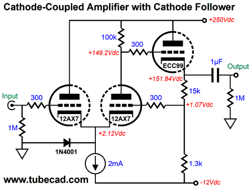
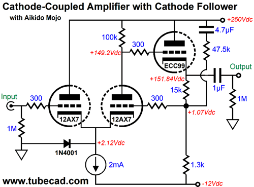
If we need a lower output impedance, we can add a cathode follower output stage.
A 12AX7 replaces the ECC99 in the cathode-coupled amplifier and the ECC99 triode powers the cathode-follower output stage. The DC negative feedback loop is made up of the two cathode resistors used in the cathode follower. We can insert the Aikido mojo resistor and capacitor to improve the PSRR.
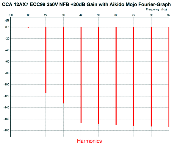
This circuit offers a lot of performance. Here is the Fourier plots for 1Vpk of output signal at 1kHz.
The distortion and output impedance (less than 30-ohms) are low and the PSRR is stellar. All that is missing is a suitable power supply.
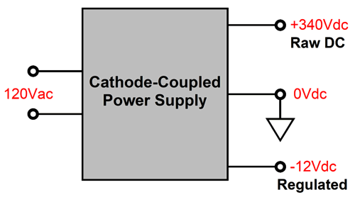
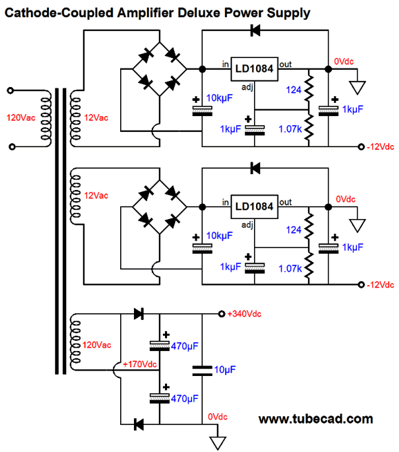
Dissimilar Bipolar Power Supply
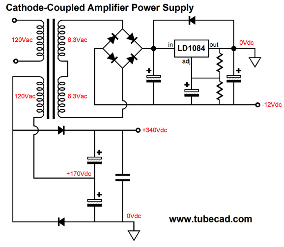
The largest flat-pack transformer I know of comes in a 48VA power rating. Thus, if its two secondaries each deliver 6Vac, their current rating will be 4A, which we can combine into a 12Vac @ 4A singe secondary. But as we will use one of the primaries to power the high-voltage portion of the power supply, the 4A rating should be halved to 2A. Of course, we would never get the full 2A after rectification and regulation. With a full-wave bridge rectifier, we need to divide the AC current rating by 1.8, which in this example yields 1.11A of DC current. Two ECC99 tubes will draw 0.8A amps of heater current.
Why didn't I use a negative voltage regulator, such as the LM337? The LD1084 is a far better regulator and by grounding its output, we effectively create a negative voltage regulator. Note that the 120Vac winding powers a voltage-doubler rectifier arrangement, which is a full-wave rectifier, appearances to the contrary. We will need two high-voltage reservoir capacitors, which should be 200V types. Actually, this setup works in our favor, as electrolytic capacitors are more volume-metrically efficient at lower voltage ratings. If we use a flat-pack transformer with 12Vac secondaries, we can give each ECC99 its own negative power-supply rail.
The assumption throughout has been that you live where 120Vac is the wall voltage. If you get 230Vac or 24Vac from your wall socket, then a flat-pack transformer with nominally 6Vac secondaries must be used, as their voltage will double with the 230Vac; in addition, a full-wave bridge rectifier arrangement will be needed for the high-voltage power supply.
Music Recommendation Hiromi's Spectrum As a college student, I enjoyed hearing live string-quartet performances at Tilden Park located in the Berkeley hills, which nourished my mind. I also reveled in rock concerts, which energized my body, but largely left my mind bereft of substance. At the Keystone Corner in San Francisco, however, both my body and mind delighted in the jazz performances. The string quartet fanciers sat frozen and fixed their attention like chess masters in a match. The rock fans jumped and bounced with the drum beats, as if ants were crawling up their legs. At one punk concert I attended, the band spit at the audience and the audience spit back and threw wild indiscriminate punches at each other. But in the small and intimate jazz club, the jazz lovers swayed and toe-tapped with the beat, while their minds sought the new directions the music would follow. In other words, mind and body were engaged. During the best jazz performances, so, too, was the soul, with emotions summoned, developed, and deeply felt. At its best, Jazz can overwhelm. When I saw that Tidal listed Hiromi's latest album, I knew that I would be dazzled by her technical ability. I didn't, however, expect the emotional payload of her ballads, such as "Whiteout," or the manifest genius of her her prolonged take on Gershwin's famous composition, "Rhapsody in Various Shades of Blue." Be sure to give this album a listen, a long listen, as it is over an hour long. Tidal offers the MQA version and the album was recorded by Telarc, so you know the sonics will be dazzling.
//JRB
User Guides for GlassWare Software
For those of you who still have old computers running Windows XP (32-bit) or any other Windows 32-bit OS, I have setup the download availability of my old old standards: Tube CAD, SE Amp CAD, and Audio Gadgets. The downloads are at the GlassWare-Yahoo store and the price is only $9.95 for each program. http://glass-ware.stores.yahoo.net/adsoffromgla.html So many have asked that I had to do it. WARNING: THESE THREE PROGRAMS WILL NOT RUN UNDER VISTA 64-Bit or WINDOWS 7 & 8 or any other 64-bit OS. I do plan on remaking all of these programs into 64-bit versions, but it will be a huge ordeal, as programming requires vast chunks of noise-free time, something very rare with children running about. Ideally, I would love to come out with versions that run on iPads and Android-OS tablets.
|
I know that some readers wish to avoid Patreon, so here is a PayPal button instead. Thanks. John Broskie
John Gives
Special Thanks to the Special 85
I am truly stunned and appreciative of their support. In addition I want to thank the following patrons:
All of your support makes a big difference. I would love to arrive at the point where creating my posts was my top priority of the day, not something that I have to steal time from other obligations to do. The more support I get, the higher up these posts move up in deserving attention.
If you have been reading my posts, you know that my lifetime goal is reaching post number one thousand. I have 510 more to go. My second goal was to gather 1,000 patrons. Well, that no longer seems possible to me, so I will shoot for a mighty 100 instead. Thus, I have 15 patrons to go. Help me get there.
Support the Tube CAD Journal & get an extremely powerful push-pull tube-amplifier simulator for TCJ Push-Pull Calculator
TCJ PPC Version 2 Improvements Rebuilt simulation engine *User definable
Download or CD ROM For more information, please visit our Web site : To purchase, please visit our Yahoo Store: |
|||


| www.tubecad.com Copyright © 1999-2020 GlassWare All Rights Reserved |