| John Broskie's Guide to Tube Circuit Analysis & Design |
13 August 2016 Post 391
Special Thanks If you have been reading my posts, you know that my lifetime goal is reaching post number one thousand. I have 609 more to go. I should easily be able to hit post 400 this year, as I only have eight more to go. My second goal is to gather 1,000 patrons. I have 956 patrons to go. If you enjoyed reading this post from me for the last 18 years, then you might consider becoming one of my patrons at Patreon.com. It would make a big difference to me. Thanks.
Electrostatic Headphone Amplifiers I wish I had an NOS 6SN7 for every time that some audiophile has told me that he doesn't like electrostatic headphones. At each occurrence, I then ask which tube-based electrostatic headphone amplifier he listened to, only to be invariably told that no tubes were used; just the solid-state electrostatic amplifier or step-up transformer was used. That's a shame, a dang shame. In order for electrostatic headphones to shine they must be paired with a high-quality tube electrostatic headphone amplifier. And since tubes are not that popular, electrostatic headphones can never be that popular, in spite of sounding fantastic. (It's interesting to note that back in the 1960s, when small, inefficient, but deep-bass producing, acoustic-suspension speakers were developed and sold, and which required far more power from our amplifiers, which allowed solid-state power amplifiers to push tube amplifiers out, one of the few groups of audiophiles who held steadfast to their tube amplifiers were those who owned Quad electrostatic speakers. These old standards allowed you to instantly hear what the slow, inefficient acoustic-suspension speakers had hid so well: just how dreadful those solid-state power amplifiers sounded. Shockingly bad, which no amount of 1960s nostalgia can undo. I dare you to listen to a highly esteemed solid-state amplifier from the late 1960s for more than an hour. Indeed, those sluggish speakers actually sounded more lively when paired with a scratchy, shrill, strident solid-state amplifier.)
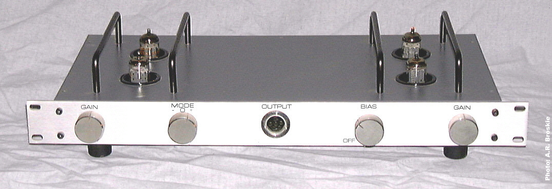
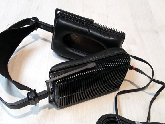
I have built so many electrostatic headphone amplifiers that I have lost count. Not all sounded good, however. My most ambitious efforts was, in fact, the worst sounding of the lot. I had decided to use pentodes instead of triodes, which at the time seemed a great idea. Yes, I got all the gain I desired, but none of the triode's sweetness. Even my hybrid electrostatic headphone amplifier that used a dual OpAmp to drive a triode output stage walked all over the pentode-based amplifier. Because I was so confident that the pentodes would work, I didn't bother to build a prototype, a huge mistake; instead, I went to all the trouble of making a beautifully slim enclosure filled with elaborate metalwork and with horizontally mounted tubes. It eventually ended up in landfill, but the bad taste still lingers. Another problem I ran into was singing capacitors. Some capacitors would hum and sing along with the music, as they became faux electrostatic loudspeakers in miniature. When everything lined up, however, the sound coming out of my Stax electrostatic headphones (the Lambda Pros) was stunning.
A friend of mine, who was an intense music lover, but not an audiophile, listened to them with my best tube-based electrostatic headphone amplifier and he proclaimed after a two-hour listen session with obvious heartfelt sincerity that this had been the finest musical reproduction that he had ever heard in his life, as he could now hear so much musical details that had eluded him in spite of hearing the same album hundreds of times before. In other words, I am an unabashed electrostatic headphone partisan. Yes, there are some fantastic dynamic headphones, but they cost a fortune, not that electrostatic headphones are cheap; besides, the low-impedance, low efficiency dynamic headphones are hard to drive with tubes, as they require low voltage and high current.
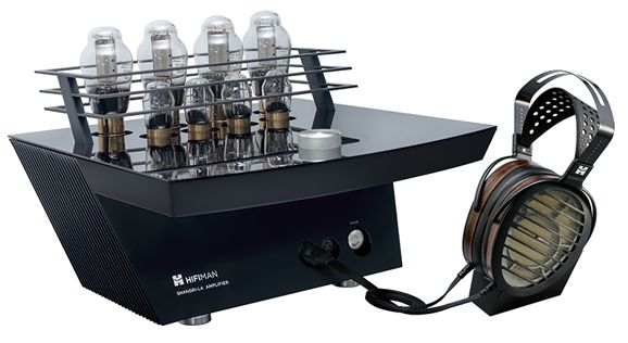
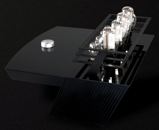
Well, I was reading the glowing review by Chris Martins of the literally glowing HiFiMAN Shangri-La headphones and electrostatic tube amplifier system (a mere $50,000) in the latest issue of HiFi+ magazine, a magazine that I always enjoy reading, when I came upon this sentence:
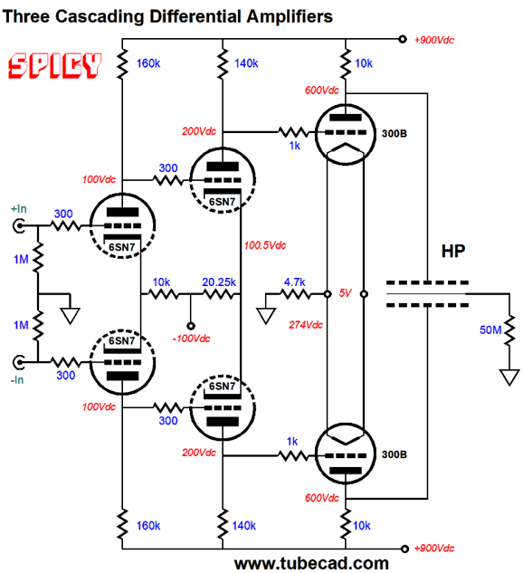
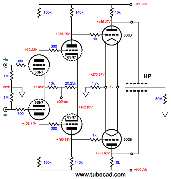
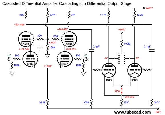
Interesting. The Shangri-La amplifier holds four 6SN7 and four 300B tubes. (The 300B tubes are custom-made for HiFiMAN, as low-microphonics is an essential feature, which, sadly, most 300B tubes do not offer.) This got me thinking about what the circuit topology must look like. My first impression was that the amplifier was DC coupled throughout, which is possible, but not easy to implement. I then put away the review and broke out my sketchpad. If we are allowed to use coupling capacitors and inter-stage transformers, then using two 6SN7 and two 300B tubes per channel grants us a vast array of potential circuits. In contrast, DC coupling throughout bestows only but one possible topology: three cascading long-tailed differential amplifiers, as shown below.
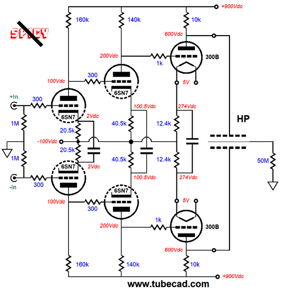
Note the "Spicy" icon, which denotes a circuit that works beautifully in SPICE, but seldom works well in reality. Get used to this icon, as I plan on using the "Spicy" icon in all future schematic that earn/necessitate it. What makes this circuit so spicy? In everyday, harsh reality, getting the plate voltages to match in the first stage will require some luck; then getting the final set of plate voltages to match will require divine intervention, as each cascading stage adds both AC and DC gain. In other words, it is unlikely that both 300B output tubes would see the same DC grid voltage in an actually built circuit that uses 1% resistors and real triode tubes. And even if the tubes were all hand-picked after extensive burn-in and testing at the factory, there is no guarantee that the strict DC balance will survive a month from now. In other words, I doubted that this was the topology that HiFiMAN used. Indeed, I would have dismissed it immediately, if it weren't for one specification given for the Shangri-La amplifier—namely, the polarizing voltage for the electrostatic headphones. An oddly ambiguous 550V to 650V is given. One hundred volts is a lot of latitude. The only possible excuse I could think of was that the 300B plates might differ in plate voltage by that much and that the polarizing voltage was effectively created by the stators sitting at between 550V to 650V, with 600Vdc being the target voltage, and the diaphragm being tied to either the B+ voltage or ground through a huge valued resistor, say 100M. One thought I soon had was that just which parts are in the signal path is a matter of much debate. Perhaps, only obvious coupling capacitors were excluded, not those whose purpose most audiophiles do not understand. For example, in the following schematic we see three capacitors being used to AC couple the cathodes in each differential amplifier stage. Do these extra capacitors count as being in the signal path?
My answer would be ABSOLUTELY YES. No doubt, others would disagree. What these three capacitors do is to prevent big plate voltage differences from developing. How's that possible? Note that each triode sees only one DC current path from the negative power-supply rail to the B+ voltage. Thus, even if the triode is a bit off spec, with its cathode-to-grid voltage being -2.12Vdc, rather than the tube manual's stated -1.92Vdc which allows 5mA of idle current to flow with 100V from cathode to plate, that 0.2V (or 10%) difference will prompt only the slightest change in target plate voltage. Here are the resulting voltages from SPICE simulations.
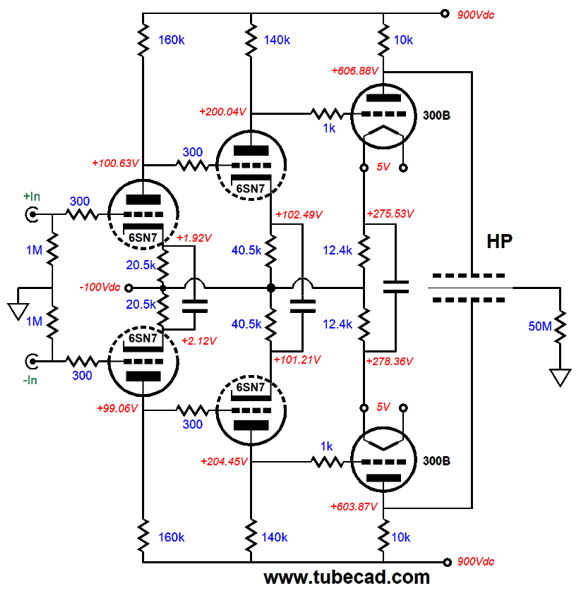
The bottom, leftmost 6SN7 triode is the wonky one. Roughly, only 3V of 300B plate voltage difference. Now, let's compare the results with the capacitor-free version.
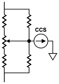
Note that 0.2V difference now results in a 267V plate voltage difference in the 300B output tubes. I know that many are wondering why potentiometers are not posistioned at the cathodes, as they would allow adjustment of the plate voltages. True, this would work, but I hate potentiometers, as they are prone to lose scraper contact and become scratchy and occasionally exhibit diode effects—none of which is desreable in an audio circuit. If you have to use a potentiometer, then use this improved setup, as the four added resitors allow for more precise and limited adjustment and a signal path should the potentiometer's scraper lose contact.
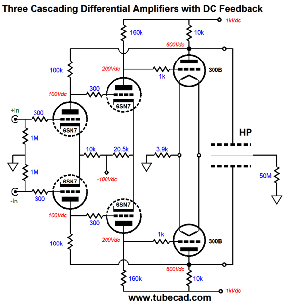
The more I thought about it, the more certain I was that neither of these topologies might be used in the HiFiMAN Shangri-La electrostatic headphone amplifier. One idea that came to me was that maybe they retained the three cascading differential amplifier stage, but used a DC negative feedback loop to equalize the output voltages. Here is one possibility that I came up with.
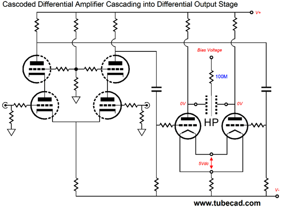
This arrangement provides DC feedback to the input stage, which helps keep the DC output voltages inline. We must pay the small cost of slightly lower gain, as 1.2Vpk of balanced input signal is required to summon forth 500Vpk of plate-to-plate output voltage swing, whereas the previous version required only 0.188Vpk. It was at this point that I decided to re-read the review. I quickly realized that the quote only stated that the 300B plate directly coupled to the headphone stators, not that no coupling capacitors or inter-stage-signal transformers were used in the rest of the electrostatic headphone amplifier. If we are allowed to add coupling capacitors, then one possibility is using a cascoded differential amplifier (aka, the Hedge circuit) to drive the 300B output tubes, as shown below.
This topology delivers enough gain so that only 1Vpk of balanced input signal is required to produce 500Vpk of plate-to-plate output voltage swing. Here the more-fleshed-out version.
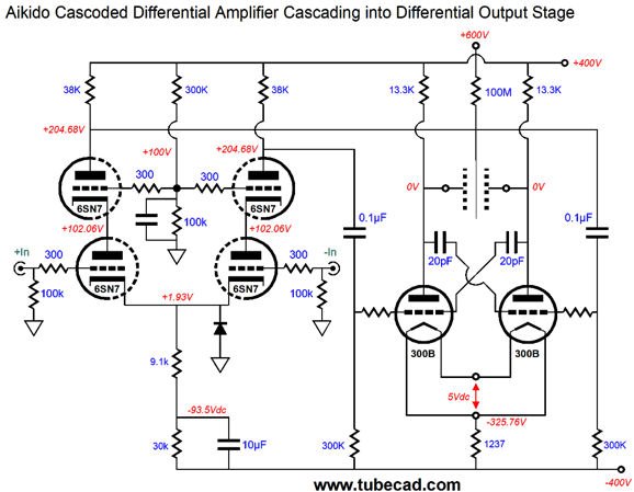
Now, here is the Aikido-mojo treatment and added safety diode.
The 10µF capacitor that shunts the 30k cathode resistor provides the Aikido PSRR enhancement, as it forces the same power-supply noise that appears at the negative power supply rail to appear at the topmost 6SN7 plates.
The two 300B and the shared cathode resistor work to create an impedance equal to their plate-load resistors, so a power-supply-noise null obtains at the outputs, assuming that the the positive and negative rails hold the exact same amount of ripple and in anti-phase, which should be the case.
Since the electrostatic headphones are intrinsically differential devices that see a balanced input signal, many would argue that no Aikido mojo is needed, as the power-supply noise will not be reproduced by the headphones. True enough. I have found, however, after listening to both approaches in my own amplifiers that the Aikido treatment sounds better. Why and how? It wasn't any less noisy, just slightly cleaner sounding. How this is possible might be explained by the output tubes not producing intermodulation distortion due to the power-supply noise being mixed with the music signal, as in the Aikido version the output triode grids no longer see the B+ voltage power-supply noise, only the negative power-supply rail noise, which their cathodes also see, so they null in the mix. On the other hand, I concede that I might have been fooling myself, as I wanted the improved PSRR version to sound better, so it seemed to sound better. At the same time, the audio placebo effect has a short life span with me, sometimes being only a minute or two long. In a way, I envy those audiophiles who can get week-long or even month-long rides out of the audio placebo effect. The two 20pF capacitors will confuse many, I fear. They extend the high-frequency bandwidth of the 300B-based output stage by undoing some of the Miller-effect capacitance. These work well, as long as we do not try to get greedy and use too large a value, which will turn the amplifier into an oscillator.
In summery, I have no idea of what is actually used in the HiFiMAN Shangri-La electrostatic tube amplifier, other than my guesses. If anyone knows Dr. Fang Bian, please send him the link to this post. I would love to know how close I got. (The only thing I would prefer is to actually hear the headphones and amplifier.) In addition, I must mention that while the tube circuitry is my first concern, there is a lot going on with this flagship product from its super thin, super high-tech diaphragms to the relay-based stepped attenuator. Be sure to follow the link to read all the details. //JRB
User Guides for GlassWare Software Since I am still getting e-mail asking how to buy these GlassWare software programs:
For those of you who still have old computers running Windows XP (32-bit) or any other Windows 32-bit OS, I have setup the download availability of my old old standards: Tube CAD, SE Amp CAD, and Audio Gadgets. The downloads are at the GlassWare-Yahoo store and the price is only $9.95 for each program. http://glass-ware.stores.yahoo.net/adsoffromgla.html So many have asked that I had to do it. WARNING: THESE THREE PROGRAMS WILL NOT RUN UNDER VISTA 64-Bit or WINDOWS 7 & 8 or any other 64-bit OS. One day, I do plan on remaking all of these programs into 64-bit versions, but it will be a huge ordeal, as programming requires vast chunks of noise-free time, something very rare with children running about. Ideally, I would love to come out with versions that run on iPads and Android-OS tablets.
//JRB |
Kit User Guide PDFs
And
High-quality, double-sided, extra thick, 2-oz traces, plated-through holes, dual sets of resistor pads and pads for two coupling capacitors. Stereo and mono, octal and 9-pin printed circuit boards available.
Designed by John Broskie & Made in USA Aikido PCBs for as little as $24 http://glass-ware.stores.yahoo.net/
The Tube CAD Journal's first companion program, TCJ Filter Design lets you design a filter or crossover (passive, OpAmp or tube) without having to check out thick textbooks from the library and without having to breakout the scientific calculator. This program's goal is to provide a quick and easy display not only of the frequency response, but also of the resistor and capacitor values for a passive and active filters and crossovers. TCJ Filter Design is easy to use, but not lightweight, holding over 60 different filter topologies and up to four filter alignments: While the program's main concern is active filters, solid-state and tube, it also does passive filters. In fact, it can be used to calculate passive crossovers for use with speakers by entering 8 ohms as the terminating resistance. Click on the image below to see the full screen capture.
Tube crossovers are a major part of this program; both buffered and un-buffered tube based filters along with mono-polar and bipolar power supply topologies are covered. Available on a CD-ROM and a downloadable version (4 Megabytes). |
||


| www.tubecad.com Copyright © 1999-2017 GlassWare All Rights Reserved |