| John Broskie's Guide to Tube Circuit Analysis & Design |
15 January 2020 Post Number 489
Mission Accomplished: Project Done
Unfortunately, I fell into the same trap I had fallen into so many times before: I put too much in too small a box. I have done this all my life. Just because you can doesn't mean you should. Last year, during the same month, I built my solid-state single-ended headphone amplifier and I promised myself that I would never shoehorn in all the parts in a tiny box.
Well, it turns out that a new year is a good time to make old mistakes.
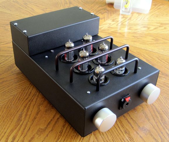
Single-Ended OTL Headphone Amplifier
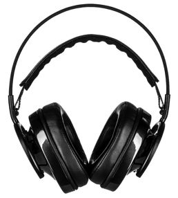
The Audioquest NightHawk headphones play plenty loud with 1Vpk of input signal, which translates into 20mW. I wanted some backup voltage headroom, so I aimed for 2Vpk (80mW). Since the output stage is class-A single-ended, the peak output current swing equals the idle current. If we divide 2V by 25-ohms, we get a peak current swing of 80mA. Desiring even more headroom, I decided to use 100mA as the idle current per channel. This may not sound like all that much current, but it is. First, there are two channels and the input and driver stages draw 10mA total, so the entire stereo headphone amplifier must draw 220mA, which against the raw B+ voltage of 170Vdc produces 37.4W of heat dissipation.
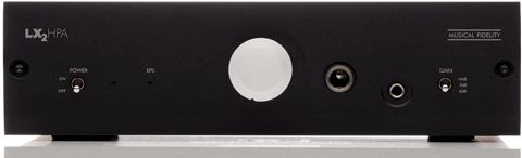
Actually, it is worse than that, as the heater elements draw about 2A against a raw DC power supply voltage of 16Vdc, which adds an additional 32W, bringing the total up to 69.4W. Imagine trapping a bright 70W light bulb in a metal box. In contrast, the Musical Fidelity LX2 HPA solid-state headphone amplifier accepts from an external power supply between 12Vdc to 24Vdc at 100mA, which means a worst-case of 2.4W.
Tubes equal heat. OTL and single-ended equals even more heat. Constant-current single-ended loading equals still more heat. Actually, it is worse still, as the transformers impose their own inefficiency. In other words, not all the power that goes into a transformer comes out its secondary. Why not? Long lengths of wire present DC resistance, which is called "Copper Loss;" and transformer cores suffer from eddy currents and hysteresis, which is called "Iron Loss." If you are pumping power in but not getting all of at the secondary, then the wasted power become extra heat.
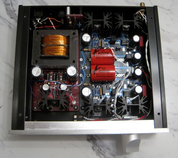
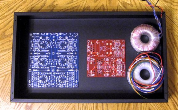
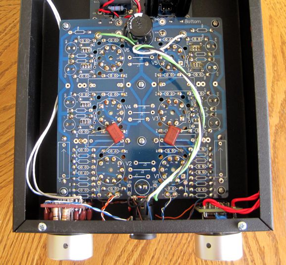
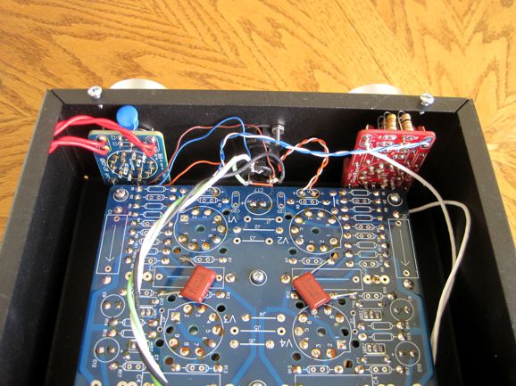
Here is the problem: the enclosure is relatively small. I had bought another 17in wide by 10in deep and 3in tall steel chassis from Hammond; but when I placed the SE AMP Noval PCB and PS-3 PCB and two 50VA toroids in the box, the box seemed largely empty. (The PS-1 would not work, as it cannot provide enough current.)
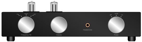
Here is one possible layout in the 17-inch wide enclosure.
Some demand a volume control. I demand a Tilt Control. We see both in the image above. I already had an 8in wide by 12in deep and 3in tall steel chassis also from Hammond. It looked tight, but possible.
Let's have some fun with math. (I am startled by how many hate math—and logic.) The 17-inch wide enclosure holds 510 cubic inches of volume; the 8in wide by 12in deep and 3in tall enclosure I used, 288 cubic inches. In other words, the 17-inch box offers 77% more volume. Another way to compare the boxes is surface area. The 17-inch wide enclosure presents 502 square inches of area; the 8in wide by 12in deep and 3in tall enclosure, 312 inches. The bigger box presents 60% more area. The more surface area, the better the box is at dissipating heat, as the convection air currents within the box work to distribute the heat throughout the box, which then radiates from the surface into the surrounding air. By the way, my using the smaller enclosure was only possible due to my still owning an old PS-3 power supply, which is smaller than the current version. In other words, do not try this project at home; use a bigger enclosure.
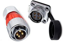
Another possibility is to use two 8in wide by 12in deep steel chassis, one for the headphone amplifier PCB and one for an external power supply. Yes, external power supplies are a pain, especially those that hold fixed umbilical cords. Two heavy boxes roped together becomes a knotty tangle without having four hands. On the other hand, fixing the cable to the headphone amplifier chassis and terminating it male plug into the female socket on the external power-supply box allows us to move each separately, without the fear of touching potentially live prongs. Note that I didn't specify the height of the smaller enclosures. Now, a 3-inch tall chassis grants us a lot of options in terms of part placement and heatsink height. In contrast, 2-inch chassis would look far sleeker, but limit our choices in part selection and layout. In either case, I would use a four-pin CB microphone connector jack and socket. Another possibility is the waterproof CNLINKO 4-pin male plug & female panel mount socket, which is rated for 500V and 20A and come with gold-plated pins.
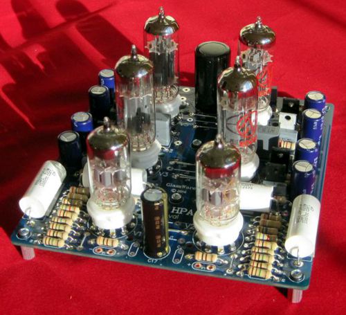
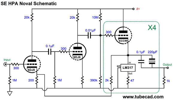
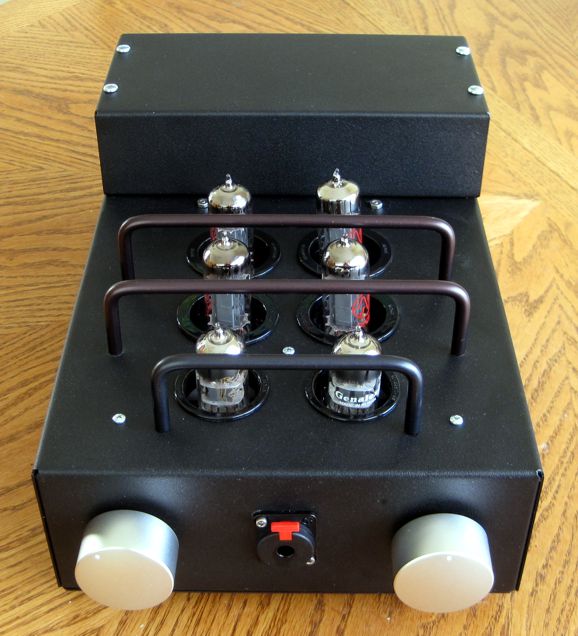
The circuit holds four cathode followers in parallel with four constant-current sources per channel, so each triode auto-biases.
The input stage consists of two grounded-cathode amplifier in cascade, with Aikido mojo selected operating points and part values. A negative feedback extends form the output to the input triode's cathode. The four output triode are the JJ ECC99 type and the two input and driver triodes are 6DJ8 types.
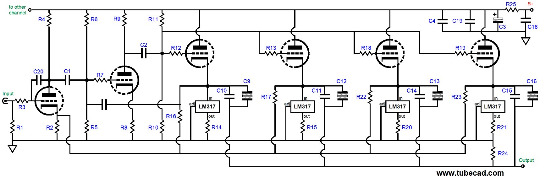
This is a simplified schematic. The actual schematic is more complicated, as each output triode feeds its own output coupling capacitor and negative feedback resistor.
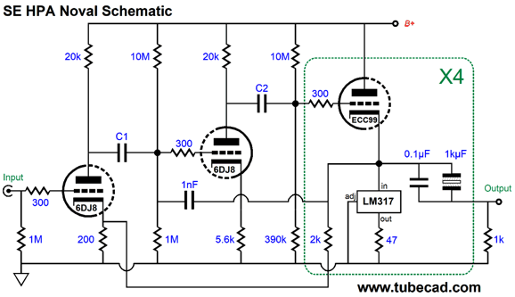
The amplifier's output is not phase inverted. The four 220µF output coupling capacitors are effectively in parallel, with a combined capacitance of 880µF, which allows bandwidth down to 11Hz with 16-ohm headphones. The capacitors are Panasonic non-polarized type and they sound quite good. In addition, each 220µ is bypassed by a 0.1µF polypropylene capacitor. The four 2k negative feedback resistors are also effectively in parallel and set a gain of 3 or 9.5dB. This may not seem like a sufficient amount of gain, yet it is. We do not need much gain at all. For example, the Musical Fidelity LX2 HPA mentioned earlier offers three gain levels, +6dB, 0dB, and -6dB. That's right negative 6dB. When I designed the PCB, I assumed that no volume control and no Tilt Control would be used, so I included capacitor C20 at the input to limit the high frequencies and ensure stability. I should have included pads for an optional stability capacitor for those who choose to use either a volume control or Tilt Control. In SPICE simulations, 1nF worked well. Only one capacitor is needed per channel.
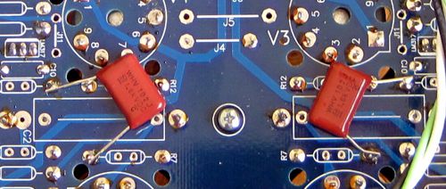
I had some large 1600V 1nF capacitors, which I soldered to the bottom of the PCB.
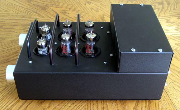
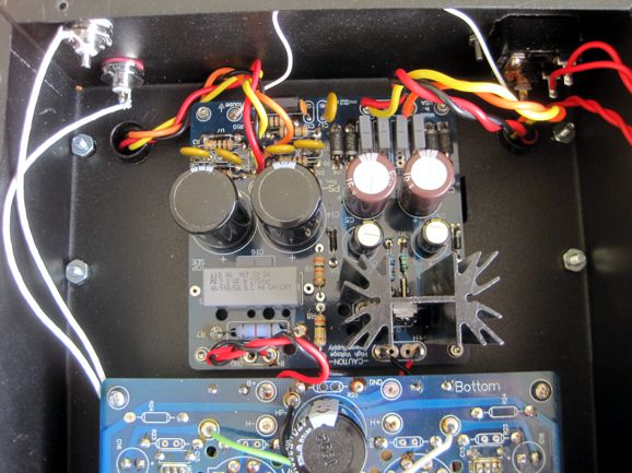
The voltage developed at the PS-3 power supply's rectifiers is about 170Vdc, which then leaves after the RC filter at about 160Vdc, which the RC filter on the SE AMP Noval PCB reduces to 150Vdc. I used two 50VA Triad toroid power transformers, enclosed in the box above. One holds a 120Vac @ 416mA secondary, while the other holds a 12Vac @ 4A secondary. If I could have found 60VA transformers or could fit 100VA transformers, I would have used them instead. Why? The four ECC99 tubes draw 1.6A at 12Vdc and the two 6DJ8 tubes draw 0.365mA at 12V (their heater elements are in series), making for total of about 2A. Divide 4A by 1.8 and you find the available DC current in a full-wave bridge rectifier configuration, about 2.2A. Not much headroom—or is it. The transformers are specified as being useable with either 50Hz or 60Hz wall voltage frequencies. Since I live in the USA, a 60Hz country, the transformer should at least be able to sustain 1.2 times as much power. How so? The lower the frequency, the bigger the transformer must be to achieve the same VA rating; and as 60Hz/50Hz equals 1.2, we should be able to get 1.2 times more power out of the transformer. The reality is that the two transformers still run hotter than I like. I can still touch them and not leave skin behind, but I would prefer cooler transformers. The workaround is to vent the top box. In fact, I am thinking of adding a DC fan to the amplifier, which would blow cool air into the bottom chassis and then up into the top box.
The headphone amplifier does not hold a volume control; instead, it holds a five-position Tilt-Control and a three-position power switch that offers mute at its center position. This is a hard mute that shorts the output to ground. All headphone amplifiers should hold a mute switch, as they come in so handy when you think you hear the phone ring or someone calling you. In addition, I like to protect the headphones at turn-on and turn-off, which the hard mute achieves, as it persists in the off position.
How does it sound? Very tube like and very single-ended. It struck me that single-ended is feminine, sounding seductive and soothing; and push-pull is masculine, sounding strident and showy. Think about this: the reason so many dislike listening to headphones might be because they have only listened to solid-state, push-pull amplifiers with headphones. Few, have ever heard any single-ended power amplifier, but fewer still have heard a single-ended headphone amplifier. (In twenty years time, the above paragraph will make no sense, as dictionaries will be rewritten and under the word "feminine" the definition will read: "Characterized by or possessing qualities generally attributed to a woman, such as immense physical strength and courage, valor, vigor, potency, drive, energy, leadership, and intellectual and cultural accomplishment." Under "masculine," we will read, "gentile, nurturing, comforting, and suportive"... "the weaker gender, given to excessive emotion and moodiness"...) I gave the new headphone amplifier a serious six hour long listening session with four different headphones and many different music genres. It was only after six hours of acute listening did I feel that I knew what the headphone amplifier sounded like. How anyone at the Can Jam or an audio salon, having spent all of thirty seconds listening, can hope to get a good feel for a headphone amplifier's sound is beyond me. If we throw in some tube rolling, it could take days to come to solid conclusions. Speaking of tubes, I can imagine some opting for less heat by using four 12AU7 output tubes. A 12AU7 draws about a third of the heater current that an ECC99 does. Another possible output tube would be the 12BH7, whose heater draws twice the current of a 12AU7, but does sport a 3.5W plate dissipation and can sustain far more cathode current. Ultimately, much depends on the headphones you plan on driving. The 300-ohm headphones from Sennheiser do not require high current, but do demand higher voltage swings. Some 50-ohm planar headphones require both voltage and current. With the ECC99 output tubes and the 25mA idle current flow per triode, we can get 5Vpk voltage swings and 250mW of power into the 50-ohm load impedance. Grado 32-ohm headphones play plenty loud with 1Vpk (15.6mW), so 2Vpk would provide a good amount of headroom. If we divide 2V by 32-ohms we get 62.5mA peak of current swing, so each triode in the SE output stage must idle at least 16mA. Heck, we could use four 6DJ8s and B+ voltage of only 100Vdc and still not exceed the tube's limits. Another possible output tube is the 6H30. With a B+ voltage 110Vdc, we could run an idle current of 35mA per triode. One tube that will not work, due to its different pin-out, is the 5687. As soon as I am done writing the user manual, I will start selling the PCBs and part kits.
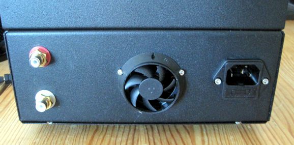
Breaking News
Well, I hooked it up to a 9-volt battery and it was amazingly quiet; two feet away, I could barely hear it. But if you have any experience with fans, you will know that situation can and will change. For example, some fans make more noise when slightly tilted. In addition, once the air flow encounters obstacles, new noises will arise. One trick that I have used many times is to purposely use a lower voltage. For example, I have used 230Vac fans with my 120Vac wall voltage, which reduces the spin to a fourth of it specified value and results in a huge decrease in noise. (Be sure to read the spec-sheet, as it often states the minimum starting voltage.)
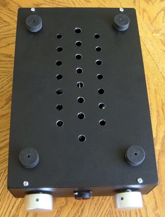
Once installed, the noise was much louder, sounding like a laptop fan. I cannot, however, hear it with the headphone on, but I still wish it were quieter. (The lowest-noise fans hold serrated fan edges, by the way.) It does work, as the chassis is much cooler now. I will have to try a non-perforated bottom panel, which will force the air up through top past the tubes.
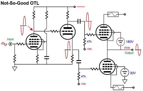
OTL Output Stages
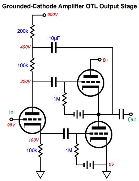
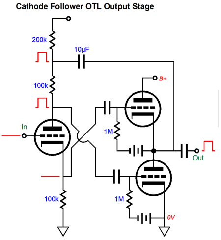
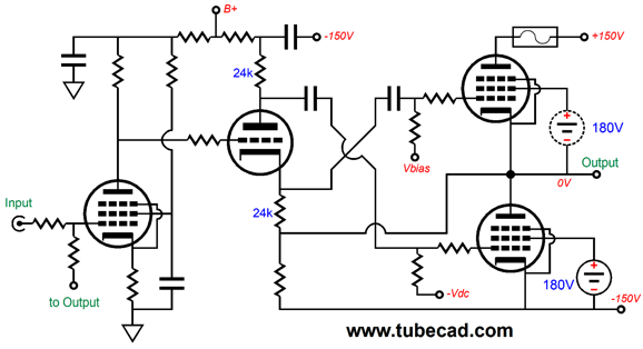
Another way of looking at it is that the top tube functioned as cathode follower, while the bottom functioned as a grounded-cathode amplifier. By returning the output signal to the split-load phase splitter, however, both output tubes functioned as grounded-cathode amplifiers.
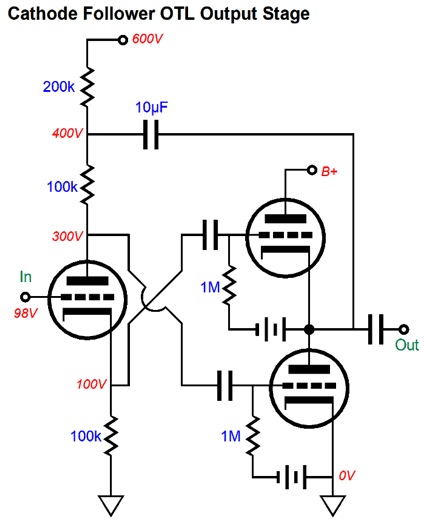
We could have, however, made both function as cathode followers. All that is required is to flip the outputs leaving the split-load phase splitter. (The best path to follow is to view the phase splitter and the OTL output stage as a single circuit.)
Both output tubes now function as cathode followers. If you are wondering if this is true, make some predictions. For example, if both function as grounded-cathode amplifiers, then wouldn't you expect some signal gain and an output impedance roughly equal to the plate resistance divided by two, or rp/2. In contrast, if both function as cathode follower buffers, then we would expect slightly less than unity gain and a low output impedance roughly equal to 1/2gm. Well, let's put both topologies in SPICE and see what results. We will use a 12AX7 in the split-load phase splitter and a 6DJ8 in the output stage.
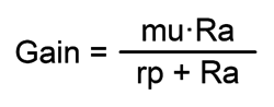
I tried using a constant-current source in place of the 1M resistor atop the phase splitter, but SPICE complained. (Mind you, I could have used a 10M resistor and a higher voltage power source. Ultimately, however, we run into SPICE's implicit 1G of resistance that attaches each node to ground, which makes for easier convergence in the SPICE engine, as some current always flows; SPICE is all about the movement of charge through a circuit.) The formula for a grounded-cathode amplifier's gain is simple, assuming that either fixed-bias or a bypassed cathode is used.
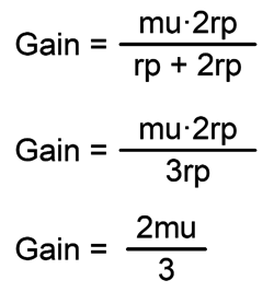
Okay, with no external load impedance, what is the value of Ra for the OTL output stage configured as grounded-cathode amplifiers? Well each triode effectively must view the other triode's plate resistance (rp) as it load. If we run the output stage in true class-B, wherein both output tubes are turned off at idle, then the answer would be rp. But since we are running something closer to class-A current flow, rp must be doubled, making the load impedance half as difficult, as we have twice the transconductance working for us. Now, we just have to solve for the gain with the load impedance being equal to twice the triode's rp.
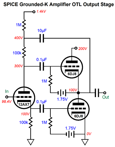
A 6DJ8 amplification factor (mu) is equal to 33 and 2/3 against 33 is the same as 3·11 against 2/3, or 22. In other words, my prediction is that the gain will come in at about 22. So, what were the results? Here is the output for the grounded-cathode amplifier configured output stage with an input signal of 1Vpk delivered to the split-load phase splitter's input.
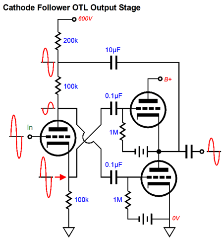
According to the graph plot, the gain is 22.866. My second prediction is that as both output tubes function as grounded-cathode amplifiers, the output impedance will be about 1450 ohms. Why? A grounded-cathode amplifier's output impedance is equal to the plate resistor's value in parallel with the triode's rp, which is about 2900 for a 6DJ8 with a cathode-top voltage of 100V and an idle current of 10mA. In SPICE simulations, the result was 1080 ohms. Why so low? It seems that the 12AX7-based split-load phase splitter partially worked to undo the pulse, as the bottom triode actually saw a tiny countering pulse signal. As cathode followers, the output impedance was 46 ohms, but no signal gain was realized. Speaking of cathode-follower output stages, let's apply the external pulse test to it, as it will reveal how both output triodes react equally in opposing it.
The 10µF capacitor relays the pulse to the top of the split-load phase splitter's plate resistor. Because the plate impedance is so high, almost all of the pulse remains at the bottom of the plate resistor, which is then relayed to the bottom output tube's grid, which prompts a huge increase in its cathode current flow, which in turn will buck the positive pulse. In contrast, the top output triode's grid sees a fixed DC voltage, but its cathode has become more positive due to the pulse relative to the grid, so it current conduction falls, which also counters the positive pulse. Both output triode work equally to fight the pulse. Here are the signal relationships:
Note that no signal gain obtains at the output. Also note how both top and bottom output triodes see the same magnitude of anti-phase signals relative to their cathodes, not ground. The output triode's sees a bigger signal at is grid, but its cathode also sees an in-phase signal. When we subtract the cathode signal from the grid signal, the remainder is equal in magnitude to what the bottom triode experiences. In my last post, we saw the OTL with a pentode input stage, followed by a split-load phase splitter, then the output stage configured as a grounded-cathode amplifiers. Can we switch the configuration to cathode follower? We can, but we can no longer use the same negative feedback setup
The input stage inverts the signal's phase, but the phase splitter no longer does, so the entire amplifier is an inverting type, so we must use the inverting feedback arrangement. Note that a mono-polar power supply and an output coupling capacitor is used. We cannot use a bipolar power supply, as the bottom output tube will not see the required negative rail ripple. In other words, a bipolar power supply will result in a worse PSRR.
PNP Split-Load Phase Splitter
Another possible workaround is to use a PNP transistor in the split-load phase splitter.
The output tubes function as cathode followers and the PSRR is fine. Let's add the bipolar power supply ripples.
Note that the bottom output triode sees the same amount of noise at both its cathode and grid, which means that the noise will not be treated as signal. Okay, let's now look at what happens when we force a positive pulse into the output.
The top output tube's grid still sees the same fixed DC voltage, but its cathode has been forced more positive, which makes the grid effectively more negative, so the current decreases. In contrast, the bottom output tube sees its grid go positive, so the current conduction increases. The result is that both triode equally buck the positive pulse. The big problem is finding a PNP transistor with a high enough breakdown voltage.
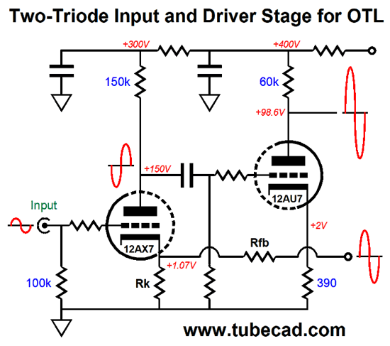
Even More OTL Design
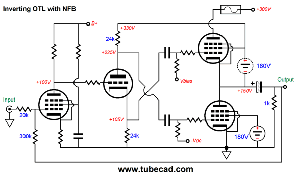
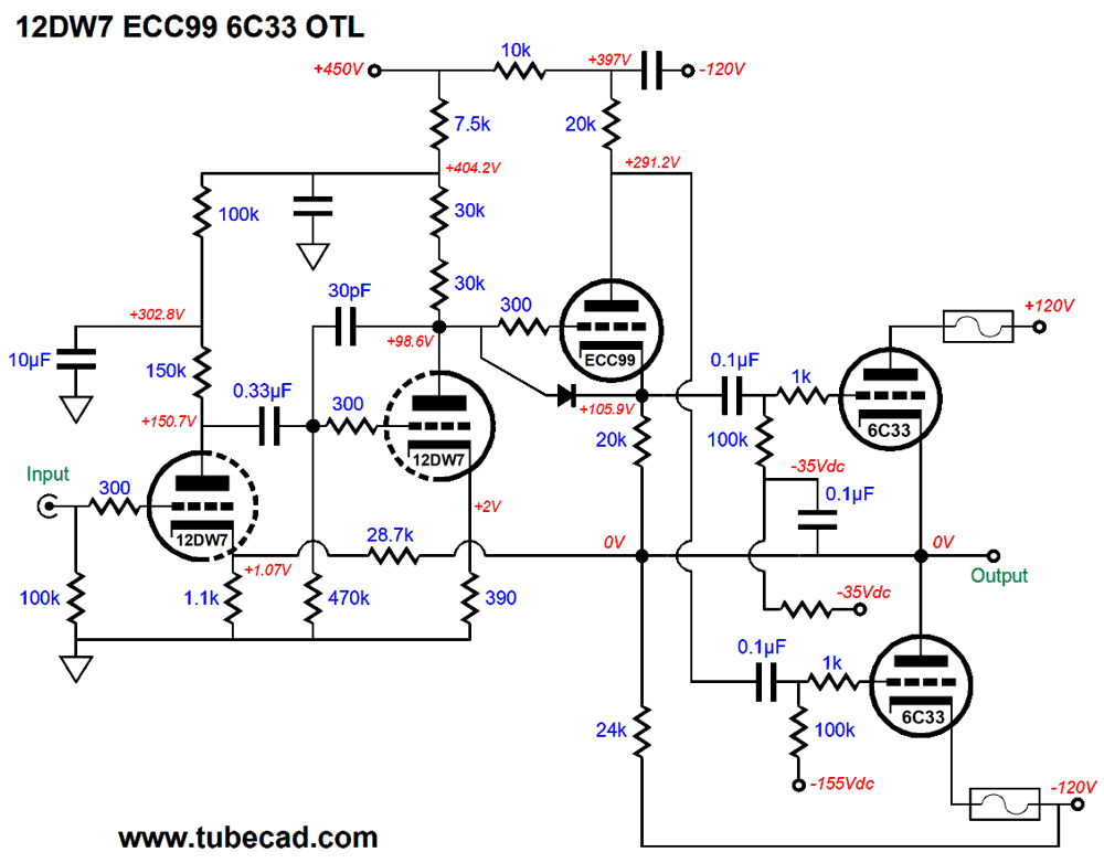
Plugging this frontend circuit into an OTL amplifier is easy enough.
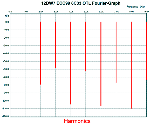
Yes, I added a few more parts to the mix, such as the 30pF capacitor and replacing the single 30k plate resistor with two 30k in series. If you are wondering why the 28.5k feedback resistor does not have the typical bypass capacitor, the answer is that the amplifier didn't need it in simulations. Indeed, I always view using this compensation capacitor in any amplifier as an admission of failure. Here is the SPICE-generated Fourier graph for 24Vpk into 8 ohms at 1kHz (36W).
The THD is quite low (almost as low as 0.1%), but the harmonic structure is very push-pull.
Music Recommendation: Three Crowns You know that I am going to point out that Tidal offers album (in MQA), so I don't know why I should mention it each time. Give it a listen.
//JRB
User Guides for GlassWare Software
For those of you who still have old computers running Windows XP (32-bit) or any other Windows 32-bit OS, I have setup the download availability of my old old standards: Tube CAD, SE Amp CAD, and Audio Gadgets. The downloads are at the GlassWare-Yahoo store and the price is only $9.95 for each program. http://glass-ware.stores.yahoo.net/adsoffromgla.html So many have asked that I had to do it. WARNING: THESE THREE PROGRAMS WILL NOT RUN UNDER VISTA 64-Bit or WINDOWS 7 & 8 or any other 64-bit OS. I do plan on remaking all of these programs into 64-bit versions, but it will be a huge ordeal, as programming requires vast chunks of noise-free time, something very rare with children running about. Ideally, I would love to come out with versions that run on iPads and Android-OS tablets.
|
I know that some readers wish to avoid Patreon, so here is a PayPal button instead. Thanks. John Broskie
John Gives
Special Thanks to the Special 84
I am truly stunned and appreciative of their support. In addition I want to thank the following patrons:
All of your support makes a big difference. I would love to arrive at the point where creating my posts was my top priority of the day, not something that I have to steal time from other obligations to do. The more support I get, the higher up these posts move up in deserving attention.
If you have been reading my posts, you know that my lifetime goal is reaching post number one thousand. I have 514 more to go. My second goal is to gather 1,000 patrons. I have 916 patrons to go. Help me get there.
Only $9.95
The Tube CAD Journal's first companion program, TCJ Filter Design lets you design a filter or crossover (passive, OpAmp or tube) without having to check out thick textbooks from the library and without having to breakout the scientific calculator. This program's goal is to provide a quick and easy display not only of the frequency response, but also of the resistor and capacitor values for a passive and active filters and crossovers. TCJ Filter Design is easy to use, but not lightweight, holding over 60 different filter topologies and up to four filter alignments: While the program's main concern is active filters, solid-state and tube, it also does passive filters. In fact, it can be used to calculate passive crossovers for use with speakers by entering 8 ohms as the terminating resistance. Click on the image below to see the full screen capture.
Tube crossovers are a major part of this program; both buffered and un-buffered tube based filters along with mono-polar and bipolar power supply topologies are covered. Available on a CD-ROM and a downloadable version (4 Megabytes). Download or CD ROM
|
|||


| www.tubecad.com Copyright © 1999-2020 GlassWare All Rights Reserved |