| John Broskie's Guide to Tube Circuit Analysis & Design |
| Post 232 26 May 2012
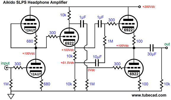
Hybrid Headphone Amplifier In addition, the split-load phase splitter's triode only gets 1/4th of the available B+ voltage. For example, if the B+ voltage is 160Vdc, then this triode would be allocated only 40Vdc of cathode-to-plate voltage—not much and, perhaps, too little, depending on the triode used. Of course the easy solution is to use a much higher B+ voltage; but the problem with easy solutions that they are so seldom easy. For example, as shown in the circuit below, the split-load phase splitter's triode sees a cathode-to-plate voltage of only 45Vdc and we might run into excessive output tube dissipation and we certainly would have to use smaller-valued power-supply capacitors, with a higher B+ voltage.
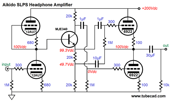
One workaround would be to use an NPN transistor in place of the split-load phase splitter's triode. Unlike a triode, a transistor can work with only few volts across its leads, which means that we can get much larger voltage swings out of the phase splitter. Moreover, the bigger voltage swings would allow us to use other output tubes, such as the 12B4 or 6AS7, which do require bigger grid-voltage swings, due to their relatively low transconductance.
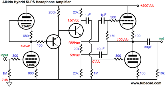
The MJE340 NPN transistor works much the same way the triode works in the split-load phase splitter, with its emitter following is base and its collector producing the anti-phase output signal. One huge difference, however, is that the transistor draws quite a bit of current from its base, whereas the triode doesn't. (With triodes we speak of their amplification factor; with transistors, current gain.) Thus, the transistor will tend to drag down the input stage. A workaround would be to use either a high-voltage FET (rare, but they do exist) or a high-voltage Darlington transistor (icky). The better approach is to use two cascaded transistors, a PNP and NPN type. Note that "cascaded" means one transistor following another, not "cascoded," which means one transitor atop another.
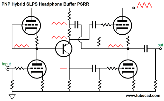
Because the PNP transistor (MJE350) draws so little current through its emitter (0.5mA), its base draws very little current indeed. Note how the the two cascaded emitter-to-base voltage drops add up to unity. Unity? For example, 100Vdc in and 100Vdc out. In fact, as long as the input tube holds well-matched triodes, the coupling capacitor to the top output tube could be removed. Since we added a PNP transistor type, we should move on to explore other uses of the PNP type, as the tube-world holds no equivalent; in other words, there's no P-type triode, alas. For example, what if we used a PNP type transistor in the phase-splitter position? In terms of output impedance and symmetrical current swings from top and bottom output triodes, this version works identically to the NPN-based version shown above. In terms of PSRR, however, its stinks.
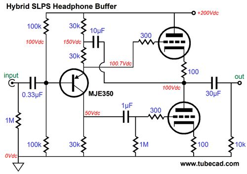
The input stage still halves the B+ ripple, but this split-load phase splitter does not present equal amounts of the power-supply noise at its two outputs. And since the push-pull output stage is a fundamentally a differential amplifier, the unequal amount of power-supply noise cascaded from the input stage is treated as audio signal and passed along to the output and your ears. Okay, so this was a dead end, but could we still take advantage of the PNP transistor type? Indeed, yes. For example, what if you already own a fine line-stage amplifier, one that puts out plenty of output voltage swing, then you could use the following circuit as a unity-gain headphone buffer, not an amplifier.
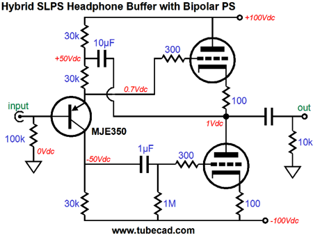
The assumption here is that the input signal source is noise-free and low in impedance. If the signal source resents a high impedance, however, then an additional input transistor will be needed, an NPN type. Converting this PNP topology into a bipolar-power-supply version is easy enough.
I like the look of this circuit. It would be fun to build such a circuit in an extruded enclosure, with a pair of 5687 or ECC99 tubes, with no volume control, although a mute switch would be convenient. Of course, we could replace the output triodes with MOSFETs or transistors, which would allow using the circuit in a small tin box with two 9V batteries. But before we search for applications, let's look into the all-solid-state topology further.
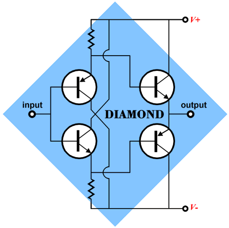
Diamonds Versus Triangles (Strictly speaking, a diamond circuit only requires that NPN and PNP types directly cascade, as is shown in the old Bur Brown OPA660 datasheet.)
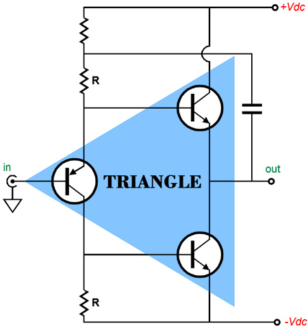
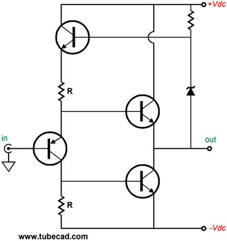
Well, now its time to behold a new unity-gain, solid-state buffer, the triangle buffer, which uses three transistors.
Note the similarity between this circuit and the hybrid circuit shown earlier, which used a PNP transistor in the split-load phase splitter configuration with the two output triodes and the bipolar power supply—triodes have been substituted by NPN transistors, but the circuit's functioning remains the same. A large-valued bootstrap capacitor tightly couples the output signal to the PNP-based phase splitter. If a positive going voltage pulse is forced on the output, this big capacitor relays the pulse to the PNP's emitter resistor, but the other end of this resistor is locked by the PNP transistor's emitter, so the emitter resistor undergoes an increase in current conduction, which also flows into the bottom collector resistor. In other words, the positive pulse also appears at the bottom NPN output transistor's base, causing the transistor to greatly increase its conduction, pulling down the buffer's output. In turn, the top NPN output transistor's base sees the positive pulse at its emitter, but its base is locked by the PNP transistor's emitter, which effectively makes the base more negative relative to the emitter, decreasing the top NPN transistor's conduction, causing the buffer's output to fall. Thus, both output transistors work equally to counter the pulse. By the way, we can invert all the transistors within a triangle, swapping NPNs for PNPs. High-voltage, power, PNP transistors are rare. Fortunately, the MJE5852, an 80W & 400V emitter-to-collector PNP transistor, is both cheap and readily available. 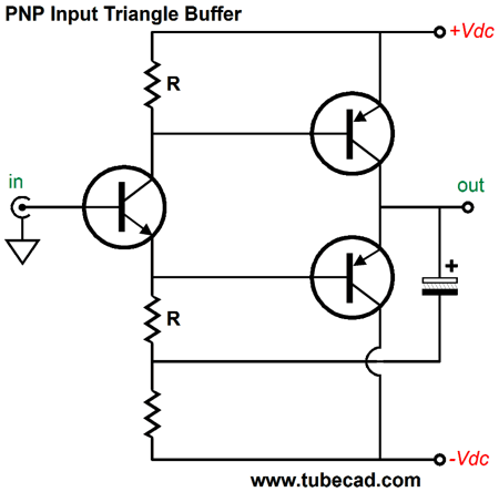
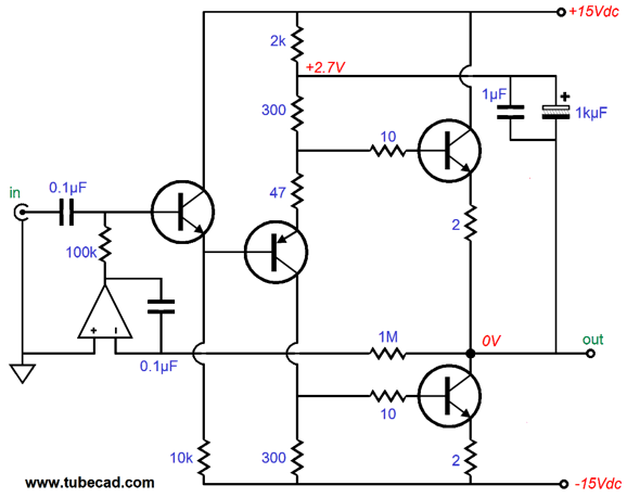
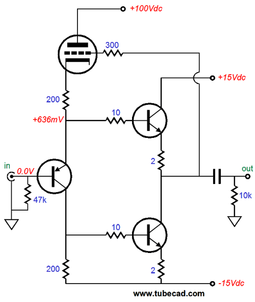
This version might be the better complement to tube circuit, as its non-linearity may counterbalance that of a triode's. Let's flesh out the previous triangle circuit, the PNP-input version, to see how it might actually be implemented.
Let go over the circuit's operation, in light of the added parts. Each output transistor gets its own 2-ohm emitter resistor, which both linearizes and protects its transistor from dead shorts at the output and thermal runaway. The 1kµF bootstrap capacitor tightly couples the output signal to the phase splitter. If a positive going voltage pulse is forced on the output, this 1kµF capacitor relays the pulse to the top of the 300-ohm resistor; but the other end of the resistor is terminated by the 47 0hm resistor and the PNP transistor's emitter, so the 300-ohm resistor undergoes an increase in current conduction, which is then shared by the bottom 300-ohm resistor, both being in the same current path. In other words, most of the positive pulse appears at the bottom NPN transistor's base (300/347 worth), causing the transistor to greatly increase its conduction, pulling down the buffer's output. In turn, the top NPN transistor's base sees only 47/300 of the pulse, but its emitter and its emitter resistor see 100% of the positive pulse, which decreases the top transistor's conduction, causing the buffer's output to fall. In other words, both output transistors work equally to buck the imposed pulse. Okay, why is there an output capacitor, when the output is only 10mV off from 0V? Safety and paranoia explain most of it. High-impedance headphones, say 300 ohms, might tolerate such a big DC offset, but I am not sure about all 16- or 32-ohm headphones. The workaround is to use an input coupling capacitor and a DC servo loop to keep the DC offset low.
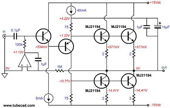
The OpAmp runs off the same +/-15V rails and it compares the DC voltage at the output with ground, making the required adjustments to keep the two in line with each other. Well, since we added an OpAmp, why not just use an OpAMp to drive the headphones? The triangle circuit can be made with big power transistors in its output stage, either TO-3 or TO-247 devices, which means that an idle current of 500mA is possible, which, in turn, means that peaks of 1A are possible. Now, 1A into 8 ohms equals 8Vpk, which equals 4W! This may be flea power for big speakers, but is massive power for 32-ohm headphones. Could a triangle power buffer actually be built to drive 8-ohm loudspeakers, rather than headphones? Indeed, as the following schematic shows. Note the inclusion of the two constant-current sources. In addition, note the four output transistors and the heavy idle current. Such a buffer yields a truly single-ended harmonic structure.
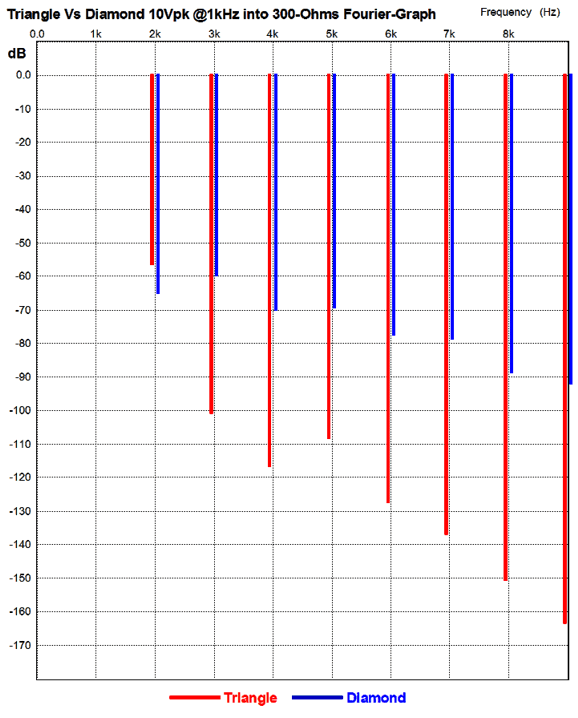
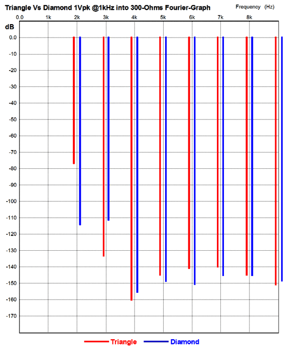
Okay, so why should I use the triangle circuit instead of a diamond circuit, which can also be made with equally big power transistors and could also drive speakers? Good question. It seems that the big advantage the diamond circuit holds over the triangle circuit is that no bootstrap capacitor is needed, which is great if you are making ICs. And the big advantage the triangle circuit seems to offer is one fewer transistors. Well, the following graph from a SPICE simulation reveals the real answer.
Note that the only harmonic that the diamond circuit beats the triangle circuit at is the 2nd. Also note the single-ened aspect of the triangle harmonic structure, in contrast to the push-pull structure from the diamond. I know which I would prefer to listen to. Slam dunk, right? Well, no. At 1Vpk @1kHz, the battle isn't so decisive.
Note how the diamond's 2nd harmonic is substantially lower than the triangle's. Slam dunk? No. Note how the triangle's 3rd harmonic is substantially lower than the diamond's. The ear rather likes the 2nd harmonic, but it dislikes intensely the 3rd harmonic, as it sounds deaden, lifeless. So, given the choice between more 2nd harmonic and less 3rd, I always choose less 3rd, even when the total harmonic distortion is greater. Considering that the common definition of an "audiophile" is someone who plays his music too dang loud, I am sure that most headphone-loving audiophiles would prefer listening to the triangle's vastly lower distortion at high levels.
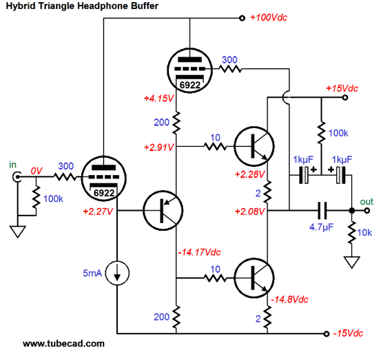
Hybrid Triangle Circuit
Since audio triodes most often come two to the tube envelope, we can use the extra triode as a high-impedance input buffer.
Of course, if we increased the bipolar rail voltages to +/-100Vdc, we could replace the two output transistors with triodes, making the buffer a closer approximation to pure-tube. Actually, +/40Vdc rails and a 6AS7 as the output tube might be fun.
Or we could replace both triodes with two transistors, which would require a voltage-dropping device, such as a zener or a diode string to give the base a higher voltage than the output.
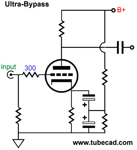
Electrolytic+ +citylortcelE I have no idea why this occurs; well, no idea that I would be willing to put into print. In a similar vein, I have found the sound from Panasonic non-polarized capacitors to be exceedingly fine. Perhaps, like transistors in a diamond configuration, electrolytic capacitors should always be be used in pairs. (I have found that even film capacitors sound better in parallel, with their ins and outs cross coupled.) Perhaps, the 100k polarizing resistor is not needed, but I have always found its inclusion a sonic good. (I remember reading that in radio work, the two-elecrolytic-capacitor-with-polarizing-resistor trick greatly increased the useful bandwidth of the capacitors, a very odd result, considering that it effectively doubles the capacitor's series inductance. Never forget that an electrolytic capacitor is an odd chemical-electro beast.) Some enterprising reader should rush to the patent office and patent the following setup, wherein a grounded-cathode amplifier has its cathode resistor bypassed by two electrolytic capacitor in series, positives connecting, polarized by a two-resistor voltage divider. The name? Need I say it, The Ultra Bypass, of course.
For example, if 5Vdc appeared at the cathode and 16V electrolytic capacitors were used, the polarizing voltage should be about 10Vdc. (Several years ago, I received an interesting e-mail, wherein the reader asked what I thought of a bold new topology, which was said to redefine the very standards by which other tube circuits were judged and which, invariably, were found wanting. It was a grounded-cathode amplifier that held two cathode resistors in series. My answer was that it would better to use two plate resistors in series, as it reduced the voltage-induced resistor distortion. Well, this polarized-two-capacitor trick might actually be worth the fanfare.)
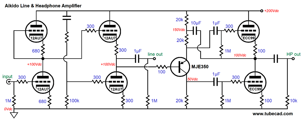
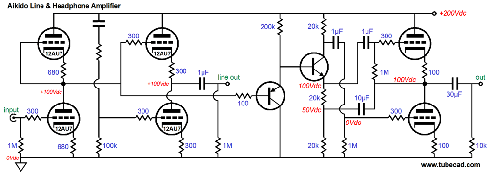
Aikido Line & Headphone Amplifier
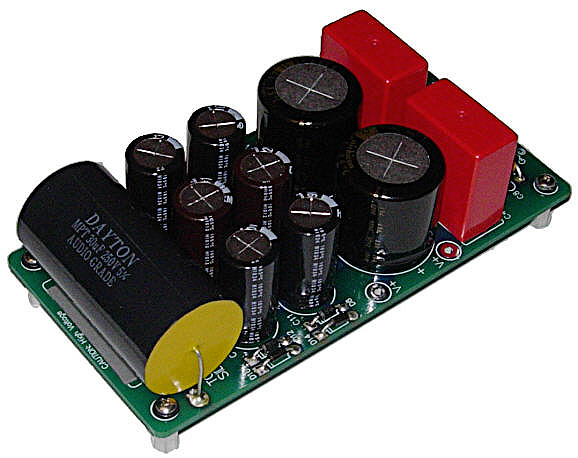
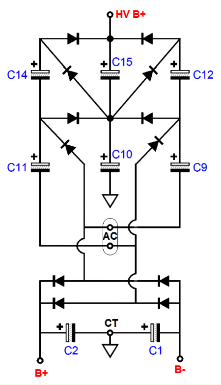
The PS-6 power supply presents three output voltages: a low-voltage bipolar output (up to +/-50Vdc) and a voltage quintupled high-voltage B+ output voltage roughly equal to five times the bipolar rail voltage. For example, if the rail voltages are +/-30V, the high-voltage B+ output voltage will be about 147Vdc; if the rail voltages are +/-15V, the high-voltage B+ output voltage will be about 73Vdc.
Or we could use the hybrid version of the triangle buffer with an Aikido line stage.
This Aikido offers two ouputs, one for line use and one for driving headphones. If we wish to tap earlier in the signal chain, the following variation would be worth examining.
Next Time
//JRB |
I know that some readers wish to avoid Patreon, so here is a PayPal button instead. Thanks.
John Broskie
E-mail from GlassWare Customers
High-quality, double-sided, extra thick, 2-oz traces, plated-through holes, dual sets of resistor pads and pads for two coupling capacitors. Stereo and mono, octal and 9-pin printed circuit boards available.  Aikido PCBs for as little as $24 http://glass-ware.stores.yahoo.net/
Support the Tube CAD Journal & get an extremely powerful push-pull tube-amplifier simulator for TCJ Push-Pull Calculator
TCJ PPC Version 2 Improvements Rebuilt simulation engine *User definable
Download or CD ROM For more information, please visit our Web site : To purchase, please visit our Yahoo Store: |
|||


| www.tubecad.com Copyright © 1999-2012 GlassWare All Rights Reserved |