| John Broskie's Guide to Tube Circuit Analysis & Design |
9 April 2005 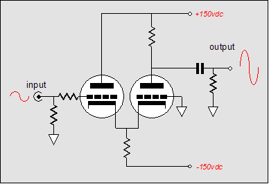
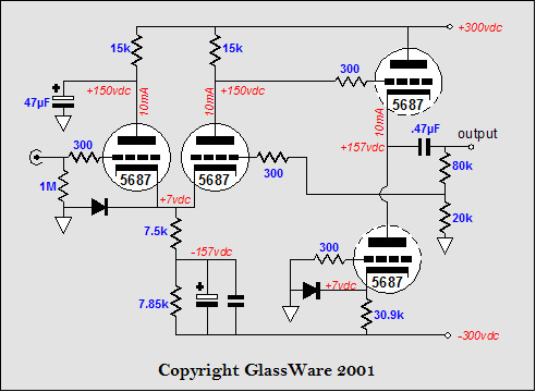
Common-cathode amplifier design ideas Moreover, it solves one of the great problems facing any tube-circuit designer: What to do with the second triode? Which second triode? The one that forms half of the pair in 6AS7, 6BX7, 6DJ8, 6FQ7, 6SL7, 6SN7, 12AT7, 12AU7, 12AX7, and 5687. The usual lazy-designer solution is to resort to the SRPP, as it requires smallest investment in either thought or extra parts. On the other hand, the common-cathode amplifier requires more: more careful design and more supporting elements, such as a negative power supply, and more resistors and capacitors. In fact, the common-cathode amplifier, right out of the box, does not even work. As shown in the schematic above, the amplifier suffers from the problem that one triode sees the full B+ voltage on its plate, while the other only sees what remains after the voltage drop across the plate resistor. These two different—substantially different—voltages require two different bias voltages to maintain the same idle current through each triode. The easiest solution is to place an additional plate resistor in the circuit. This resistor should be shunted to ground through a large-valued capacitor to ensure the benefits of the common-cathode amplifier. Many solder slingers do not bother adding the capacitor, introducing the Miller-effect capacitance and losing gain as a result. Laziness, stinginess, trendiness, and ignorance are the usual suspects. 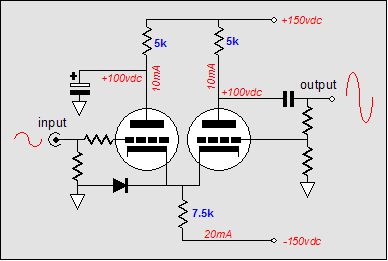
The common-cathode amplifier shown above is nicely fleshed out: the diode protects the triodes at turn-on, when the cathodes are cold and not conducting. Once the they are conducting, the diode falls out of the circuit, as it becomes reverse-biased and no longer conducts. The decoupling capacitor is in place, which will shield the input from a inverted gain at the plate. A feedback loop returns a small portion of the output signal to the inverting input, stabilizing the gain, lowering both distortion and output impedance. How it works 
No doubt, at the mention of “cathode follower,” a few readers have already grown nervous. "All cathode followers are bad, aren’t they?" they ask. "'Bad' in what sense?" I answer. If an amplifier sounds bad, it is distorting the signal in some way. Now, let’s say that the cathode follower is bending the signal in the wrong direction, the question is: What happens when this bent signal is used to drive a grounded-grid amplifier’s cathode input? If the grounded-grid amplifier were a perfect amplifier, a bent signal would be amplified bent. However, the grounded-grid amplifier, like all amplifiers, is not perfect; it bends just as much as the cathode follower does. Now, do the two circuits bend in the same direction or opposite directions? Since the common-cathode produces such a clean output, the answer can only be that they bend in opposite directions, so the grounded-grid amplifier undoes the cathode follower’s twist of the signal by twisting in the other direction. In fact, if the common-cathode amplifier is driven from the “wrong” input, the rightmost triode’s grid, while the leftmost triode’s grid is grounded, the distortion produced is lower than obtains with a comparable grounded-cathode amplifier. Why? The leftmost triode effectively becomes a cathode resistor, but not so nearly a linear a resistor as the worse-made resistor sold today. But since the amplifying triode is not perfectly linear, the triode as resistor counter balances the triode as amplifier to straighten the transfer curve. 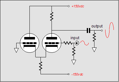
This configuration, however, does not shield the input from the Miller-effect capacitance. And what can be done with the leftmost grid other than just grounding it? One possibility is to build an SE power amplifier out of the common-cathode amplifier that uses the left triode’s grid to inject a small amount of B+ noise. A common-cathode SE power amplifier! 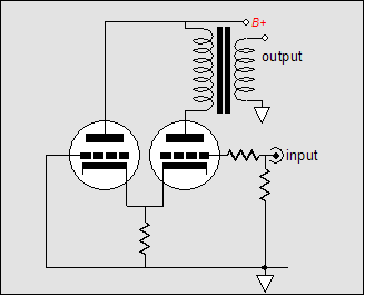
In the schematic above we see one input grounded and other receiving the input signal. Since the triode exhibits plate resistance, the power supply noise is voltage divided between the output transformer’s primary and the triode’s rp. Actually, in finer resolution, the rp is augmented by the other triode’s rp to become effectively 2rp, as long as the cathode resistor Rk is much larger than the rp. If Rk isn’t, then the following formula is needed: Thus, the voltage division is equal to rp' / (Rpri + rp'). Now any voltage signal superimposed on the transformer’s primary will be reflected to its secondary. So in order to have none of the power supply noise develop across the primary, all of the power supply noise must be present at the plate. Yes, this is counterintuitive; as usually we want the plate to be noise free, not noise filled. Considering that the primary impedance and the rp define a two-resistance voltage divider, how do we increase the plate’s ratio to 100%? The answer is found in the leftmost triode’s grid. If a precise amount of power supply noise is injected into this grid, it will be amplified at the rightmost triode’s plate in phase. Below is an example of such an arrangement. 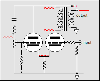
The potentiometer allows for careful noise nullifying at the loudspeaker connection. Of course, more supporting circuitry is required; for example, an input (and driver) stage. And the shared cathode resistor can be replaced with a constant-current source made from either a pentode or solid-state devices, such as three-pin voltage regulators or discrete transistors or MOSFETs. Many common-cathode amplifiers
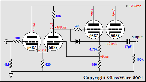
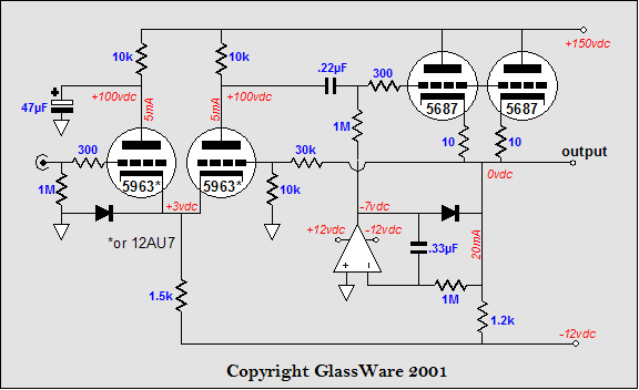
The circuit is surprisingly simple and effective. No negative power supply is used and only one coupling capacitor is used, albeit a large valued one, large enough to work into 300-ohm headphones, no less (for line amplifier use, a 0.47µF would suffice). The diode Tube-CAD-Journal-signature diode protects the cathode follower triodes at turn on (otherwise the grids would see +200 volts, while the cathodes would see 0 volts). A feedback loop provides a small amount global feedback, but not much, at least in AC terms, as the first stage offers little gain. In DC terms, however, the feedback keeps all the voltage relationships stable throughout the amplifier. If more feedback or greater gain is desired, a 12AX7 or 5751 or 6072 can replace the 5687 in the input stage. (A small negative power supply might be needed, say –12 volts, which would also serve to power the heaters.) The best solution might be to add an additional coupling capacitor at the input.
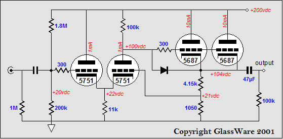
In this circuit, the input coupling capacitor allows us to use a two-resistor voltage divider to set a bias voltage higher than ground potential for the input stage. This move allows us to use a larger valued common-cathode resistor and to set the feedback ratio to yield a lower final gain. 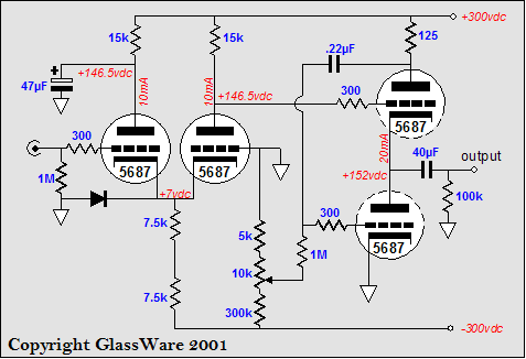
The circuit above holds a bipolar power supply and uses a White cathode follower to drive low impedance loads, such as headphones. A concealed attribute of this circuit is its superb low noise. As arranged, the power supply noise that presented to the White cathode follower is nulled at the output, as the schematic below demonstrates. 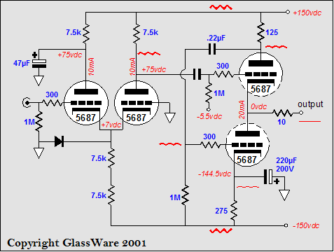
Since both top and bottom triodes see the same amount of power supply in-phase noise, they both vary their current conduction in unison, which means that as one tube pulls up the other pulls down, with no net shift in output voltage. A similar noise reduction technique is used below. This time countervailing power supply noise is injected into the common-cathode amplifier's cathode resistor, which then cancels the noise at its output. 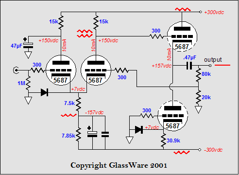 In this circuit, the cathode follower is loaded by a constant-current source made up of the triode and its relatively large cathode resistor. The effective impedance of this circuit is equal to rp + (mu +1)Rk, which in this example equals about 560k. The circuit below doubles up the cathode follower triodes and does away with the output coupling capacitor. The DC servo keeps the output referenced to ground and can step in and force the output to ground level, should the cathode follower tube fail or be pulled from its socket. 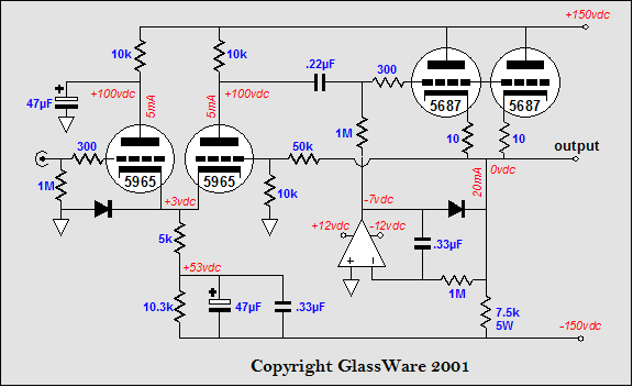
Of course, if regulated power supplies are used, then the need for noise canceling diminishes in importance. The following circuit assumes that clean power supply rails are in place and uses the same DC servo to maintain no DC offset.
Before anyone e-mails me, yes, indeed, the 1.5k and 1,2k resistors can be replaced with constant-current sources. I would use FET-based constant-current sources for both the front end and for the cathode follower load (although an OpAmp-based constant-current source may work just as well, for example an LM334, or even, an LM317) . A pause //JRB |
Support the Tube CAD Journal & get an extremely powerful tube-amplifier simulator for TCJ Push-Pull Calculator
TCJ PPC Version 2 Improvements Rebuilt simulation engine *User definable
Download or CD ROM For more information, please
visit our Web site : To purchase, please visit our Yahoo Store:
|
|||


| www.tubecad.com Copyright © 1999-2005 GlassWare All Rights Reserved |