| John Broskie's Guide to Tube Circuit Analysis & Design |
26 January 2021 Post Number 527
High-Voltage Shunt Regulators
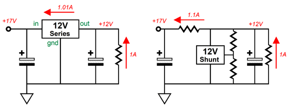
No compelling reason, but there are a few cautions. But first, let's start simply. Voltage regulators divide into two main types: series and shunt. Both find wide application, but the series is the most often used type, as it is usually the more efficient option. I have often likened the series regulator to a class-B output stage, which only draws heavy current when called upon. In addition, I have likened the shunt regulator to a single-ended output stage, as it must idle at the peak expected current variation.
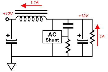
Here is a low-voltage example: a 12V series regulator rated for 1A of current flow, but unloaded draws only 10mA. In contrast, the equivalent shunt regulator must idle at 1.1A without a load, as the shunt requires a higher current flow to be effective. In other words, for the shunt to be able to regulate a fixed voltage, it must be able to both increase and decrease its current conduction enough to force the regulated voltage back on target. Assuming a voltage headroom of 5V for both regulator types, the unloaded series regulator at idle dissipates 0.17W; the unloaded shunt regulator, 17.17W. Another way of looking at the shunt and series regulator is that the series regulator is effectively a cascode circuit without a load resistor. While the series regulator fixes the B+ voltage the audio circuit sees, the regulator also passes along all the current-flow variation to the unregulated portion of the power supply.
If we placed a load resistor in series with the series regulator and the raw B+ portion of the power supply, we would get a big output signal. In contrast, the shunt regulator makes the audio circuit appear as a constant-current source to the raw B+ portion of the power supply, as the power supply sees a steady current draw.
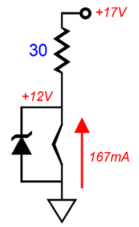
Not having all the audio signal-induced currents flow and mix can only improve the audio situation. Let's imagine the simplest shunt regulator possible, a 12V zener diode in parallel with a 12.6V heater element, both of which are in series with a single 30-ohm resistor that terminates into 17Vdc. With the tube in its socket, the series resistor experiences a current flow equal to 5V/30 or 167mA, producing a dissipation of 833mW. The heater sees a 12V voltage drop and a current flow of 143mA, while the zener sees the difference of 24mA, so it dissipates only 29mW of heat. With the tube missing from its socket, however, the zener must draw the entire 167mA of current flow and its dissipation rises to 2W. If the zener is rated for 5W of dissipation, this situation is no big deal.
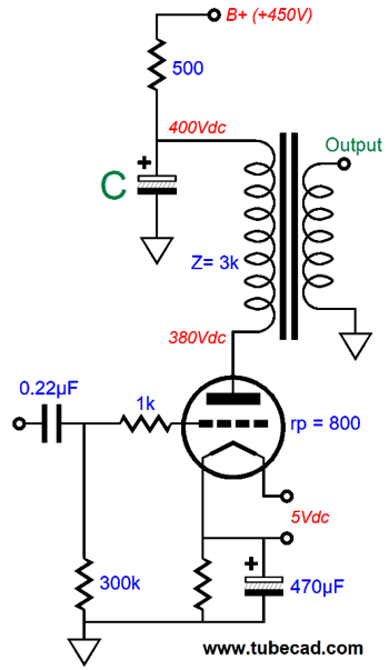
The question worth asking is how much wall-voltage variation can the zener tolerate and still maintain a fixed 12V of regulated voltage without exceeding its dissipation limit? The 5W dissipation limit implies a maximum current flow of 417mA, as 5W/12V equals 0.4166… amperes. Now, forcing this flow of current through the 30-ohm resistor provokes a voltage drop of 12.5V, which produces a resistor dissipation of 5.2W. We add 12.5V to the zener's 12V and get 24.5V. Since the design assumed 17Vdc of raw DC voltage, the over voltage is equal to 144%, so the wall-voltage can rise to 144% its nominal value. Assuming 117Vac in the USA, this equals a staggering 168.6Vac. Now, we find the minimum required wall voltage to sustain the 12Vdc voltage drop across the heater element. The zener's idle current flow 24mA sets the limit here, as the zener cannot draw negative current, falling only to zero flow. Inother words, we are going to assume that the zener is effectively out of the schematic. The heater's 12V voltage drop produces a current flow of 143mA, which against the 30-ohm series resistor develops a voltage drop of 4.29V. The design's target voltage drop was 5V, so the ratio between 4.29V and 5V results in a minimum wall-voltage drop no greater than 86%, as 4.29V/5V equals 0.857. Assuming a target wall voltage of 230Vac, the zener can regulate down to a wall-voltage droop to 197Vac. (It's always worth doing the math, as my guess was 210Vac, not 197Vac.) The tube's heater is a kind load, as it doesn't vary—other than when the tube is missing from its socket. Amplifiers do vary in their current conduction, some more so than others. Two solid-state push-pull 16W power amplifiers, one class-A and one class-AB, at peak output draw the same amount of current from the power supply, in this example, 2Apk assuming an 8-ohm load. The huge difference is that the class-AB amplifier idles at 100mA; the class-A amplifier, at 1A. The power supply sees a 1.9A variation in current draw, while the class-A amplifier provokes only a 1A variation, a variation that averages to 1A. That the average equals the idle current flow is huge, as it means that the power-supply reservoir capacitors can maintain a steady power-supply voltage, as the class-A amplifier's output stage appears as a constant-current source. The class-AB amplifier's power supply and its reservoir capacitors are not so lucky, as the wildly varying current demand taxes the capacitors and the power transformer. Let's say that we measure the current-draw variation of the class-A amplifier and find that average actually is 1.05A, not the ideal 1A that theory predicted. Well, that 50mA variation is ideally suited to shunt regulation, as the shunt regulator need only handle the 50mA variation, not the 1A of steady current flow. In contrast, a series regulator must see the entire 1.05A of current flow. Assuming a mono amplifier and a monopolar power supply rail voltage of 40Vdc and a regulated B+ voltage of 36Vdc, the series regulator would need to dissipate 4W at idle, as 40V – 36V equals 4V, which against the 1A of idle current equals 4W of heat. In contrast, the shunt regulator might idle at only 60mA, which against the B+ voltage of 36Vdc equals only 1.44W of heat. Let's examine a triode-based single-ended output stage.
How large should capacitor C be? Well, as a first approximation: infinitely large. A more realistic approach is to first determine the resistance that the capacitor faces. Seems easy enough; 500 ohms, right? No. We must combine primary impedance and the triode's plate resistance and then place this sum (3800) in parallel with the 500-ohm resistor, getting 440 ohms as the result. Next, divide 159155 by 440 ohms and then by 20Hz and get 18µF. This the very least amount of capacitance that we can get away with, so I would use ten times more, i.e. 180µF, with 150µF being close enough. The moral of the story is that shunt regulators should be paired with class-A amplifiers, either single-ended or push-pull, while series regulators should be used with class-B and class-AB amplifiers.
An added advantage shunt regulators hold over series regulators is that we can replace the shunt's series resistor with either a constant-current source or an inductor, which can greatly improve the regulator's PSRR. In addition, an ideal inductor displaces no DC voltage, so cannot produce any heat. Of course, real inductors (chokes) do present DCR (DC resistance) due to their being made from copper wire, which is not a perfect conductor; but most large chokes seldom present more than 1-ohm of resistance. Bear in mind, that with constant-current source replacement of the series resistor, we can still maintain DC voltage regulation with the shunt regulator. With the inductor replacement, however, we must settle for only AC regulation, not DC. In other words, the shunt regulator will work to scrub away AC voltage perturbations from the raw power supply rectifier ripple and signal-induced variations in the B+ voltage, but not strive to establish a fixed B+ voltage.
Regulators and Resistor Band-Aids
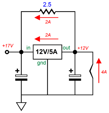
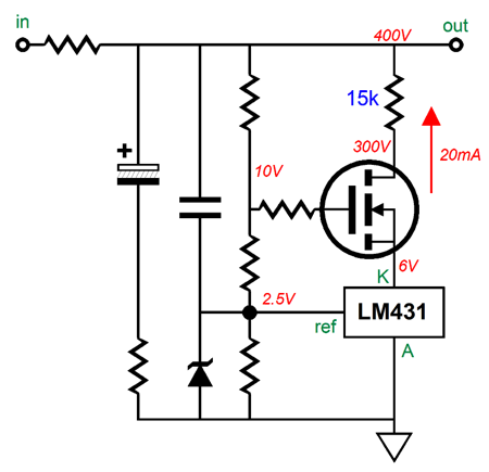
So what should the resistor's value and wattage be? We start with the raw B+ voltage of 17Vdc and subtract 12V, leaving us with 5V, which we divide by 2A and get the needed resistance of 2.5 ohms; next, we multiply 2A against the 5V voltage drop and get a dissipation of 10W. I like a safety margin of twofold, so I would use four 5W 10-ohm power resistors in parallel. With the shunt regulator, we place the added power resistor in series with the regulator, not in parallel. Imagine a high-voltage shunt regulator power supply of 400Vdc. The shunt regulator draws 20mA at idle. Without the added resistor, it dissipates 8W of heat, which we would like to see quartered. To get to 2W we must remove 300V of voltage displacement from the shunt regulator and give it to the added series resistor. Thus, we take 300V and divide it by 20mA and get 15k of resistance. Next, we multiply 300V by 0.02A and get a dissipation of 6W, so we could use a 10W 15k resistor. If we wished to get extra fancy, we would shunt the added resistor with a big capacitor or use three 100V-zener diodes in series in place of the resistor.
The LM431 can handle up to 100mA of current flow, so the 20mA is acceptable. Still, we do not want it to get overly hot. In addition, its voltage limit is 36V, so the N-MOSFET is needed. This is a cascoded arrangement, with the LM431 controlling the current flow through the MOSFET. The important point to be observed is that this resistor Band-Aid technique assumes a constant-current draw by the driven load. Heaters, for example, are expected to draw a fixed amount of current, as are single-ended amplifiers; class-AB amplifiers are not.
Pure-Tube Shunt Regulator
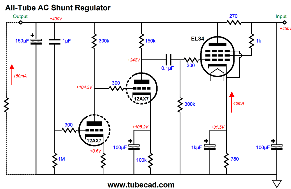
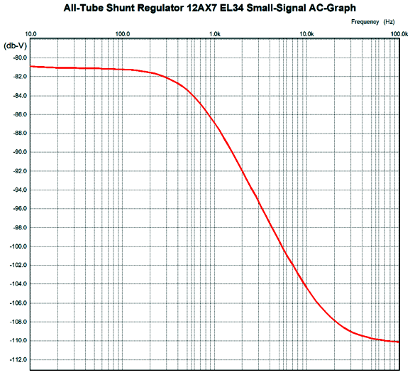
The two 12AX7 triodes in grounded-cathode amplifier configuration and in cascade create a huge signal gain, which then drives the EL34's grid, effectively increase the EL34's transconductance to something approaching what solid-state devices deliver. The EL34 dissipates about 15W and draws 40mA. In SPICE simulations, the output impedance was less than a third of an ohm at 1kHz. Its PSRR relative to the raw B+ voltage after the rectifiers was better than -80dB. Now, let's flesh out the design.
Note the 1-ohm resistor in series with the 150µF capacitor. Why is it there? As the shunt regulator's gain falls off at high frequencies, the regulator begins to resemble an inductor. What happens when we place an inductor in parallel with a capacitor? Answer: we get a resonate circuit.
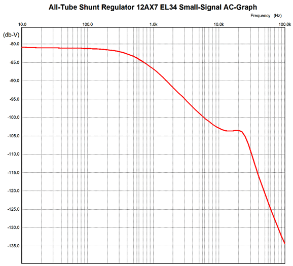
Note the excellent -80dB at 100Hz. To damp away the resonant peak at 20kHz, we place the 1-ohm resistor in series with the capacitor.
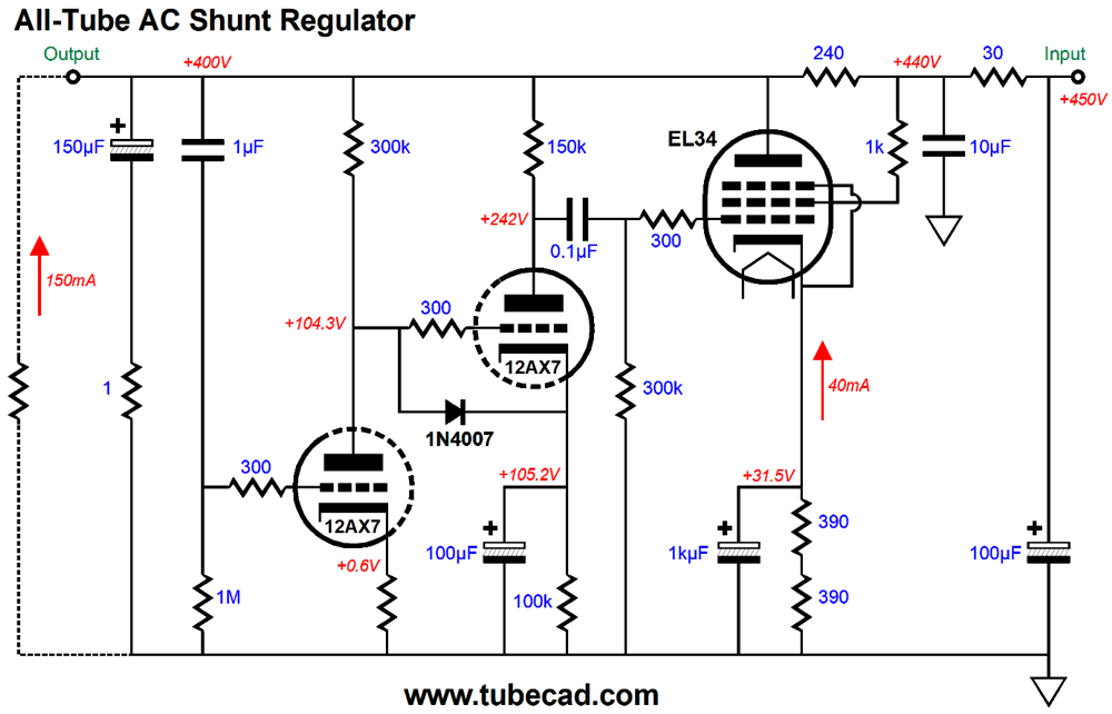
In the old days, this resistor wasn't needed, as electrolytic capacitors delivered such poor performance that their ESR (effective series resistance) was well over 1-ohm. Today, that's no longer the case. In fact, I am stunned by how much better capacitors have become in the last twenty years. For example, in decades past, I would never slam 400V across a never-used electrolytic capacitor. Instead, I would first place a 100k resistor in series with the electrolytic capacitor and form it first. Form, what is forming? Forming, also known as reforming, is the slow application of DC voltage to allow the electrolytic capacitor to form a layer of aluminum oxide on the surface of its internal foil. In decades past, this could take ten minutes; today, just seconds. In addition, in decades past, a charged high-voltage electrolytic capacitor would self-discharge in seconds; today, in many minutes, if not some hours, if not days. Also note the replacement of the EL34's cathode resistor with two resistors. I would actually use a constant-current source. Purists, of course, can stick to the cathode resistor. I would never be so pure, however, to forgo the 1N4007 diode, as it protects the second 12AX7 at turn-on, preventing the grid and cathode from being 400V apart in voltage. Not good. The RC filter made up of the 30-ohm resistor and 10µF are essential. I instinctively add RC filters to my own high-voltage regulators, whether they be series or shunt regulators, as they seem to prevent many problems, especially premature death of the regulator. The RC filter pre-filters the DC entering the regulator and slows the high-voltage ramp up to full voltage, which is far less of an issue with shunt regulators, but is a huge advantage with series regulators. I have found that as little as 10 ohms and 0.1µF can make a big difference.
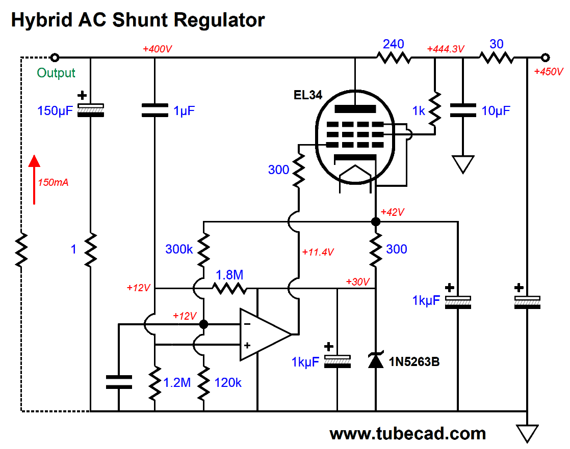
Hybrid Shunt Regulator
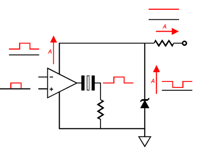
If this looks confusing, it might be due to the OpAmp's inputs seeming to be inverted. They are not. The EL34 effectively inverts the OpAmp's output, so the OpAmp's inverting input now becomes the hybrid amplifier's non-inverting input. An additional source of confusion might lie in the auto-bias feature that sets the EL34's idle current flow to 40mA. This was a freebie, so I took it. The way it works is that the two-resistor voltage divider defined by the 300k and 120k resistors force a 12V voltage drop across the 300-ohm cathode resistor. Thus, the idle current must equal 12V divided by 300 ohms, or 40mA. The OpAmp's non-inverting input sees all the B+ voltage ripple and signal-induced noise through the 1µF capacitor and compares it to the ground's absence of signal through the other 1µF capacitor. The OpAmp then amplifies this AC signal and delivers it to the EL34's grid. The EL34's response to the signal generates a countervailing current conduction that bucks the unwanted signal at the B+ voltage. Okay, let's add the missing details.
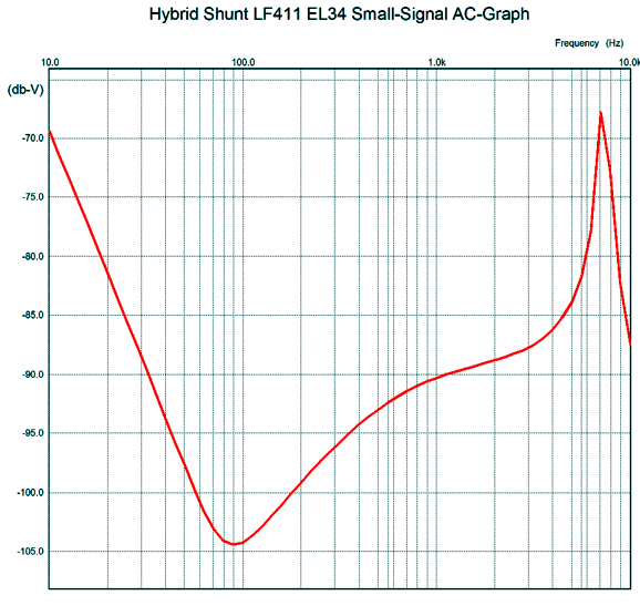
It might look much more complicated than the previous schematic but, essentially, it is the same. Rather than use two zeners in series, one 30V zener is used. The two resistors that attach to the OpAmp's non-inverting input effectively deliver the needed 12V DC voltage reference, so the 12V zener isn't needed. Let's look at what happens when we do not use a 1-ohm damping resistor in series with the 150µF capacitor.
That's a big, nasty resonant peak at 7kHz. Okay, now with the resistor in place.
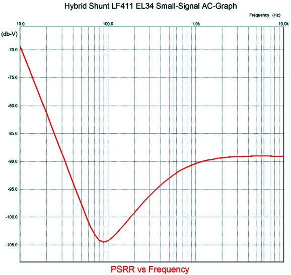
Nicely quelled. Use the resistor.
Music Recommendation: Thorvaldsdottir's Aerial Sadly, so much of avant-garde modern classical music does not bear repeated listening, which effectively disqualifies it from being "classical music." I remember reading in the CD booklet that came with Simon Rattle's CD, Jazz Album, that much of jazz does count as classical music, as it bears repeated listening over centuries.
No doubt whatsoever that great jazz albums, such as Take Five and Kind of Blue, will be listened to 300 years from now. Well, Thorvaldsdottir's composition, Aeriality, passes the listening longevity test, in my opinion, as I can easily imagine myself listening to again and again in the remaining decades I have left. //JRB
User Guides for GlassWare Software
For those of you who still have old computers running Windows XP (32-bit) or any other Windows 32-bit OS, I have setup the download availability of my old old standards: Tube CAD, SE Amp CAD, and Audio Gadgets. The downloads are at the GlassWare-Yahoo store and the price is only $9.95 for each program. http://glass-ware.stores.yahoo.net/adsoffromgla.html So many have asked that I had to do it. WARNING: THESE THREE PROGRAMS WILL NOT RUN UNDER VISTA 64-Bit or WINDOWS 7, 8, and 10 if the OS is not 32-bit or if the OS is 64-bit. I do plan on remaking all of these programs into 64-bit versions, but it will be a huge ordeal, as programming requires vast chunks of noise-free time, something very rare with children running about. Ideally, I would love to come out with versions that run on iPads and Android-OS tablets.
|
I know that some readers wish to avoid Patreon, so here is a PayPal donate button instead. Thanks. John Broskie
John Gives
Special Thanks to the Special 88
I am truly stunned and appreciative of their support. In addition I want to thank the following patrons:
All of your support makes a big difference. I would love to arrive at the point where creating my posts was my top priority of the day, not something that I have to steal time from other obligations to do. The more support I get, the higher up these posts move up in deserving attention.
If you have been reading my posts, you know that my lifetime goal is reaching post number one thousand. I have 473 more to go. My second goal is to gather 100 patrons. I have 22 patrons to go. Help me get there.
Only $9.95
The Tube CAD Journal's first companion program, TCJ Filter Design lets you design a filter or crossover (passive, OpAmp or tube) without having to check out thick textbooks from the library and without having to breakout the scientific calculator. This program's goal is to provide a quick and easy display not only of the frequency response, but also of the resistor and capacitor values for a passive and active filters and crossovers. TCJ Filter Design is easy to use, but not lightweight, holding over 60 different filter topologies and up to four filter alignments: While the program's main concern is active filters, solid-state and tube, it also does passive filters. In fact, it can be used to calculate passive crossovers for use with speakers by entering 8 ohms as the terminating resistance. Click on the image below to see the full screen capture.
Tube crossovers are a major part of this program; both buffered and un-buffered tube based filters along with mono-polar and bipolar power supply topologies are covered. Available on a CD-ROM and a downloadable version (4 Megabytes). Download or CD ROM
|
|||


| www.tubecad.com Copyright © 1999-2021 GlassWare All Rights Reserved |