| John Broskie's Guide to Tube Circuit Analysis & Design |
31 May 2014
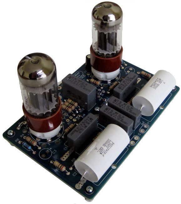
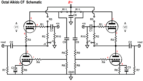
New Octal Aikido Cathode Follower My initial idea was to just remake the noval ACF PCB into an octal version, a relatively easy transformation. But upon some reflection, I realized that I could easily make an improved octal version. Improved? Yes, indeed. But first, let's review the stock Aikido cathode follower configuration.
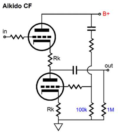
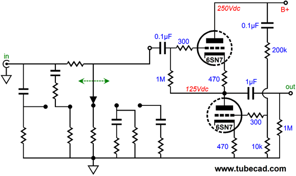
The ACF is basically the last half of the Aikido amplifier, a modified cathode follower buffer circuit that provides near unity gain and a low output impedance. This modified cathode follower scrubs away the power-supply noise from its output. This feat is accomplished by proactively injecting a small sample of the power-supply noise into the bottom triode's grid, which generates a countervailing current variation, which nulls the ripple from the output. In addition, the Aikido cathode follower produces lower distortion by using the triode’s own non-linearity against itself by providing a complementarily non-linear load for the top triode’s cathode. Okay, that was how it works, now we move on to what it could be used for. Passive line stages often prove inadequate, incapable of adequately driving high-capacitance cables or low-input impedances. I find this outcome quite paradoxical, as it is easier to believe that less must be more in terms of signal transmission, just as the telescope with the fewest lenses must present the clearest image. Yet, time after time, I have found adding a buffer stage, both solid-state- and tube-based buffers, readily outshines a passive setup, as the active buffer often imparts the missing heft and solidity missing from most passive setups, even with the added cost, noise, and distortion, which the active circuitry must necessarily bring to the mix. The difference isn't subtle. I expect, however, that most will use the octal ACF in series with an existing solid-state audio signal device, such as a CD player or DAC, rather than as unity-gain line-stage amplifier. If such is your plan, you might think about placing a GlassWare Tilt Control in front of the octal ACF, as it will allow some fantastic but subtle tonal changes. For example, with one click to towards a tilt to the highs, I can make HD650 sound better with rock and jazz music; conversely, with one click to towards a tilt to the lows, I can make Grado SR225 sound better with classical music. Amazing.
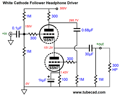
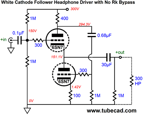
Even if your experience is different, as your existing phono stage or DAC can drive your amplifiers perfectly well, it is unlikely that it can drive high-impedance headphones, such as the 300-ohm types from Beyer and Sennheiser, such as the famous HD650, HD700, and HD800. This brings us to the new improvement on the octal ACF PCB missing from the noval PCB: the option of White cathode follower configuration, which only the octal ACF PCB allows as an option.
Mr. Eric White, the British inventor who worked for EMI, patented his famous White cathode follower in 1940 in England (GB564250), which was also patented in the USA in 1944 (US 2,358,428). His circuit is a unity-gain, push-pull buffer that accepts an unbalanced input signal and presents an unbalanced output. This feat of magic is performed by the top triode's plate resistor that functions current-sense resistor that experiences a variation in voltage drop corresponding to the variation in current conduction by the top triode. This variation in voltage drop becomes the input signal for the bottom triode, which responds in an anti-current phase fashion, creating a complementary, balanced push-pull operation by the two triodes. As the top triode conducts more, the bottom triode conducts equally less; as the top triode conducts less, the bottom triode conducts equally more. The result is class-A, push-pull operation that yields an output impedance half of what it would be with the same tube in a cathode follower and lower distortion. Moreover, the White cathode follower can deliver a peak output current swing into the load twice that of its idle current. The load is all important and its impedance must be factored into the calculation of the sense resistor’s value. Without the external load, the two triodes could not differ in current conduction, so no push-pull operation would be possible. Without the load, the sense resistor would not create the needed drive signal for the bottom triode. Assuming that the bottom triode’s cathode resistor is bypassed by a large-valued capacitor, the formula for the optimal sense resistor value is the same as the one used for the SRPP circuit: Rs = (rp + 2Rload)/mu For example, a 6SN7 with a cathode-to-plate voltage of 150V and 10mA idle current presents an plate resistance (rp) of about 7500 ohms and a mu of 22; thus, with a load impedance of 600 ohms, the sense resistor should equal (7500 + 1200)/22 or 395 ohms.
The bottom triode’s cathode resistor should be bypassed; if it's not, a slightly more complex formula will be needed and the sense resistor must necessarily go up in value, roughly: Rs = Rk + (rp + 2Rload)/mu The list of tubes that can be used in the octal ACF PCB is short: 6AS7, 6BL7, 6BX7, 6H30pi (the octal version of the 6H30), 6SL7, 6SN7, 12SX7 and all the substitutes for these tubes, such as the 6SU7, ECC33, and 5692. But for 99% of audiophiles, the 6SN7 is the best choice. But do not forget the odd heater variations, such as the 8SN7 and 12SN7.
The octal ACF PCB and kit is available now at the GlassWare-Yahoo store.
Hybrid Topologies
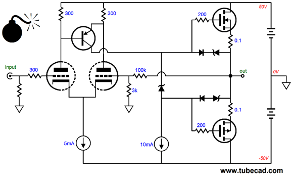
Well, my guess is that, much like Scheherazade, I could—over 1,001 days—create 1,000 new hybrid topologies—each of which would comply with the four rules that I had put forward for consideration in blog number 291, including the unspoken rule of not using any gratuitous SRPP stages. No doubt, some would prove too silly and other too whimsical—but a few just might be worth building; indeed, well worth building. What makes me so optimistic? Simply, there are many topologies and they all can be combined to create many more new topologies, so the odds are definitely in my favor. Thus, what irks me is that—in spite of this near infinite array of possible hybrid topologies—every other month I get an e-mail from an eager newbie that contains an SRPP tube stage driving a MOSFET-based output stage, presented with great fanfare and pride. So, as nod to Scheherazade, here is a non-SRPP hybrid design, a low-voltage hybrid design:
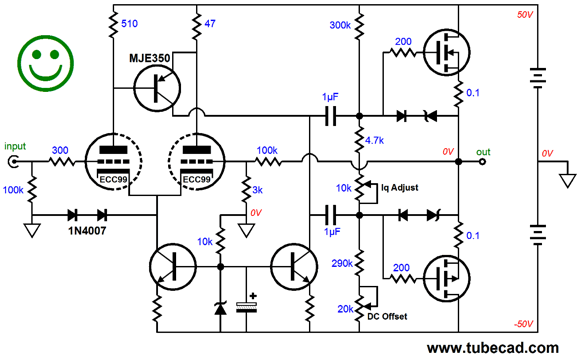
Note the relatively low rail voltages, only +/-50Vdc. The input tube, say a 6DJ8/E88CC/6922 or ECC99, sees a cathode-to-plate voltage of a little less than 50V, which while not all that high, is enough to get some decent current flow. Also note the Lender circuit, wherein the PNP transistor attaches to the two plate resistors. This topology creates an amplified, in-phase signal to drive the power MOSFETs. Finally, note the bomb icon. Why is it there? It denotes a major problem. Can you spot it? Think about what happens at startup, when the tube is cold and not conducting. What will the output voltage be? The answer is that the output will slam and stick to the negative rail, as the constant-current source will pull the output stage's output down, holding it down until the tube heats up and begins to conduct some current. In that elapsed time, your speakers can catch on fire. Never a good idea. One workaround might be to place constant-current source in series with the resistor that feeds the Lender circuit's constant-current-source load, as shown below. If the tube is not conducting, this setup prevents the NPN transistor from conducting. As the input tube begins to conduct, the constant-current source finds a current path to the B+ voltage and the 1k resistor begins to charge up the large-valued electrolytic capacitor, giving the NPN transistor's base a clean and steady fixed voltage.
So, where is the happy face? I still have a few fears; for example, what if the Lender circuit starts pulling up before its constant-current source catches up? Or, what happens at turn-off, does the constant-current source keep conducting while the tube cuts off? The RC filter that feeds the NPN transistors giveth but also taketh. In addition, at start-up, the CCS will pull the cathodes down to -50V, while the grids sit up at 0V. The following schematic shows a solution.
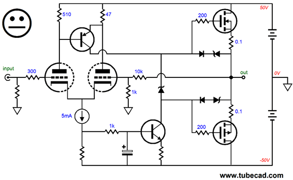
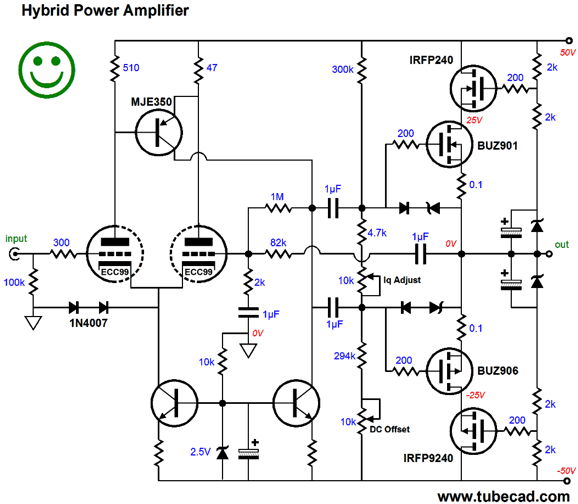
By using two internal coupling capacitors, we can sidestep these sorts of fears, as the output will center even without the input tube being in its socket. So, are we there yet? Not yet, as I worry about the Lender circuit and its constant-current source actually centering, without a DC feedback path. Remember that transitor collectors are not like triode plates, as they do not present a relatively low resistance. In other words, no automatic centering; in fact, 99.99% of the time no centering will obtain. One workaround is to DC couple the input stage to the Lender circuit and AC couple it to the output stage, which allows the differential amplifier both to establish the centering of the Lender circuit and to control the MOSFET's output.
Note how the 1M feedback resistor gives the differential amplifier's inverting input a reading of the DC voltage of the Lender circuit's output, while the 82k feedback resistor feeds the output signal back into the differential amplifier. The top 10k potentiometer is used to setup the desired idle current flow, while the bottom 10k potentiometer sets the DC offset at the output. The two 1N4007 rectifiers are safety devices that prevent the input tube's cathodes from being held down at -50V at startup, which could lead to cathode stripping. The cascoded output stage buys us half the dissipation for the lateral MOSFETs, but keeps close to 100% of the lateral MOSFET flavor, while using the cheaper IRF MOSFETs.
Next Time
Since I am still getting e-mail asking how to buy these GlassWare software programs:
For those of you who still have old computers running Windows XP (32-bit) or any other Windows 32-bit OS, I have setup the download availability of my old old standards: Tube CAD, SE Amp CAD, and Audio Gadgets. The downloads are at the GlassWare-Yahoo store and the price is only $9.95 for each program. http://glass-ware.stores.yahoo.net/adsoffromgla.html So many have asked that I had to do it. WARNING: THESE THREE PROGRAMS WILL NOT RUN UNDER VISTA 64-Bit or WINDOWS 7 & 8 or any other 64-bit OS. One day, I do plan on remaking all of these programs into 64-bit versions, but it will be a huge ordeal, as programming requires vast chunks of noise-free time, something very rare with children running about. Ideally, I would love to come out with versions that run on iPads and Android-OS tablets.
//JRB |
I know that some readers wish to avoid Patreon, so here is a PayPal button instead. Thanks. John Broskie
Kit User Guide PDFs
And
High-quality, double-sided, extra thick, 2-oz traces, plated-through holes, dual sets of resistor pads and pads for two coupling capacitors. Stereo and mono, octal and 9-pin printed circuit boards available.
Designed by John Broskie & Made in USA Aikido PCBs for as little as $24 http://glass-ware.stores.yahoo.net/
The Tube CAD Journal's first companion program, TCJ Filter Design lets you design a filter or crossover (passive, OpAmp or tube) without having to check out thick textbooks from the library and without having to breakout the scientific calculator. This program's goal is to provide a quick and easy display not only of the frequency response, but also of the resistor and capacitor values for a passive and active filters and crossovers. TCJ Filter Design is easy to use, but not lightweight, holding over 60 different filter topologies and up to four filter alignments: While the program's main concern is active filters, solid-state and tube, it also does passive filters. In fact, it can be used to calculate passive crossovers for use with speakers by entering 8 ohms as the terminating resistance. Click on the image below to see the full screen capture.
Tube crossovers are a major part of this program; both buffered and un-buffered tube based filters along with mono-polar and bipolar power supply topologies are covered. Available on a CD-ROM and a downloadable version (4 Megabytes). |
||


| www.tubecad.com Copyright © 1999-2014 GlassWare All Rights Reserved |