| John Broskie's Guide to Tube Circuit Analysis & Design |
22 November 2018 Post 447
Thanksgiving 2018 So what am I thankful for? Beyond the obvious items, such as family and friends and my dogs and fairly good health, I am truly thankful for my 71 Patrons at Partreon. You should be as well. Why? If it wasn't for them, I would not be making this post, as I could have easily taken a vacation from posting this week, as I have had a ton to do and still have to do. Knowing that my patrons expect a weekly post, however, compels me to deliver this post. Thanks Patrons.
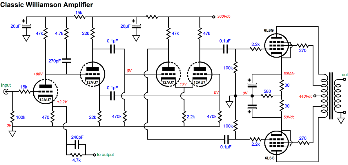
Split Williamson Amplifier
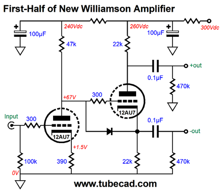
I took the part values and spot voltages from the schematic that appeared in Tremaine's great book, Audio Cyclopedia. (I omitted voltages that I found improbable and I simplified the output tube biasing setup.) The first half of the new two-amplifier design would look like the following.
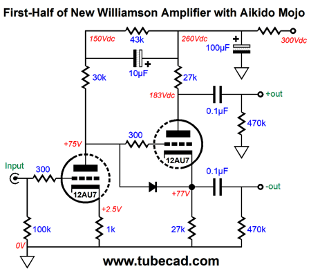
I strove to retain as many of the original parts values as possible. The input triode delivers some signal gain and the split-load phase splitter delivers two phases of output signal, a balanced output signal in other words. We can inject some Aikido mojo by ensuring that both outputs share the same amount of in-phase power-supply noise, which the second amplifier will largely reject, as it will appear as a common-mode signal.
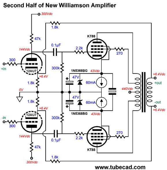
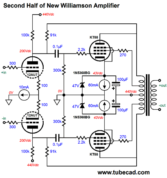
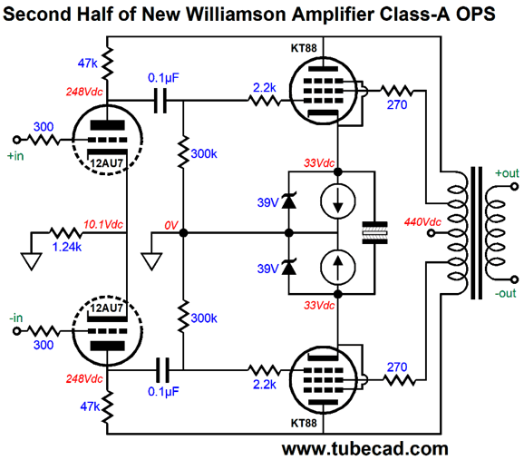
The second amplifier holds a pair of driver triodes and two output pentodes, with two negative feedback loops.
(Fixed-bias could be used instead, which would require the addition of 10-ohm cathode resistors for the output tubes, so the voltage drop across each could be measured.) Note that the secondary is floating, as it makes no direct connection to ground. Also note the 6.4Vdc DC offset at each output terminal. This DC voltage will not harm the loudspeaker, as each speaker terminal sees the same voltage, so no net DC voltage differential exists as far as the speaker is concerned. The biasing of the output tubes is accomplished by the two constant-current sources, which auto bias each output tube individually. Matched output tubes should still be used, however. The 47V zeners provide a maximum cathode-voltage limit. (As the volume goes up, the bypass capacitors tend to become charged up to a higher voltage—until they hit the hard limit set by the zeners.) The non-polarized capacitor that bridges both cathodes helps the output tubes to work as a team. The pentodes are configured in ultra-linear mode. With a pair of KT88 output tubes, we can expect an easy 50W of power output. I just guessed at the 1.8k negative-feedback resistor values. Some actual tweaking of values would no doubt prove essential, but note how we have far fewer variables to contended with here. In fact, my preference would be to keep all the feedback on the primary side of the output transformer.
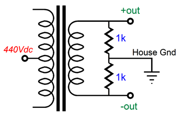
Two feedback loops are used in this partial-feedback variation. See TCJ March 2001 for more details. Note that the output transformer's secondary is left floating. It need not be, as we could ground the bottom terminal; or we could try something far more interesting:
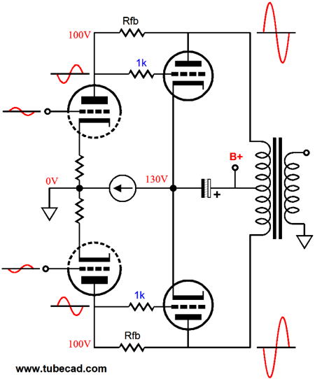
The secondary is now referenced to the house ground, not the signal ground. I have been told by a few speaker-builder types that grounding the speaker driver chassis, frame, metal basket to the house ground improves the sound, resulting in a more relaxed sound. Well, combine that technique with this one and the results might be well worth the effort. If we gave the driver stage 100% of the feedback, we would have what I have called the Ultra-Empathic output stage. See post 305. The "Ultra" portion of the name comes from the placement of the shunting capacitor that terminates into the B+ connection, rather than ground. The "Empathic" half of the name is due to the driver stage knowing what the output stage is doing to the input signal through the plate resistor.
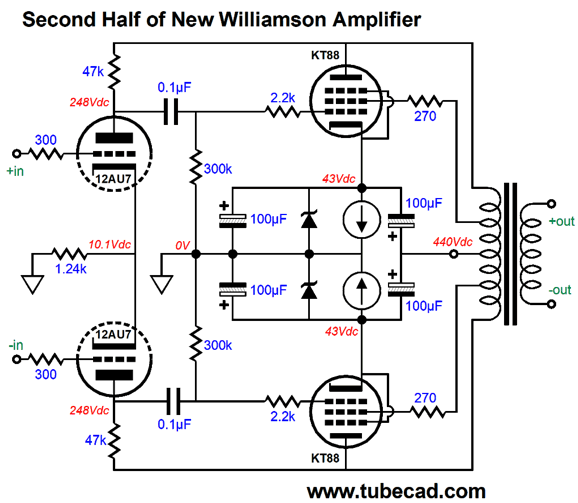
If we decide to leave out the constant-current source for the 12AU7 driver stage, we must take in account the drop in power-supply noise at the 12AU7 plates. In the following schematic, I have chosen part values that result in a 50% power-supply noise division at the 12AU7 plates, which means that the KT88 cathodes must see the same 50% division of power-supply noise.
Each output tube attaches to two 100µF capacitors, which define a 50% AC voltage divider. The bottom 100µF capacitors should be rated for 50V, while the top capacitors should be rated for 500V. Mind you, the differential input stage's common-mode-rejection ratio (CMRR) is poor without the constant-current source, being only about -6dB with the shared cathode resistor. How much negative feedback obtains here? I ran some SPICE simulations and the result was about 6dB. No a lot. We could increase the feedback by triode-connecting the output pentodes. By the way, we could run the output stage in class-A.
Effectively, both constant-current sources work in parallel in AC terms, due to the large-valued non-polarized capacitor that spans both cathodes, but each output tube sets its own DC cathode voltage. But by restricting ourselves to class-A, we end losing about half of the output power. Nonetheless, we would get much better sound as a result. Actually, this a a good time to mention Menno van der Veen's fine book on this topic of feedback from the plate, Trans Tube Amplifiers. He was kind enough to have sent me a copy and to have mentioned me on page 9. Alas, I failed to give it a review back then.
His book is hardcore and not for newbies. For the advanced tube-lover, however, it is a godsend, as its 100 pages are devoted to this subject alone and filled with schematics, graphs, and formulas. The book is much cheaper at www.elektor.com than Amazon.com.
Class-G
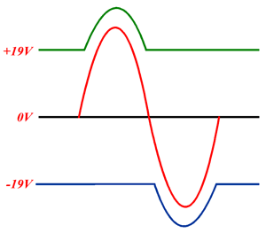
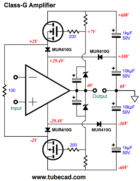
A fair analogy might be a two-speed transmission on a mini-bike, where two gear ratios are available. In the class-G output stage, two power-supply voltages are available. Here is a simple example.
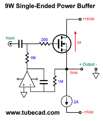
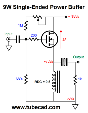
Up to about 40W of output into an 8-ohm speaker, the amplifier runs off the +/-30Vdc power-supply rails. Beyond that power delivery, the MOSFETs all the rail voltages to expand, allowing the amplifier to deliver four times more power. Had class-D amplifier designs not arrived on the scene, no doubt that class-G would be far more popular today. Why? Increased efficiency is one of the big goals in many audio-amplifier applications, such as car audio and self-powered loudspeakers and any application that would be hindered by big, expensive heatsinks. (By the way, at full output, the Class-G amplifier is only slightly more efficient than the typical solid-state class-B amplifier.) In sharp contrast, my interest in class-G finds it focus on something more elusive than increased efficiency—namely, a cheaper way of arriving at better sound. In other words, I strive not for a green amplifier, but a golden-ear amplifier. Let's return to the description of class-G operation. Note, the class-AB or class-B limitation in Slone's definition. Why not class-A output stages. Heck, why not a class-G single-ended power amplifier? As you can imagine, such questions send me off to find my drawing tablet and mechanical pencil. But before we go deep into the weeds of design, let's start slow and simple. The following circuit is a simple power buffer that runs in class-A, single-ended mode.
Very Zen. The single power MOSFET works into a constant-current source load and the DC servo keeps the output centered at 0V at idle. The only thing missing might be some current-limiting circuit to protect the MOSFET in the event of a shorted output. If we added an output coupling capacitor, we would still retain the DC servo to center the output; the added coupling capacitor would, however, offer added safety against a shorted output. If we desire something even simpler, we could replace the constant-current source with an inductor.
Note that this buffer dissipates half the heat that the constant-current source-loaded version did. If the inductor offered no DCR (DC resistance), the output coupling capacitor would not be needed. But as the heavy 2A of idle current will force a voltage drop across even half an ohm of resistance, the coupling capacitor is a good idea. In fact, the DCR proves useful in setting the idle current, as we can measure the voltage drop across it. By the way, 2A of idle current implies an output power of 16W with an 8-ohm load. With an inductive load, the theoretical maximum efficiency of a class-A output stage is 50%; reality, offers less efficiency. For example, the power wasted in the inductor must be subtracted from the potential power output. Moreover, the 15V B+ voltage will not allow the needed 16Vpk voltage swing, so a more realistic power output would be about 12W. Another by the way, the inductor's value need not be nearly as high as you imagine, as the source follower's output impedance is so low. In SPICE simulations, I have used values as low as 10mH with good results. Okay, now that we are mentally warmed up, what would a class-G version of the schematic above look like? And what advantages would result from the move to class-G?
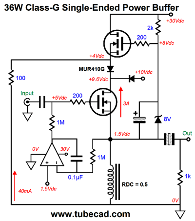
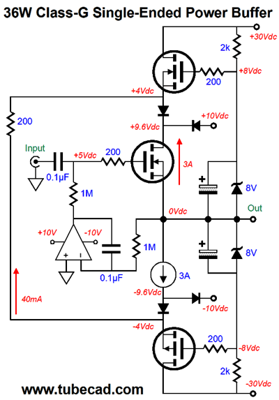
(This design was meant only to serve as a conceptual steppingstone, but dang if it does not look tasty to the ear. This power buffer would put out an insane amount of class-A power. If I were to actually build the beast, I would use a massive heatsink and I would double up—if not triple up—on the top MOSFET, as the single MOSFET will experience about 4Apk of current flow once it is engaged, which is brutal. By using two or three MOSFETs instead, each would see only a fraction of the current. In addition, placing two or three power MOSFETs across the heatsink will result in better heat distribution across the heatsink. I would give each top MOSFET its own 0.22-ohm source resistor to prevent current hogging.) Okay, let's now return to the constant-current source loaded version. How do we create a class-G version? We must apply the class-G technique to both the output MOSFET and the constant-current source.
Note that the top N-channel and P-channel MOSFETs idle at 40mA and each dissipates a tad over 1W at idle. The DC servo's op runs off the +/-10V power-supply rails. But unlike the inductor-loaded version, the maximum theoretical efficiency has dropped to 25%. In other words, this version will need twice the heatsink and twice the power transformer VA rating. Class-A is not for sissies.
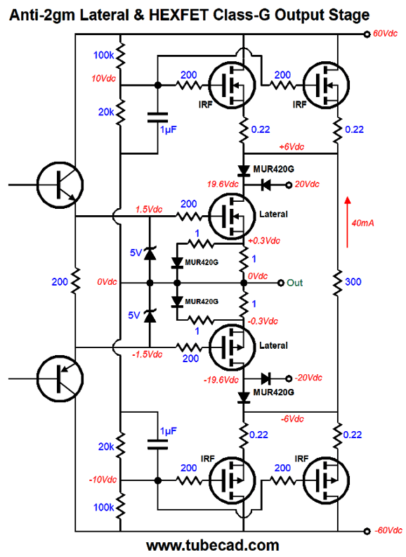
Lateral MOSFET and Class-G
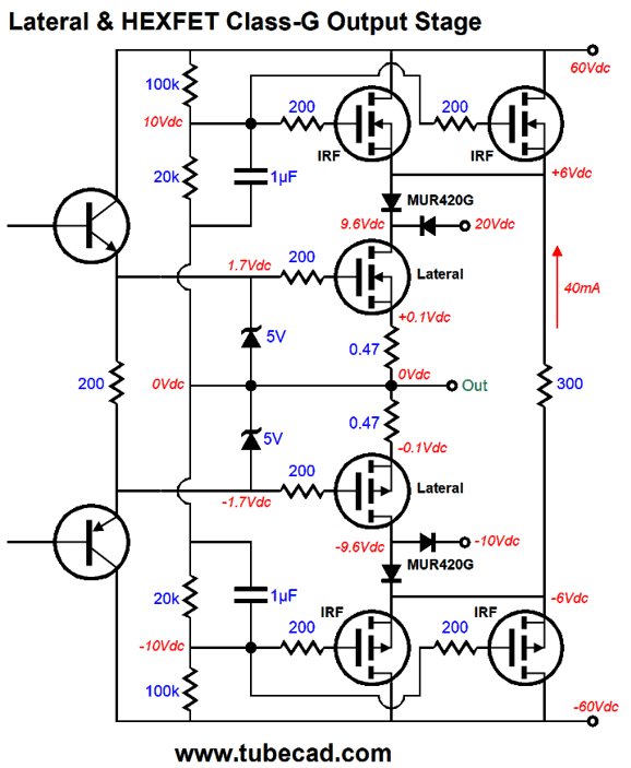
The power-supply-rail voltage are +60V, +20V, -20V, and -60V. The idle current through the lateral MOSFETs is 212mA and only 20mA through each of the HEXFET MOSFETs in cascode. Thus, the laterals will dissipate 2W each and each HEXFET will dissipate 1.08W. In most class-G output stages, the cascode devices are completely cutoff at idle, not here, however, as the 300-ohm resistor that spans across the two cascode sources completes a current path for the outside devices. I discovered the need for this workaround, years ago when I was experimenting with class-G output stages and saw that abrupt turn-on of the outside device resulting in headaches, as the sharp transition from zero current flow to amperes of flow caused burst of oscillations. In addition, a MOSFET's input capacitance is not constant, rising at turn-off. So, by running some current through the outside devices and giving them a simple resistive load at idle, the transition into full engagement goes much more smoothly. The two 5V zener diodes are safety devices that protect the output stage from excessive current flow with shorted outputs, as they limit the maximum source-to-gate voltage. Unlike most class-G output stages, this one does not use zeners to set the engagement voltage for the outer cascode MOSFETs; instead, a two-resistor voltage divider is used. Why the difference? Unlike transistors, MOSFETs do not require heavy current to turn on and I like the idea of an output stage that scales with changes in wall voltage. If the wall voltage runs hot, the transition voltage coming out the voltage divider will scale up; conversely, if the wall voltage sags or the power supply capacitor charges sag under robust demand, the voltage divider will correspondingly drop in turn. By the way, we can get a bit fancier here, as we can strive for a constant-transconductance output stage that sidesteps gm-doubling distortion.
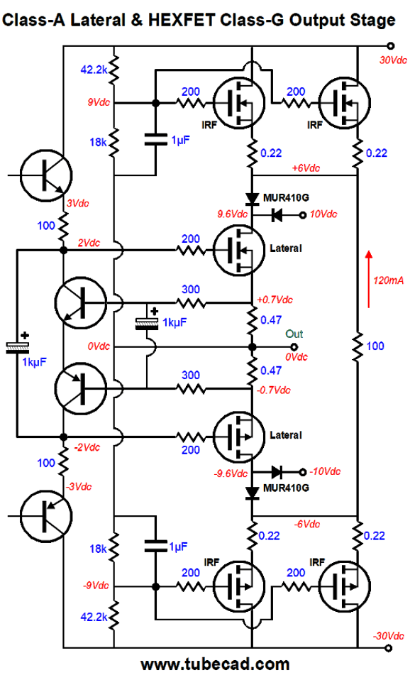
We have increased the idle current flow to 300mA and added two source resistors and two ultra-fast rectifiers (MUR420G). Once the bottom P-channel lateral MOSFET cuts off, the top N-channel lateral MOSFET effectively sees its source resistor halve in value. This will occur about 1.5W of power output into an 8-ohm load. If we doubled the idle current, then we would get 5.7W of output power, class-A power, before switching to class-B. Another approach to a constant-transconductance output stage is to run the lateral MOSFETs in class-A. If neither lateral MOSFET ever cuts off completely we will have a truly constant-transconductance output stage. So what would the idle current be in such an amplifier, such a class-A, push-pull amplifier? Lots is the quick answer. First, we should halve all the power-supply-rail voltages, i.e. +30V, +10V, -10V, and -30V. With these reduced voltages, we should be able to get 36W of output power into an 8-ohm load, which implies a peak current flow of 3A, so the idle current would be half this value, 1.5A. By the way, with the old rail voltages, we could expect something closer to 180W. Both versions require six output devices per channel and both require huge heatsinks and power transformers. Class-A is never cheap.
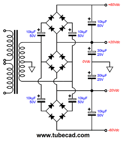
Note the added transistors, which auto-bias the lateral MOSFETs. The 300-ohm resistors and the 1kµF filter away the AC signals. By the way, the power supply needed for a class-G output stage need not require a fancy power transformer, as a single, standard, center-tapped secondary will do.
Note the three bridge rectifiers and the added capacitors, but the typical center-tapped secondary remains. Also note the relatively low capacitor voltages. A 28VAC or 30Vac center-tapped secondary is used. I would use at least a 300VA transformer per channel.
Music Recommendation: Sam Watts' Reflections
//JRB
User Guides for GlassWare Software Since I am still getting e-mail asking how to buy these GlassWare software programs:
For those of you who still have old computers running Windows XP (32-bit) or any other Windows 32-bit OS, I have setup the download availability of my old old standards: Tube CAD, SE Amp CAD, and Audio Gadgets. The downloads are at the GlassWare-Yahoo store and the price is only $9.95 for each program. http://glass-ware.stores.yahoo.net/adsoffromgla.html So many have asked that I had to do it. WARNING: THESE THREE PROGRAMS WILL NOT RUN UNDER VISTA 64-Bit or WINDOWS 7 & 8 or any other 64-bit OS. One day, I do plan on remaking all of these programs into 64-bit versions, but it will be a huge ordeal, as programming requires vast chunks of noise-free time, something very rare with children running about. Ideally, I would love to come out with versions that run on iPads and Android-OS tablets.
//JRB |
Special Thanks to the Special 71!
I am truly stunned and appreciative of their support. In addition I want to thank
All of your support makes a big difference. I would love to arrive at the point where creating my posts was my top priority of the day, not something that I have to steal time from other obligations to do. The more support I get, the higher up these posts move up in deserving attention. Only those who have produced a technical white paper or written an article on electronics know just how much time and effort is required to produce one of my posts, as novel circuits must be created, SPICE simulations must be run, schematics must be drawn, and thousands of words must be written. If you have been reading my posts, you know that my lifetime goal is reaching post 1,000. I have 553 more to go. My second goal is to gather 1,000 patrons. I have 929 patrons to go.
The Tube CAD Journal's first companion program, TCJ Filter Design lets you design a filter or crossover (passive, OpAmp or tube) without having to check out thick textbooks from the library and without having to breakout the scientific calculator. This program's goal is to provide a quick and easy display not only of the frequency response, but also of the resistor and capacitor values for a passive and active filters and crossovers. TCJ Filter Design is easy to use, but not lightweight, holding over 60 different filter topologies and up to four filter alignments: While the program's main concern is active filters, solid-state and tube, it also does passive filters. In fact, it can be used to calculate passive crossovers for use with speakers by entering 8 ohms as the terminating resistance. Click on the image below to see the full screen capture.
Tube crossovers are a major part of this program; both buffered and un-buffered tube based filters along with mono-polar and bipolar power supply topologies are covered. Available on a CD-ROM and a downloadable version (4 Megabytes). |
||


| www.tubecad.com Copyright © 1999-2018 GlassWare All Rights Reserved |