| John Broskie's Guide to Tube Circuit Analysis & Design |
12 June 2013
Restoring Lost Harmonics I am big on restoration, just as I am big on conservation and amelioration (the act of improvement). Surely, if something is worthwhile, then we should strive to conserve it; if something valued has fallen into disrepair, then we should restore it; and if something is disfavored, disobliging, inconvenient, soul-damaging, troublesome, or ugly, then it should be either improved, got rid of, or replaced. (The best philosophical and political systems are those that fit on an index card.) Thus, restoration, the act of getting back, the process of regaining, the attempt at reclamation, recouping, recovery, redemption, repossession, rescue, retrieval, salvage, is usually a noble effort, save for—and once again paradoxically enough—the restoration of the Nobility, the class of persons distinguished by high birth or rank. (No one would want that, right? Or maybe? The modern Olympian impulse and program argues yes, yes, yes!) Artwork, furniture, and our teeth are often in need of restoration, as are classic cars and damaged forests. But what about the world of audio, what needs restoring here? Vintage tube amplifiers and tuners immediately come to mind, as do fine loudspeaker cabinets and turntables. Besides audio equipment, there is the music itself.
In the early days of radio, all broadcasted music was live, as the recording equipment of the day could not compete with sonic glory of live performances. But once audio recordings caught up with live feeds, live music became rare on the radio, as it could not compete with the convenience offered by tape and LPs. In addition, recordings of stellar performances and great artists allowed the timeless to live on and escape the confines of the present. Recorded music, indeed much like music itself, is one of mankind's greatest accomplishments. So what sort of restoration is possible or necessary with recorded music? Great historical recordings are often carefully restored by painstaking adjustments and edits to the master recording. Much like bad plastic surgery, however, sometimes the restoration is worse than the original. But more often, the restoration pleases greatly. (I have found Philips refurbished historical recordings particularly fine.) Unfortunately, such sonic restoring is beyond the average music lover's talent, time, or endurance. What I am about to recommend is something simpler and easier to implement.
But first, here is a quick aside, paradoxically enough (it just one paradox after another today) historians have little problem reading very old newspapers, as they were printed on cotton-based paper (up until the 1890s), which can survive centuries of existence, while still remaining supple and white. But once wood-based paper replaced the finer cotton-rag paper, things changed. Starting in the 1930s, many a historian discovered that a critical newspaper, but not a particularly old one, had begun to return to the sawdust from which it was made. Well, perhaps, we music lovers are in a similar bind.
Not all master tapes survive in pristine shape, as not all tape-coating formulations are equally time resistant. In fact, many master tapes from the 1950s are in better shape than some from the 1960s. In addition, magnetic tape will self-erase, given enough time. Entropy is a steady and tireless worker. With the advent of the perfect sound forever, i.e. the CD and digital recordings, a new problem arose: perfectly limited musical information forever. A digital recording's sampling rate sets a strict high-frequency limit that is quite unlike the limited high-frequency bandwidth of analog recordings, which gently fall off at high frequencies, unlike the digital cliff edge, after which high-frequency recording abruptly stops; period. Is the digital truncation of high frequencies a big deal? We are after all men and not bats, so cares if the recording's high-frequency response is severely and brutally shaved off? Well, it is always worth remembering that in nature there are no brick-wall filters. My guess is that if the CD's high-frequency response had extended out to 30kHz, few would mind. Why? I remember reading of a simple but powerful experiment performed in England back about fifty years ago, wherein a high-quality recording that extended out to 40kHz was passed through an adjustable low-pass filter. The result was that, for listeners not to notice the filter's presence, the high-frequency -3dB down frequency had to be over 27kHz or so, something a CD's 44.1 kHz sampling rate cannot allow, as it imposes a strict limit of 22kHz. As the Wiki puts it:
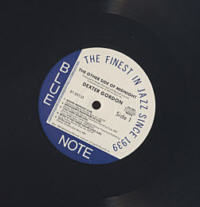
I remember a vivid sonic demonstration that John Atwood made for me at his home. First, John played a fine LP on his equally fine turntable. This was the absolute sound, as this was the signal source. The LP's actual recorded performance was not in the least important, as the sonic buck stopped at the LP playback. The LP might have held ticks and pops and a little wrap, or it might have received heavy sonic manipulation at the hands of an overzealous recording engineer, but the signal out of the phono stage was the target and the digital recordings made of this signal had to hit this target. How close did they come? I was quite impressed, as the high-resolution digital recordings came close to the LP's (absolute) sound; I would say that it was about 95% on the mark. At one point, John asked if I would like to hear a standard CD-quality recording of the LP. I was keen to do so, as I wondered if I would hear a substantial difference.
Bleak and grim was the result, amazingly so. Gone were the shimmer and luster; even the ticks and pops sounded flat and distant. "Bereft of life" was how I described the sound. I realized instantly what a bad trade we had made by accepting lifeless sound in exchange for losing the LP's pops and ticks and inconvenience. Although to be frank, it wasn't as if we had swapped the finest vellum or parchment paper for coarse, splinter-filled wood-pulp paper, as the most LPs made in the in the 1970s were poorly and cheaply made, so the thick, flat, high-quality LPs of the 1950s were a distant memory. (Speaking of splinters, I remember buying LPs back in the 1970s that held vestiges of recycled LP's label floating in the black vinyl and almost all LPs held a fat thumb indent due to being pulled from the record press too soon, before the LP had completely hardened.) Thus, the CD fought an easy fight against a tired and injured opponent. Now here is the problem: many of us own hundreds, if not thousands of CDs, which we are not willing (or unable) to replace with high-resolution downloads. What can we do? One thought that comes to mind is a harmonic restoring circuit that would add some of the missing ultra-sonic information to CD playback. Such a circuit would purposely add harmonic distortion. For example, the second harmonic of 12kHz is 24kHz. Why do I think that such a setup would work, rather than just muddy the sonic presentation?
The answer is that I have repeatedly experienced the odd situation wherein an LP sounded much better than the CD, although both were based not on an analog master tape, but on the same digital recording! Surely, the CD should have easily won this shootout, but it didn't. Why not? My best guess is that the LP, because it, like the phono cartridge and tonearm and turntable, is a mechanical device, being subject to vibrations and the resulting resonances, resonances which helped restore some of the missing harmonics lost in the original highs-truncated digital recording, thus reestablishing a more natural tonal balance.
The hope is that the above sonic image could be transformed into the following image. (Some might argue that both pictures are flawed, as the first is washed out, while the second is over saturated. Possibly, but I know which I prefer.)
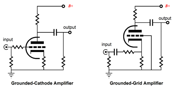
What we need is a tube-based circuit that offers a fair amount of harmonic distortion and no voltage gain and, preferably, no phase inversion. In addition, it should add no hum or other sonic blight. A simple grounded-cathode amplifier might immediately come to mind, but such a circuit will invert the phase and produce voltage gain and present a relatively high output impedance; more importantly, it may not produce enough harmonic distortion. How much harmonic distortion is enough? My design goal was 1%, which I chose quite arbitrarily; perhaps much more is needed.
Designing A Harmonic Restorer
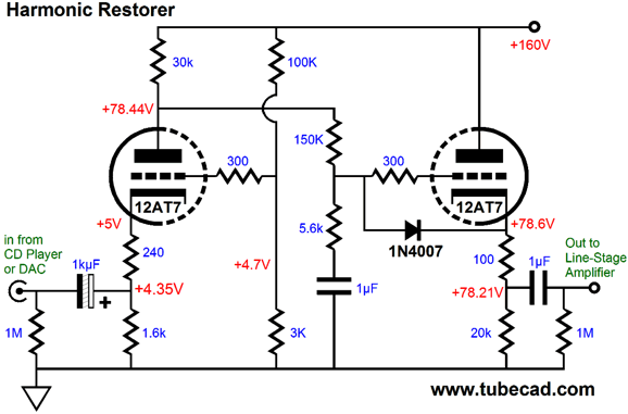
One huge advantage the grounded-grid amplifier offers is that the grid, which is usually grounded, can be used as an inverting input. This added inverting input allows us use to use an Aikido noise-reduction technique to vastly improve its PSRR. And the usual disadvantage the grounded-grid amplifier, its low input impedance, is not a problem in this application, as the CD or DAC's output will directly couple to the input and not pass through any volume potentiometer. We still face the problems of voltage gain, a high Zo, and not enough distortion, but there is a workaround. We can burn off excess gain with simple two-resistor voltage divider. We can produce higher distortion by letting the grounded-cathode amplifier swing large plate swings. We can greatly enhance the circuit's PSRR by using a two-resistor voltage divider to feed the grid a sampling of the power-supply noise, which will null the power-supply noise at the plate (the circuit's output).
And, finally, we can use a cathode follower to offer a low output impedance.
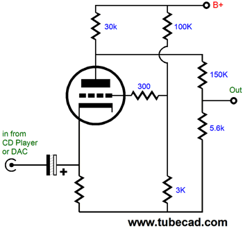
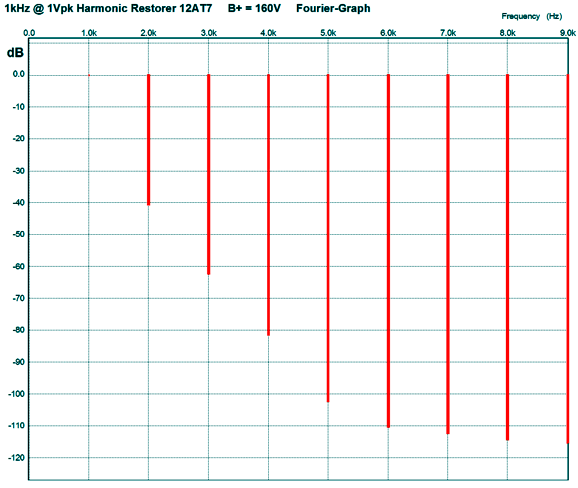
The above schematic shows my complete Harmonic Restorer circuit. Of course, different tubes, different part values, different operating voltages, and even different topologies could be used. The key feature is that a lot of voltage gain was applied to the CD's output signal and the extra gain was then reduced to unity by the two-resistor voltage divider. The 240-ohm cathode resistor was added to limit the input tube's distortion to 1% at the circuit's output. The 1N4007 rectifier was added to protect the cathode follower at startup, when the triodes are cold and not conducting; without this added diode, the cathode follower's grid would see the full B+ voltage while its cathode would be at ground potential; not good. The 1µF capacitor that terminates the 150k and 5.6k voltage divider is there to ensure that this voltage divider only divides AC signals, not DC voltages. The cathode follower's 100-ohm cathode resistor is there to buffer the cathode follower's cathode from external capacitive loads; not good. The 1kµF input capacitor might not be necessary, as many CD players already hold a large-valued electrolytic coupling capacitor at their outputs, which might be oriented with the positive end at the output. If I were to build this circuit today, I would certainly use a Panasonic non-polarized electrolytic coupling capacitor at the input, as they sound quite good. The B+ voltage is a tad anemic, but I had mind a DC-to-DC converter that would run off an external 12Vdc power supply, which would heat the heaters. In other words, I imagined housing the Harmonic Restorer circuit in a cute little extruded project box, with a wallwart providing the needed juice. Of course, a much fancier power supply could be used. In SPICE simulations, the above circuit worked quite well, as the following Fourier graph shows. The second harmonic comes in at 1%, which might prove too clean to restore the CD's sonic luster. I remember reading how it took over 5% of second harmonic distortion for most listeners to notice its presence. Nonetheless, the remaining harmonics fall off an beautifully single-ended fashion.
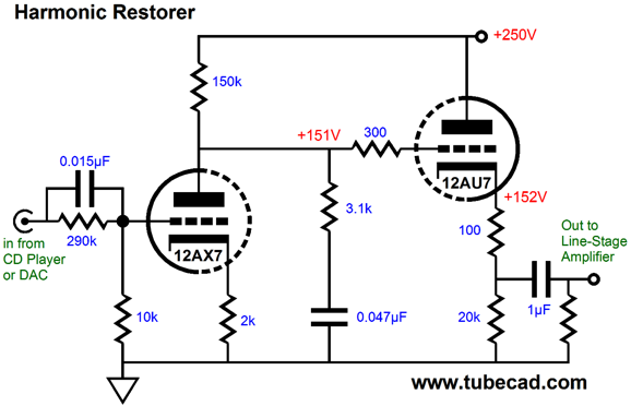
Frequency-Selective Harmonic Restoration Given an extra ten minutes, I can come up with an additional ten variations on the Harmonic Restorer circuit. For example, how about adding some negative or positive crossfeed, which would narrow or widen the sound stage? Or how about two potentiometers, one at the input and one in the middle, so an adjustable amount of harmonic distortion could added? Or we could place a frequency-selective shelving network in front of the Harmonic Restorer circuit and a counter shelving network in the middle of the circuit. Why? This approach would produce very little distortion at frequencies below the shelving frequency and more distortion above it. A frequency selective Harmonic Restorer, in other words. The following is one possible implementation.
The tube used is a 12DW7, which is a dissimilar tube that holds a 12AX7 triode and a 12AU7 triode. The input shelving network freely passes the high frequencies, but greatly attenuates the lower frequencies, as the 290k and 10k resistors define a severe two-resistor voltage divider. The input triode's output impedance at its plate is in series with the second shelving network made up of the 3.1k resistor and 47nF capacitor. This second shelving network will undo the first network's frequency skewing. So, the highs end up getting amplified and then attenuated, causing the high frequencies to hold more harmonic distortion. What is missing is a PSRR-enhancing technique and the protection diode for the cathode follower
Next Time
//JRB
|
I know that some readers wish to avoid Patreon, so here is a PayPal button instead. Thanks.
John Broskie
And
High-quality, double-sided, extra thick, 2-oz traces, plated-through holes, dual sets of resistor pads and pads for two coupling capacitors. Stereo and mono, octal and 9-pin printed circuit boards available.
Designed by John Broskie & Made in USA Aikido PCBs for as little as $24 http://glass-ware.stores.yahoo.net/
The Tube CAD Journal's first companion program, TCJ Filter Design lets you design a filter or crossover (passive, OpAmp or tube) without having to check out thick textbooks from the library and without having to breakout the scientific calculator. This program's goal is to provide a quick and easy display not only of the frequency response, but also of the resistor and capacitor values for a passive and active filters and crossovers. TCJ Filter Design is easy to use, but not lightweight, holding over 60 different filter topologies and up to four filter alignments: While the program's main concern is active filters, solid-state and tube, it also does passive filters. In fact, it can be used to calculate passive crossovers for use with speakers by entering 8 ohms as the terminating resistance. Click on the image below to see the full screen capture.
Tube crossovers are a major part of this program; both buffered and un-buffered tube based filters along with mono-polar and bipolar power supply topologies are covered. Available on a CD-ROM and a downloadable version (4 Megabytes). |
|||


 vs
vs 


| www.tubecad.com Copyright © 1999-2013 GlassWare All Rights Reserved |