| John Broskie's Guide to Tube Circuit Analysis & Design |
26 Aug 2008
One More Phono Preamp Design
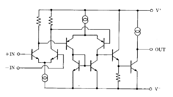
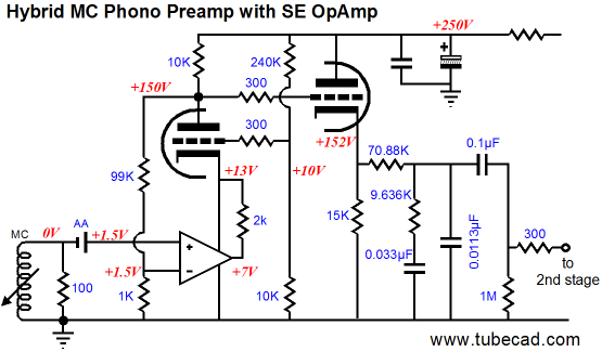
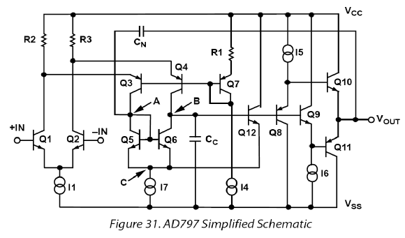
The low-noise OpAmp derives its power from the same high-voltage power supply that the vacuum tubes do, which greatly simplifies the power supply design and construction (and allows for using only tube rectifiers). The OpAmp’s negative input receives the input signal from the cartridge and the battery presents a 1.5V DC offset to the OpAmp, which permits the OpAmp to function, as its inputs must be at some DC voltage higher than its negative power supply connection—in this case, ground. The triode that sits above the OpAmp shields the OpAmp from the high-voltage B+ and works as a cascode element. In other words, the OpAmp does all the amplifying, using the triode as a relay device that allows the OpAmp’s current to pass freely into the plate resistor above it. This means that the tube plays a secondary role, which the addition of the feedback loop makes even less primary. The 99k feedback resistor attaches at the triode’s plate and returns a portion of the signal present at the plate to the OpAmp’s positive input. No, the schematic is not drawn incorrectly. The configuration of the OpAmp and its 2k load resistor makes the cascode circuit an inverting circuit, so the OpAmp’s inputs must be inverted as well. The battery’s 1.5V DC offset must be matched at the OpAmp’s positive input, which forces the plate to sit at 150Vdc. The plate resistor thus sees a 100V differential, which implies a 10mA current draw, all of which must flow into the OpAmp’s positive power supply pin, except that the feedback resistor pair will see current flow of 1.5mA, so the OpAmp need only source 8.5mA. Now a typical low-noise OpAmp draws a quiescent current of around 3.5mA, so the additional 5mA must flow through the 2k load resistor, bringing the total to the required 10mA. (If the OpAmp had drawn only 1.5mA, the load resistor’s value would have to be closer to 1,400 ohms.) Note that the 5mA that flows through the load resistor sets the peak positive-going voltage swing for the triode’s plate, as the subtraction of the 5mA from the plate resistor’s idle current of 10mA yields a positive-going voltage swing of +50V (the feedback resistors will drag the actual positive voltage down to 45V). The peak negative voltage swing must be less, as the OpAmp’s output cannot swing as much positively as it can negatively (here the feedback resistor pair helps, not hinders, the negative swing). Nonetheless, the phono stage does not require huge voltage swings, as the cascode circuit’s gain of 100 against the MC cartridge’s wimpy output is still a miniscule amount of voltage swing. One aspect of this hybrid cascode circuit that tickles me is the pure single-ended mode it runs in spite of the OpAmp holding a push-pull output stage. How is that possible? At idle, the OpAmp must deliver a steady 5mA of current into its 2k load resistor, which means that its output stage’s bottom output device is completely turned off and that its top output device sees the full 5mA of current flow through it. (The load resistor works much like the single ended pull-down resistors used with OpAmps and bipolar power supplies. See Solid-State Variation and Amplifier Class-XD™) A second ticklish feature is the hybrid circuit’s making use of the best features from the two technologies: super-low noise and microphonics from the solid-state OpAmp and huge, clean voltage swings from the vacuum tube. The hybrid cascode circuit provides +40dB of low-noise, low-output-impedance gain that then drives the cathode follower’s grid. Since the cathode follower adds no gain, why not include its output in the feedback loop? In other words, why not terminate the feedback resistor into the cathode follower’s cathode? Such an arrangement is certainly possible and it would definitely lower the distortion and noise at the cathode follower’s output, but my hope was to pass the signal to vacuum-state device as soon as possible. After the cathode follower, a simple passive RIAA equalization network and all-tube second gain stage complete the phono stage. The 12AX7-based second stage furnishes us with an additional +34dB following gain, bringing the total after equalization to +54dB; this will be too low for some MC cartridges, but enough for most. A few caveats: first, dual and quad OpAmps cannot be used; only single OpAmps. The cascode trick only works because all the current flowing through the OpAmp’s output stage must also flow in and out of the OpAmp’s power supply pins. If two internal OpAmps share the same two power supply pins, then the sum of both OpAmps' current conduction will flow in and out of the two power supply pins, mixing the two OpAmps’ signal current together. Second, a good understanding of the OpAmp’s internal schematic is essential. For example, the exemplary NJM2122* is an ultra-low-noise, dual operational amplifier, with a major difference. It runs a pure, honest-to-God, single-ended output stage, not the typical push-pull stage. So it gets its first strike from being a dual OpAmp and its second strike from its using a constant-current source in its output stage. Because the constant-current source sits between the OpAmp’s positive power supply pin and its output pin, the plate resistor will never see the current variations through the load resistor. Below is the NJM2122’s schematic, which should help make this more obvious.
In other words, we do not want a constant-current to flow into the triode’s cathode, which the OpAmp’s constant-current source ensures. The workaround for such a topology is to place the load across positive power supply connection and the OpAmp’s output, as shown below.
On the other hand, 99.9% of single OpAmps use a topology similar to the following, wherein a push-pull output stage is used. The input stages differ far more than the output stages do.
Next Time
//JRB
*Thanks to Andy Bartha for tipping me off about this amazing OpAmp.
|
Only $9.95
The Tube CAD Journal's first companion program, TCJ Filter Design lets you design a filter or crossover (passive, OpAmp or tube) without having to check out thick textbooks from the library and without having to breakout the scientific calculator. This program's goal is to provide a quick and easy display not only of the frequency response, but also of the resistor and capacitor values for a passive and active filters and crossovers. TCJ Filter Design is easy to use, but not lightweight, holding over 60 different filter topologies and up to four filter alignments: While the program’s main concern is active filters, solid-state and tube, it also does passive filters. In fact, it can be used to calculate passive crossovers for use with speakers by entering 8 ohms as the terminating resistance. Click on the image below to see the full screen capture.
Tube crossovers are a major part of this program; both buffered and un-buffered tube based filters along with mono-polar and bipolar power supply topologies are covered. Available on a CD-ROM and a downloadable version (4 Megabytes). Download or CD ROM E-Mails from two happy customers:
High-quality, double-sided, extra thick, 2-oz traces, plated-through holes, dual sets of resistor pads and pads for two coupling capacitors. Stereo and mono, octal and 9-pin printed circuit boards available.
Designed by John Broskie & Made in USA Aikido PCBs for as little as $24 http://glass-ware.stores.yahoo.net/
|
|||


| www.tubecad.com Copyright © 1999-2008 GlassWare All Rights Reserved |