| John Broskie's Guide to Tube Circuit Analysis & Design |
| 18 May 2014
Single-Ended Circlotrons
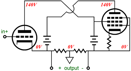
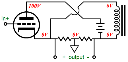
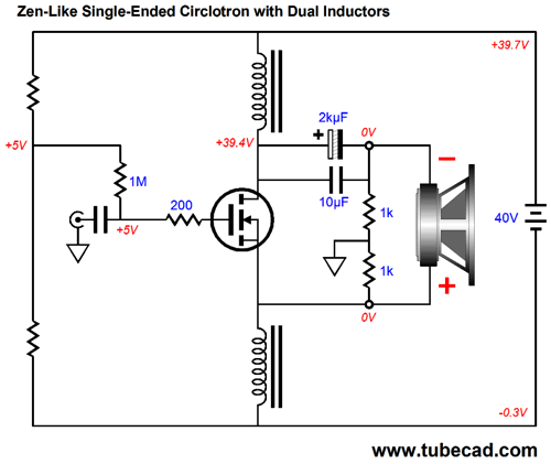
Do not be fooled into believing that the above single-ended Circlotron circuit somehow sneaks in a balanced signal to the drive the pentode, thereby creating push-pull operation, as nothing like that happens, which can be shown by replacing the pentode with either a constant-current source or an inductor, as shown below.
We assume a perfect inductor here, which displaces zero DC voltage, as it presents zero DC resistance. Thus, a single floating power supply is all that is needed. In spite of it receiving an unbalanced input signal, it puts out a balanced output. Indeed, it is not a convoluted cathode follower, as it puts out voltage gain. Much in the same way that the split-load phase splitter also puts out gain, if the differential outputs are summed, which they should be. This makes sense, as this phase splitter and the Circlotron are brothers—if not fraternal twins. In other words, not all Circlotrons need to be arranged horizontally, as we can use the vertical arrangement instead.
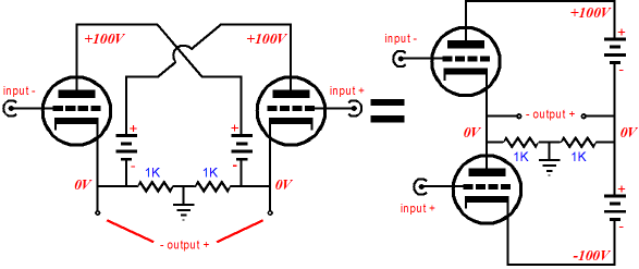
In the vertical Circlotron on the right, either the top or the bottom triode could be replaced by a constant-current source (CCS), which would create a single-ended Circlotron. Where the ground , the circuit's voltage and signal reference is placed makes all the difference in the world. If the ground attaches to a triode's cathode, the triode functions as a grounded-cathode amplifier; if at its plate, a cathode follower; and if at its grid, a grounded-grid amplifier. We place ground where we choose. If we place it at a 9v battery's negative terminal, we have +9-volt power source; if we place it at is positive terminal, a -9-volt power source. If we cut the battery's case open and attach the ground to the junction between the first three 1.5V battery cells and the next three cells, we create a bipolar ±4.5V power supply. The key, essential, fundamental all-defining aspect of the Circlotron is that the ground appears mid load. That's it. Period. If the ground is placed at either end of the load, the amplifier is no longer a Circlotron; if placed at the middle of the load, then it is, no matter how much it doesn't look like the conventional Circlotron circuit, a Circlotron design. The name "Circlotron" was perhaps a brilliant marketing decision, capturing a space-age flavor, but it was quite useless in explicating the circuits essential quality. I have been told that I am wrong here, that the name "Circlotron" was inspired, as it perfectly described the amplifier's key attribute, i.e. it completed a circle, a circle of current. Okay, I hope you didn't spill your coffee. ALL CIRCUITS COMPLETE A CIRCLE OF CURRENT, which is why we call them "circuits." A far more informative name for this amplifier would have been "split-load amplifier," in spite of the gnashing of teeth from the marketing department. As mentioned earlier, a spilt-load phase splitter can become a Circlotron, if a single load is thrown across its two outputs.
The load is split by both the two 1M resistors and, far more significantly, by the two 5k resistors. The output impedance is low, but not as low as a cathode follower's, but far lower than a grounded-cathode amplifier's.
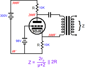
Note how this Circlotron's output impedance is twice that of the push-pull variety, i.e. Zo = rp/(µ + 1), which makes sense, as the push-pull version effectively double the transconductance over the class-A overlap region. The following circuit is a Circlotron, although only few would recognize it as being so. The key feature is that the ground was placed mid load. Mind you, the external load will be attached to the transformer secondary, but the reflected impedance is halved at the center tap on the primary, thus making a midpoint ground attachment to the load; thereby making the the Circlotron label correctly apply to the circuit.
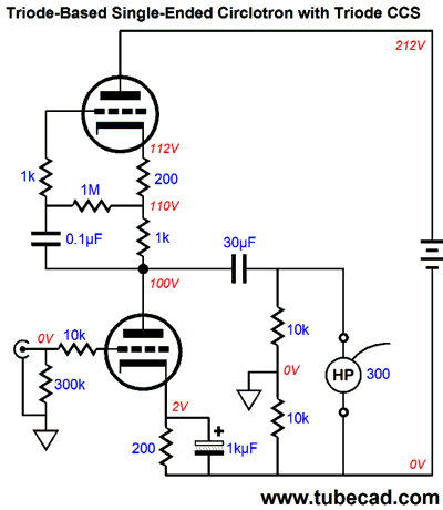
Note this not a cathode follower circuit, nor is it a grounded-cathode amplifier; it is a Circlotron. It produces signal gain; not much, being a always a bit less than 2, but gain nonetheless across the primary. Note that the 20V voltage drop across the primary is the result of its DCR (DC resistance) against the idle current flow. So, in effect, the primary becomes part of the cathode biasing scheme. The power supply is floating and will move about as the signal prompts it to move up and down. One key consideration is that an air-gapped output transformer must be used (i.e. a single-ended design), as the primary we see a sustained DC current flow. On the other hand, we can place the transformer at the plate.
This, too, is a Circlotron; it is not a grounded-cathode amplifier; its gain across the primary will equal a little less than 2. Note how the ground attaches at the center tap and its power supply is floating. Also note how the cathode sits at -330V. Or, how about a para-feed arrangement, wherein the primary is in parallel with the triode? Is that possible? Sure.
The inductor functions as a constant-current source of sorts and allows the plate to swing up to voltages far in excess of the B+ voltage. The great advantage to this circuit is the improved PSRR, as the choke will shield the triode and the primary from much power-supply noise. An added advantage is that a push-pull output transformer can be used (i.e. no air gap), as the primary never sees a sustained DC current flow. Or, if you dislike chokes, we could replace the choke with a power pentode, as shown below.
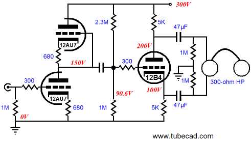
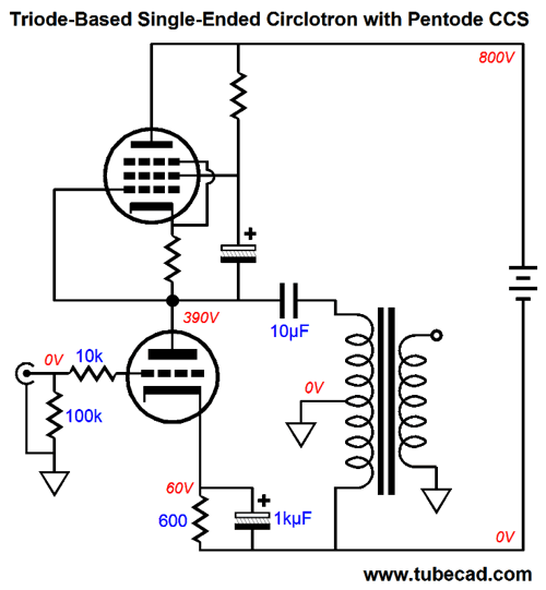
Just imagine a monobloc chassis that held one output transformer, one 300B, and one KT88 (or KT120). Note how the B+ voltage is now a scary 800V. Like the previous design, this single-ended Circlotron amplifier will exhibit a fine PSRR. Of course, we can forgo the use of an output transformer, driving the load directly, if the load impedance is high enough; for example, a 300-ohm headphone, such as the famous Sennheiser HD650 or HD800.
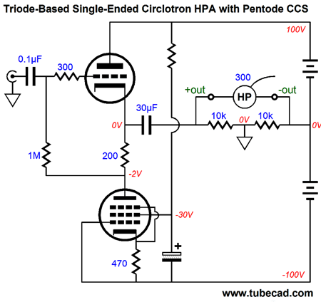
The pentode functions as a constant-current source and the power supply floats. Why use the 30µF coupling capacitor, if 0V obtains on both side of the outputs? The headphones are expensive and if a tube fails or is giggled in its socket, thereby losing contact, a huge voltage swing could damage a headphone driver. Never a good outcome. The coupling capacitor is a safety feature. On the other hand, if an output transformer is used, say to drive 50-ohm headphones, then the capacitor could be eliminated. A somewhat sneaky trick is to eliminate the single coupling capacitor by using two instead. I have discovered that 99% of audiophiles cannot see two coupling capacitors, although they can readily see one.
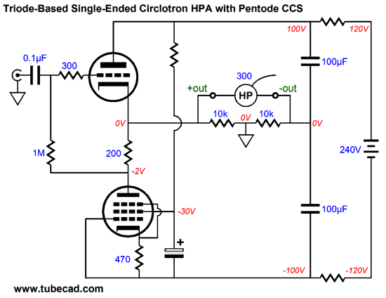
How many coupling capacitors do you see attaching to the headphone? None, one, or two? I see two, the two 100µF capacitors, which prevent a DC flow of current into the headphone driver and which couple the driver to the rest of the circuit in AC terms. At the same time, these two coupling capacitors work as power-supply filtering capacitors, smoothing away ripple, improving PSRR—always a worthy goal in a headphone amplifier.
Zen Power Amplifier
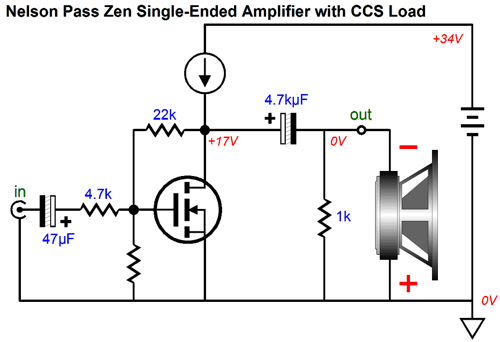
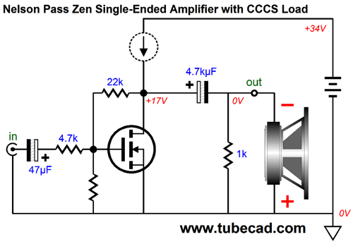
Where the 6AS7 manages to summon a mere 7mA change in current conduction in the face of a 1V change in its grid voltage, the IRFP240 power MOSFET achieves a change of 11A of current conduction. Divide 11 by 0.007 to see how truly great the difference is. If you have only worked with tubes, such a staggering amount of transconductance is likely to do to you just that: stagger. But for those who work exclusively with solid-state power amplifiers, the 11A/V amount of transconductance seems a paltry amount. For example, if a solid-state power amplifier boasts of a dampening factor of 1,000, then its effective transconductance is 125A/V. In other words, Pass had to skillfully use the relatively little amount of transconductance he had available to him. Do not forget that his single output device had to provide three essential attributes: voltage gain, low distortion, and a low output impedance. If his Zen amplifier put out more voltage gain, then both distortion and output impedance would rise. If it put out a lower output impedance, then gain would fall along with distortion. Another design problem Pass faced was dealing with the power MOSFET's high input capacitance. Where the 6AS7 presents an input capacitance of 6.5 pF, the IRFP240 presents a whopping 1250 pF of capacitance. The MOSFET's high input capacitance forced Pass to use relatively low-valued input and feedback resistors, which resulted in a relatively low input impedance for the ZEN amplifier, certainly far lower than what tube folk were used to driving. And let no one belittle Mr. Pass's accomplishment in the Zen amplifier, as in the words of Paul Valéry: “Everything simple is false. Everything complex is unusable.” Making a simple, true, and usable power amplifier is far more difficult than making a complex one. Below, we see Pass's Zen amplifier fleshed out.
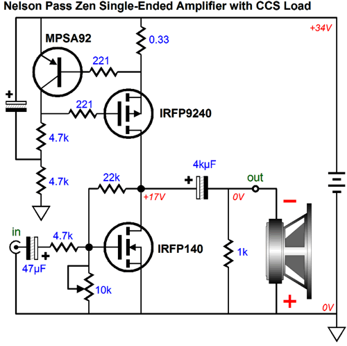
The IRFP9240 is a P-channel power MOSFET, which is configured as a constant-current source in the Zen amplifier. The PNP transistor, the MPSA92, monitors the voltage drop across the 0.33-ohm source resistor. If this voltage exceeds its base-to-emitter voltage, it conducts more current, which forces the IRFP9240's gate more positive, thereby reducing the MOSFET's current conduction and the voltage drop across the resistor. If voltage drop across the resistor falls short of the transistor's base-to-emitter voltage, the transistor conducts less current, which forces the IRFP9240's gate to become more negative relative to its source, forcing the MOSFET's current conduction up along with the voltage drop across the resistor. The 4.7k input resistor and 22k feedback resistors set the voltage gain for the Zen amplifier. The 10k potentiometer sets the centering of the output stage at half the B+ voltage. The input and output coupling capacitors seal off the DC voltage within the Zen amplifier. The loudspeaker is shown in an inverted attachment to the amplifier's output, with is negative terminal attaching to the amplifier's output, which undoes the amplifier's phase inversion at its output. That is the Zen amplifier in a nutshell. And as Vladimir Nabokov so nicely put it in his novel, Laughter in the Dark, "...although there is plenty of space on a gravestone to contain, bound in moss, the abridged version of a man's life, detail is always welcome." For example, the electrolytic capacitor that couples the B+ to the junction of the two 4.7k resistors works to improve the PSRR of the constant-current source (CCS). And we could go on and on, but let's move on to a radical variation on the Zen, as shown below.
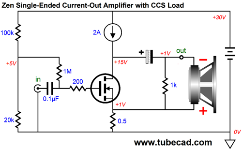
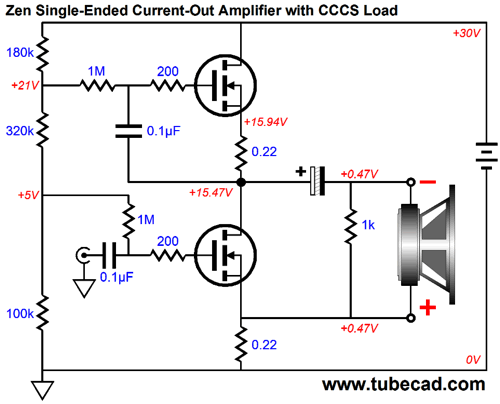
Radical indeed. Many audiophiles believe that using a different brand of coupling capacitor or tube marks a radical departure, but this an altogether truer radical change—an extreme departure from the usual or customary, a truly fundamental change. This power amplifier no longer puts out a measured output voltage that directly relates to its input voltage, but a measured output current. In other words, this is a current-output power amplifier, not a voltage amplifier. The output current is fixed, not the output voltage. Thus, a 4-ohm, load will prompt only half the voltage swing that an 8-ohm load would. At the same time, based on the input signal, an identical amount of current will flow, even if the loudspeaker is a 1-ohm or 16-ohm design. Because the speaker terminates into the MOSFET's source, not ground, the output signal is a balanced one that is not ground referenced. In addition, a small, identical DC voltage is present at both speaker terminals, so no damage occurs to the speaker, but a small spark could fly if a speaker lead accidentally shorted to the chassis. Where is the negative feedback loop? It's there, but so simple that it is hard to see, the 0.5-ohm source resistor. This resistor supplies the MOSFET with degenerative negative feedback that MOSFET's current variation from straying too far off course.
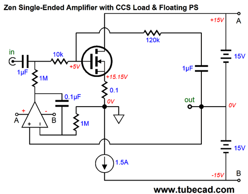
The power MOSFET now rests above the constant-current source and the power supply is no longer grounded, but floats about with the output signal. The large-valued electrolytic coupling capacitor is gone and the DC offset is managed by an OpAmp-based DC servo loop. This variation still inverts the phase at its output and delivers comparable performance to the original Zen amplifier. But there are important differences. For example, the inclusion of the DC servo not only eliminates DC offset voltages, it auto-biases the output MOSFET. In addition, because the power supply floats, each channel must get its own floating power supply. This is no big deal in a monobloc power amplifier, but it makes building a stereo power amplifier a tad more difficult. Moreover, the OpAmp attaches to the floating power supply and its output follows the power amplifier's output signal, so a dual OpAmp cannot be shared between channels.
Much like a sailor who has lost his compass, many get disoriented when it comes to floating power supplies, wishing the damn thing could be grounded—the way that all proper power supplies should be. Well, for these troubled individuals, here is a compromise circuit.
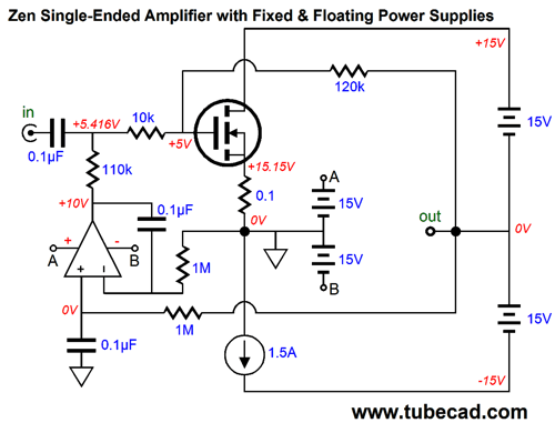
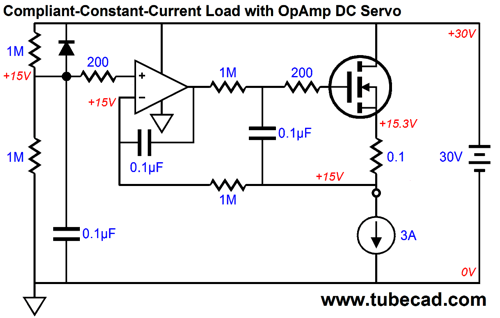
With the addition of the conventional, fixed, ground–referenced ±15V power supply, dual OpAmp can now be shared between channels, although each channel will still require its own floating power supply of the output MOSFET and its constant-current source. In addition, we jettisoned the 1µF coupling capacitor that connected the 120K feedback resistor to the output. The OpAmp's output no longer follows the power amplifier's output, but puts out a steady DC voltage, varying only with the need to erase any DC offset from the output.
Circlotron Meets Zen Well, what happens if we place the ground midpoint on output load in the above Zen amplifier circuit? We get this:
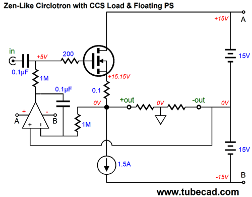
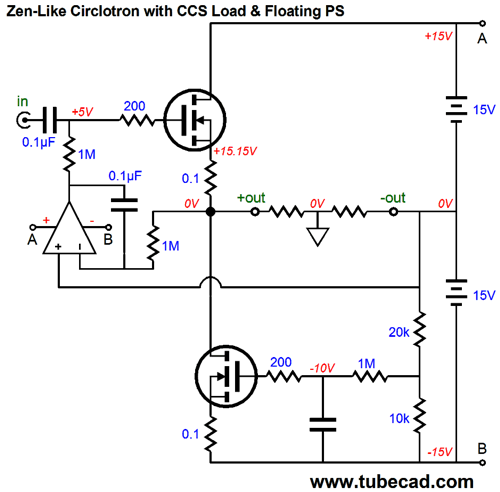
The power supply is referenced to the output and no longer grounded. The ground is located midpoint of the load. The amplifier is still an amplifier, as it produces voltage gain, albeit not much, a maximum of 2, or +6dB. Nonetheless, it is not a unity-gain buffer, although its output impedance is fairly low. It is a Circlotron, a Zen Circlotron, as the single power MOSFET does all the work, all the creation of voltage gain ad reduction of distortion and providing a low output impedance. The constant-current source could be replaced by a choke and the bottom 15V power supply eliminated (if the choke's DCR is sufficiently low). More likely, we would use another power MOSFET in a CCS configuration, such as this.
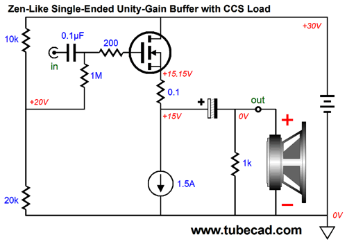
This Zen Circlotron will require a large input signal, due to its low gain of 2. But is tubes are good at anything at all, they are good a swinging voltage. In other words, a robust tube-based line-stage amplifier could easily drive this amplifier to full output. (Think Aikido.) Of course, some might argue that we shouldn't bother with the Circlotron topology at all, if we are going to use a hot tube-based line-stage amplifier to provide the voltage gain; we could use a power buffer design instead, such as the one shown below.
The power MOSFET functions as a source follower, which delivers near unity gain, low distortion, and a low output impedance. With a bipolar power supply, the large-valued coupling capacitor could be eliminated at the output. Certainly, no one size fits all, so perhaps they are right. Still, my goals are more theoretical than practical. I am exploring what is possible, not necessarily what is easiest or, even, preferable.
CCCS ???? As behooved an electrical engineer, he had done his math and he had discovered that there were only 676 possible two-letter acronyms and 17576 possible three-letter acronyms, which seemed comfortably larger, but not really. He pointed out that many, such as ZZZ, would find no takers, so the effective number of possibilities was much smaller. (Apparently he had never heard of the Zaire Zootomy Zoolatry or the famous Zurich Zen Zeitgeist or the Zeeland Zephyr Zeppelineers or the...) His proposed remedy was that the federal government should establish a special department that would govern and award acronyms, much as the patent office issued patents. I told him that I had the perfect name for the new governmental agency: the Acronym Selector Service, which he truly seemed to like, until he worked out its acronym. (Indeed, everyone knows that acronym would conflict with the already established acronym for Application Support Specialist.) Well, that is my introduction to what I am regretfully about to do, which is to give you another dang electronic acronym to remember: CCCS. It stands for Compliant-Constant-Current Source, which is a circuit function that I have used many times over the past four decades, but which seems to have no name. The word "compliant" says it all, for it means a willingness or disposition to comply, and suitable synonyms are acquiescent, adaptable, adjustable, complacent, malleable, moldable, pliant, shapeable. The idea is this: often we need a circuit that mimics a constant-current source in that it must present a very high output impedance, but which does not establish a fixed current; rather, it strives to maintain whatever current flow enters it. But if the current flow slowly varies, it will also slowly vary with it. In other words, at audio frequencies, it is identical to a true constant-current source. One extra tribute is that the circuit seeks to maintain a fixed DC output voltage, which can swing up and down with AC signals, but which always returns to the fixed DC voltage after the signal excitation has ended. In many ways an inductor performs this function, but then a perfect inductor displaces no DC voltage, which the CCCS purposely does. Totally confused? Well, my presenting a simple example might be the best move to make now.
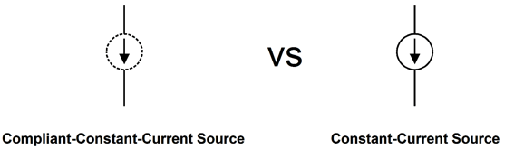
Hold on John, that's the exact same schematic as was shown before. No, it cannot be, as the symbol differs. Just as we need a new acronym, we need a new electronic symbol. The I use in my notebooks is this:
I am not crazy about it. For example, I don't like the implicit endorsement of the "conventional" notion of current flowing from positive to negative, in spite of the reality of electrons flowing in the opposite direction. Okay, enough complaining and let's replace the new CCCS symbol with an actual circuit that fulfills the CCCS function.
The top MOSFET works to split the B+ voltage and yet offers a very high impedance. If the bottom MOSFET idles at 2A, the CCCS will also idle at 2A; if the bottom MOSFET idles at 3A, the CCCS will also idle at 3A. In terms of current, it is compliant. In both cases, the CCCS and the output MOSFET will split the B+ voltage. Of course, this is only one possible circuit configuration. Here is another.
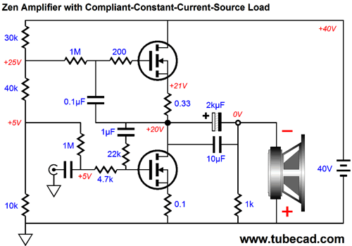
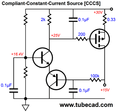
Here a differential amplifier made up from the two NPN transistors monitor the MOSFET's drain voltage, comparing it to the DC voltage from the two-resistor voltage divider on the left. and then adjust the MOSFET's current conduction so that matches that of the load. Note the 2.8k emitter resistor shared between the two transistors. Why no CCS in place of the 2.8k resistor? One could certainly be used, but why bother when we are concerned only with DC functioning. Here is another example:
This time, an OpAmp is used to control the N-channel MOSFET's Idle current and output voltage. The OpAmp's positive input sees the B+ divided by 2 and summons its considerable open-loop gain to establish the exact same voltage at its inverting input. In AC terms, the N-channel MOSFET is free to swing up and down, its source following its gate, which follows its CCCS output. The diode and the 200-ohm resistor that attaches to it are safety devices, which only really come into play at turn-off, when the B+ voltage collapses, but the 0.1µF capacitor to ground still holds a voltage charge. Here is a CCCS that uses a bastode circuit to control the MOSFET's current conduction.
Do not despair, if you believe that the CCCS is an exclusively solid-state circuit, as the following schematic shows that tubes can also be used.
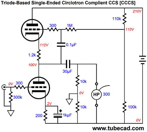
The impedance presented by this triode-based CCCS is equal to Z = ( rp + (mu +1) Rk) || 1M where Rk is the top triode's cathode resistor; in this example, 1.2k ohms. With a 6DJ8, the impedance would roughly equal 42k, which while not close to infinity, is still very high, as a 42k resistor would drop 420V with a 10mA current flow, a thing impossible with a 210V power supply. Now, be sure to bear in mind how triodes are different from pentodes, transistors, and MOSFETs, in that they exhibit a low plate resistance. This feature allows us to build the following circuit, without the fear that the bottom triode will neither get too little or too much plate voltage.
Where a CCCS truly comes in handy is when you already have a CCS in the current path; for example, the following circuit.
It's seldom a good idea to place two CCS in series, as you almost never get the voltage division that you expect. In the above circuit, that problem doesn't occur, as the CCS (the bottom MOSFET) sets the idle current for all three MOSFETs. The CCCS (the top MOSFET) sets the desired voltage division and matches the current flow through the other two MOSFETs. In many ways, the above circuit is functionally identical with the following circuit.
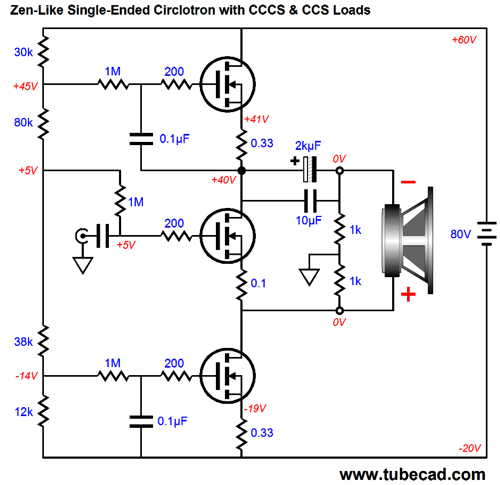
I assume that high-quality inductors (chokes) are being used, the type with low DCR. If you run some SPICE simulations of the above topology, you will be surprised by how little inductance the inductors must present to allow bandwidth down to 20Hz with 8-ohm speakers. Let's now return to the Zen-like, single-ended, current-out amplifier, but this time with CCCS load instead of a CCS.
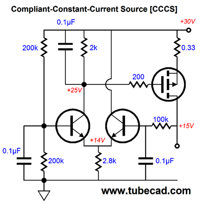
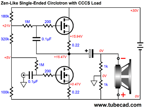
The CCCS ensures that the output stage will center at B+/2 at idle. Or, if we wish to create a Zen-like Circlotron, we use this circuit.
The load is split by the two 1k resistors and a Circlotron is created, an amplifier with a gain of 2 and low output impedance. Note that the power supply now floats, no longer being moored to ground. Next Time
For those of you who still have old computers running Windows XP (32-bit) or any other Windows 32-bit OS, I have setup the download availability of my old old standards: Tube CAD, SE Amp CAD, and Audio Gadgets. The downloads are at the GlassWare-Yahoo store and the price is only $9.95 for each program. http://glass-ware.stores.yahoo.net/adsoffromgla.html So many have asked that I had to do it. WARNING: THESE THREE PROGRAMS WILL NOT RUN UNDER VISTA 64-Bit or WINDOWS 7 & 8 or any other 64-bit OS. I do plan on remaking all of these programs into 64-bit versions, but it will be a huge ordeal, as programming requires vast chunks of noise-free time, something very rare with children running about. Ideally, I would love to come out with versions that run on iPads and Android-OS tablets.
//JRB |
I know that some readers wish to avoid Patreon, so here is a PayPal button instead. Thanks. John Broskie
Kit User Guide PDFs
E-mail from GlassWare Customers
High-quality, double-sided, extra thick, 2-oz traces, plated-through holes, dual sets of resistor pads and pads for two coupling capacitors. Stereo and mono, octal and 9-pin printed circuit boards available.  Aikido PCBs for as little as $24 http://glass-ware.stores.yahoo.net/
Support the Tube CAD Journal & get an extremely powerful push-pull tube-amplifier simulator for TCJ Push-Pull Calculator
TCJ PPC Version 2 Improvements Rebuilt simulation engine *User definable
Download or CD ROM For more information, please visit our Web site : To purchase, please visit our Yahoo Store: |
|||


| www.tubecad.com Copyright © 1999-2014 GlassWare All Rights Reserved |