| John Broskie's Guide to Tube Circuit Analysis & Design |
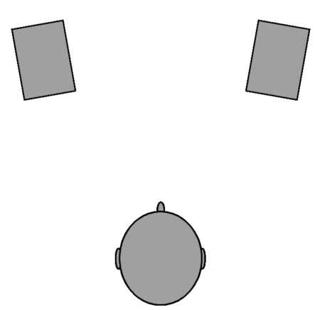
08 February 2012 Coupling Capacitor Shootouts By the way, just as some days are too sunny, too bright in the thin air high up here in Colorado and require sunglass clips, some recordings need sonic sunglasses. This is why I love being able to choose between coupling capacitors. My only regret being that I cannot choose between three or four different capacitors. Different recording, different artists, different recording labels—all require different sonic perspectives, which different coupling capacitors provide. The capacitor that sound best with James Taylor, may prove too romantic, too soft, too confused with a bright, fast string quartet by Dmitri Shostakovich. Yes, audio cables could provide the same functionality, but a much greater cost and extra hassle (and wear on RCA jacks). Of course, to the Absolute-Capacitor listener, such an idea is insane if not blasphemous—why would anyone listen to anything but the best. Best for what? is always my rejoinder. Ideally, I would love to own three or four complete audio systems, each optimized for a certain type of music: one system for small jazz ensembles, one for huge symphonic works, one for rock, and one for solo singer arrangements, perhaps. This last system might hold a center speaker that played a mono signal made equally of left and right channel information; the two flanking speakers would play stereo, but with a mixture of anti-phase opposing channel added to each, resulting in an exaggerated stereo, with a large hole in the middle, which the center speaker would fill. Such a setup would purposely be prejudiced in favor of the lone singer, as the singer's voice would primarily emerge from the center speaker, not equally from two speakers in the typical stereo setup.
Loudspeaker Diffraction Loss
An added advantage is that as the speakers are only three feet away from your ears, not a lot power is needed, nor do the speakers need to be huge and massive to play loudly. In fact, a small fullrange driver might prove the best performer. No crossover, no headaches. And the problem of small speakers not providing enough bass can be fixed readily enough with subwoofer and maybe one of those sonic-shaker modules that affix to the bottom of the chair. Failing that, a small bass-boost circuit can be used that compensates for diffraction loss at low frequencies. What is a loudspeaker's diffraction loss? (It really should be referred to as baffle gain.) Imagine that you held a small, 1 inch, fullrange driver with a sealed back in your hand and, amazingly enough, this driver had a flat output from 20Hz to 20kHz. If you placed this driver in the middle of the room, between floor and ceiling, the frequency response would be pretty much flat from 20Hz to 20kHz. Now if you mounted the driver on the center of a large panel, say two feet wide, the frequency response would get skewed, the lows remain undisturbed, but the higher frequencies would get a boost, as at these higher frequencies the sound primarily projects forward, which could readily be established by standing behind the driver and panel and listening. Thus, from behind the speaker, we would still hear the deep bass, as the panel's dimensions are small relative to the wavelengths, but the highs would be gone, as the panel would be large relative to those shorter wavelengths. Since the driver has only half the space to fill with high frequencies, the highs get a +6dB boost. Well, every speaker enclosure performs a frequency-selective augmentation to the higher frequencies. But then, so does the speaker's placement within the room, but at the low frequencies. Place the speaker on the floor and the bass gets a boost; place it where the floor meets the wall, a bigger boost; and placed in the very corner, the bass gets a huge boost. It's a mess. But at least with near-field listening its less of a mess, as diffraction loss is the only major problem to be solved. Fortunately, the following passive circuit can fix this problem.
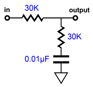
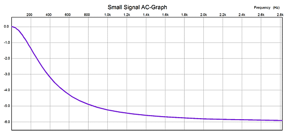
This shelving network effectively produces a +6dB boost of low frequencies by applying a frequency-dependent attenuation of high frequencies. The -3dB point occurs at about 375Hz with the above values. The greater the resistor value, the lower the transition frequency.
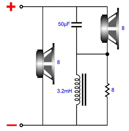
The formula is simple: C = 159155/1.414/Resistor/Frequency where C is in µF and both resistors are equal. The formula for finding the baffle's -3dB frequency is roughly: F3 = 13536/(3 x Width) where the baffle Width is in inches. Or we could tackle the problem of the loudspeaker's diffraction loss within the speaker itself. For example, imagine two identical fullrange drivers mounted in a small box. We want the two both drivers to cover the low frequencies, but only one to cover the full span of audio frequencies. The following network achieves this end.
The result is a 4-ohm loudspeaker, where one driver (the one on the left) sees all the frequencies and the other sees only low frequencies up to 400Hz. This will result in +6dB boost in the bass, but as the enclosure will produce a -6dB cut in the bass, the result will be a flat frequency response. (Of course, the above trick could be used in a more complex speaker, say one with two woofers and a tweeter.)
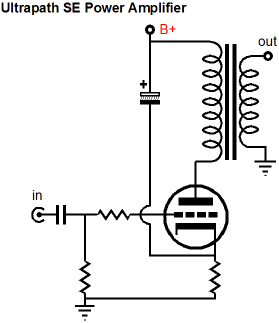
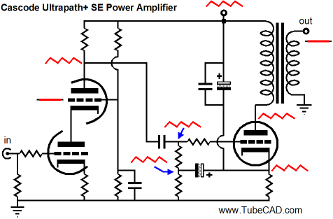
Making the Ultrapath Work with Push-Pull
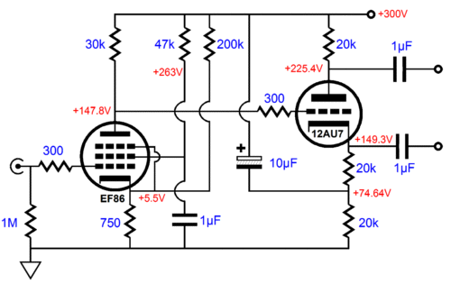
Usually, the Ultrapath capacitor is added to a single-ended output stage, but it can be used in a push-pull power amplifier. Thus, the Ultrapath shifts the output stage's signal reference from ground to the B+, which requires that input and driver stage's output signal must also be B+ referenced, else the power-supply noise will at best leak full-strength into the amplifier's output; at worst, this noise will be greatly amplified. In other words, we need an amplifier frontend with a zero PSRR, rejecting none of the power-supply noise, passing it along superimposed upon its output signal in its entirety. The following circuit illustrates a frontend with zero PSRR.
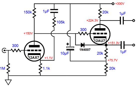
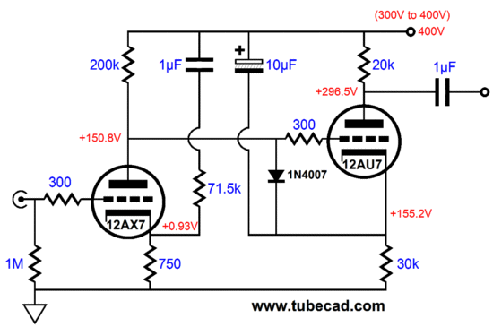
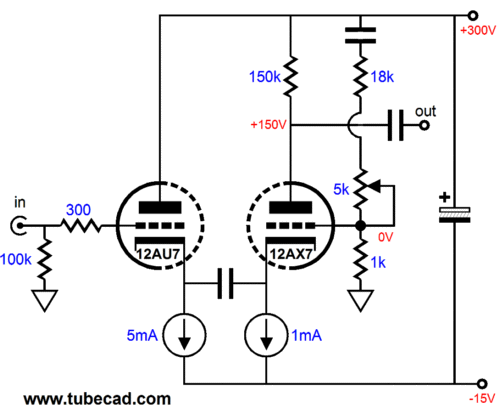
The pentode input stage starts with a poor PSRR figure, but the added 200k that spans from cathode to B+ decreases the PSRR to 0dB. The split-load phase splitter starts with near zero PSRR at its plate output and the 10µF capacitor couples the B+ noise to the bottom of its cathode resistor. Think of the split-load phase splitter as being nested in bubble that is referenced to the B+ connection, not ground. The EF86 is a great little low-noise, low-distortion pentode, but it doesn't provide a lot of gain. Fortunately, there hundreds of other small pentodes to choose from. On the other hand, there are also many excellent (and dirt cheap) dissimilar tubes, which hold a pentode and a triode within the same glass envelope, such as the 6AN8, 6AU8, 6AW8... The key feature to look for is a sharp-cutoff pentode section. Of course, many cannot abide the thought of using a pentode, so the following triode-based variation on the zero-PSRR circuit will be welcome. (I would use a 12DW7 in a mono amplifier and 12AX7 and 12AU7 or 12AT7 tubes in a stereo amplifier.)
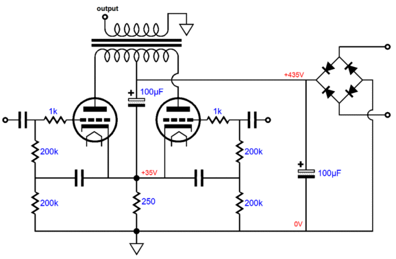
Just like its pentode brother, this circuit uses the input tube's cathode to inject some of the power-supply noise, in phase, to be amplified at the plate. On its own, the 12AX7 would define a 50% voltage divider with its 150k plate resistor, which is only half of what we need. The 1N4007 diode is an essential protection device, as at startup, without the diode, when the tubes are cold, the 12AU7's grid would be at +300Vdc, while its cathode would be at 0Vdc; not a good idea. Once the tubes are hot and conducting current, the diode falls out of the circuit, as it becomes reversed biased. Cheap and safe, what's not to like? (Yet, you cannot imagine the amount of hand wringing including this protection diode induces in the audio-nervous. The other absolutely essential circuit element is grid-stopper resistors, which prevent tubes from oscillating, but produce an agitated distress in high-strung audiophiles.) A suitable push-pull output stage for the either zero-PSRR frontend would be the following.
Triode output tubes are shown, but triode-connected pentodes, such as the EL34 or KT88 or 6550, or pure pentodes can be used. The key feature is the 100µF capacitor that AC connects the cathodes to the B+ connection, as that is what defines the Ultrapath technique. I added the two capacitors to the coupled cathode and the four 200k resistors to ensure that all the B+ noise was present on the output tube grids. Note the much higher B+ voltage in this output-stage circuit, which means that the pentode-based frontend would need some part value adjusting to work with the higher B+ voltage; the triode-based frontend, on the other hand, wouldn't, as the higher B+ voltage just scales up all the voltage values perfectly, well, close to perfectly. And remember, no power-supply RC filter can be used between the output stage and frontend, as both stages must see the same amount of B+ noise. Also note the 250 common cathode resistor for the two output tubes. One danger is that if one output is pulled from its socket or has its heater element open, the other output tube will not get enough cathode voltage to limit its idle current to safe amount. The workaround is to use a 12V heater power supply (or AC winding) and place both output tube heaters in series, assuming that each is a 6.3V heater. This way, if one tube is absent, the other will not get hot. While on the topic of the common cathode resistor, note how this resistor is performing double duty, as it both establishes a bias voltage for the output tubes and it works as an RC filter with the 100µF capacitor to the B+ connection. This is, in my estimation, the best feature of the Ultrapath technique. Well, we can readily see that the bigger the resistor value, the more effective the RC filter becomes at filtering away ripple. So, why not replace the cathode resistor with a constant-current source, which would approximate an infinitely large resistor value? One problem, if it is a problem at all, is that the output stage will be confined to class-A operation. As I say, I don't see this as big negative, as better to have half the soup at twice the flavor. On the other hand, the trick of placing a zener diode (with a break voltage slightly higher than the idle cathode voltage) in parallel with the constant-current source (or plain cathode resistor) will allow class-AB operation, but with reduced PSRR at high-output levels.
Virtual Ground
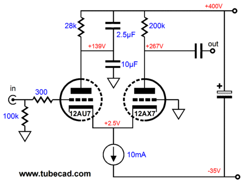
Note how we have created a virtual -35Vdc negative power-supply rail and a 400Vdc B+ voltage out of a single raw 435Vdc power supply. And note how we have effectively left Ultrapath territory, as the constant-current source absorbs all the power-supply noise, insulating the entire audio circuit from it, much in the same way if the CCS were located at the B+ connection.
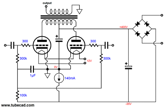
By the way, we do not have to use two noise-coupling capacitors at the grid circuit, as we can get away with just one capacitor, which the following schematic shows.
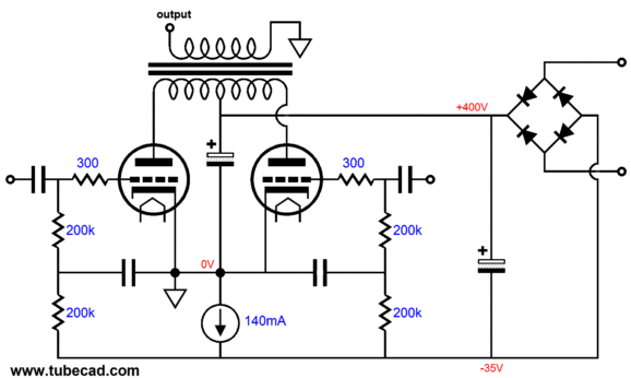
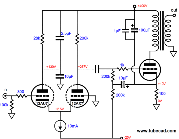
But since most tube fanciers believe the magic behind the Ultrapath lies in the capacitor that bridges cathode to B+, believing that it defines some ultra-special short power-supply loop, then for these audiophiles the topology is still belongs in the realm of Ultrapath. Also note how this trick, using a constant-current source to set the idle current and eliminate power-supply noise, works best within a monobloc power amplifier, as making a safe stereo amplifier gets tricky with two constant-current sources. By the way, I upped the grid resistor value to 300k in the last schematic, but the key change was the single capacitor from "ground" to the 100k resistor. Also note the two output tube heaters are in series. On the other hand, if a we use a true bipolar power supply, such as the following, then we squarely back in the land of Ultrapath.
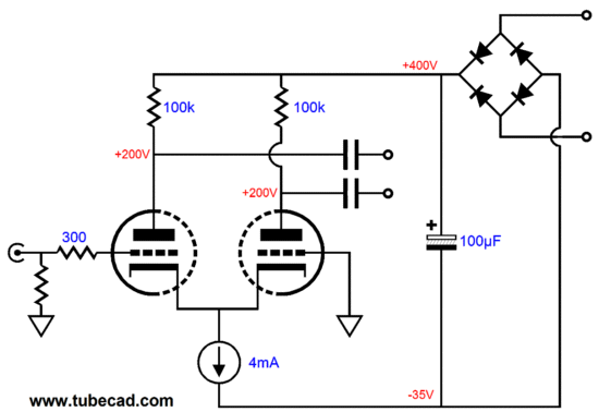
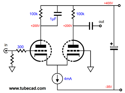
This simple tube-amplifier power supply will hold a good amount of ripple at both the B+ connection and the negative-bias rail. In addition to virtual-bipolar power supply's superb ripple filtering and auto-biasing of the output tube, this configuration allows us to use the following simple, but excellent input stage, without upsetting the auto-biasing of the output tubes. In contrast, the grounded-cathode amplifier cascading into the split-load phase splitter would upset the auto-bias feature, as it would draw current from the virtual ground.
This differential input stage also presents a PSRR of zero, 0dB. Think about it: if the constant-current sources forces a fixed current through the plate resistors at idle, then a fixed voltage must develop across them at idle, which means that all the power-supply noise must appear at the plates, as the plate resistors are effectively 200V batteries or voltage references at idle. From a meta perspective, however, we can see that we do not so much want a PSRR of zero from the B+ connection, as a stellar, near infinite PSRR from the effective -35V negative rail. Which tube should be used? I would use a 12BZ7 as the input tube, as it provides a high gain. A 12AT7 would also work well (as might a plain 12AX7). In this example, the input is unbalanced, but a balanced input signal could just as easily be used. Or we could use the right triode's grid for establishing a negative feedback loop that would extend to the output transformer's secondary's connection to the speaker. But since we can only expect a voltage gain of about 30 with a 12BZ input tube in the differential configuration, not a lot of negative feedback is possible. (Still, about 6dB of NFB could be realized with EL84 output tubes; or if we are willing to live with a 2Vpk input signal, then 6dB of NFB could be had with EL34s. And, of course, more with pentode-connected pentode output tubes.) (Since I was just writing in the whisper of parentheses, I will mention this: if we do not hook up a NFB loop, then there is no reason we have to ground one end of the output transformer's secondary. Instead, we can let it float or "ground" it to the house ground. Much experimenting is needed. Years ago, I experimented with floating the secondary and the output transformer metal structure, core and bell end caps, by using nylon washers and nuts and bolts.) I can imagine a glossy ad in an audio magazine that proclaims fantastic audio circuitry advances in and glorious sonics from such an amplifier—which is sort of true, but the interesting feature of such an Ultrapath push-pull power amplifier is how easy and cheap it would be to make. For example, two high-quality bias pots cost much more than a constant-current source based on the LM317-HV and big, expensive power-supply capacitors are not needed, nor elaborate choke-filled power supply filters. By the way, speaking of chokes, the solid-state constant-current source used on the output tubes could be replaced by a choke with a DCR of 250 ohms. And matched output tubes should be used (a workaround would be to give each output tube its own CCS or cathode resistor and its own capacitor to the B+ connection.)
Single-Ended Zero PSRR Frontend
Or we could use the following super high-gain circuit, which cascades two grounded-cathode amplifiers and would deliver a voltage gain of 700 (+57dB) with a 12DW7.
Such a high gain only makes sense when a negative feedback loop is in place. I wanted to show that even with such high gain a zero PSRR was possible. But is it sustainable? Not really. The solution would be to replace the 71.5k resistor with 10k potentiometer in series with a 65k resistor, so a noise null could be dialed in, no matter which 12DW7 was used. (Or, better still, two potentiometers in series, say a 10k and a 1k. The larger potentiometer would serve as the coarse adjustment and the smaller potentiometer as the fine control, much like in a microscope. The secret to easy operation is to center both potentiometers, then adjust the coarse potentiometer for a deep null in noise at the speakers, then adjust the fine potentiometer for the absolutely deepest null.) The final step would be to attach cascode or pentode-based or cascade frontend to the following output stage.
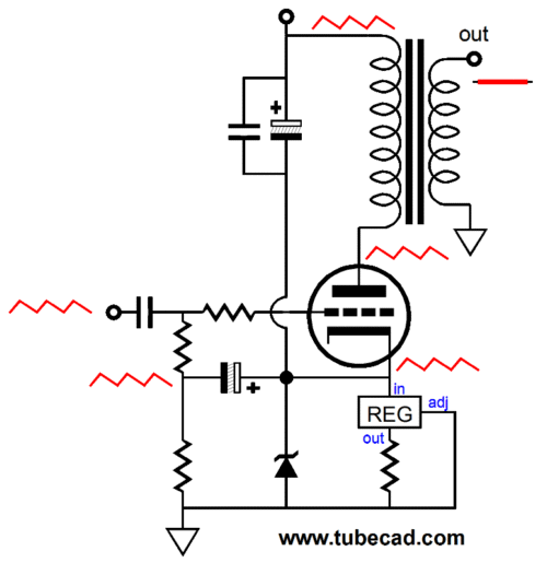
Of course, we can replace the solid-state constant-current source with a simple resistor, but since this amplifier must run in strict class-A, why not use the auto-bias feature that the CCS so easily grants us.
Virtual-Ground Power Supply and SE
The triode, once again, is a 12BZ7, which is a 12AX7 with twice the gm and half the rp; but other tubes could be used. Since the virtual ground is used only as voltage reference, this frontend will not upset the auto-bias feature. On the other hand, the cascode or pentode or cascade frontends would.
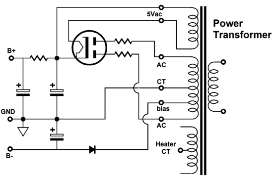
Standard Power Supply and Cathode-Coupled Fronted One workaround to the weak negative bias voltage rail is not to use and to add a true, full-wave negative power supply rail. This will require an extra power transformer, but at least it will be a small transformer. This more robust negative rail allows us to go wild. In fact, even dissimilar triodes could be used in the cathode-coupled frontend; for example, our old friend the 12DW7.
There is much to note here. First, the B+ voltage is 300V, not 400V. Second, the two-resistor voltage divider is necessary and a bit tweaky, so the potentiometer-resistor combination must be used here. The capacitor that bridge both cathodes can be a large-valued film type or a non-polarized electrolytic, such as those excellently made by Panasonic, but a plain electrolytic capacitor should not be used; we risk reverse polarity, if one input tube is removed or slow to warm up. (A MUR410G can be placed in parallel with an electrolytic capacitor to protect it.) If we plan on a B+ voltage greater than 300Vdc, then we can return to using two plate resistors. In addition, we must add a second bypass capacitor, as a single capacitor across the 12Au7's plate resistor will not yield a PSRR of zero.
The following is the amplifier fleshed out. The power supply has an additional negative low-voltage rail of -25Vdc and the output tube is is biased through a mix of fixed and grid bias. (Ideally, each input tube should get its own constant-current source and a capacitor should connect the two cathodes.)
So if I were to build an SE Ultrapath power amplifier, which circuit would I choose? I would stick to the first cathode-coupled amplifier circuit, with two identical triodes and two plate resistors, the left one being capacitor bypassed to the B+ connection and with the virtual-ground power supply configuration. You might be surprised to hear me say this, but we must avoid being anymore clever than we need to be.
Next Time
//JRB |
Kit User Guide PDFs
And
High-quality, double-sided, extra thick, 2-oz traces, plated-through holes, dual sets of resistor pads and pads for two coupling capacitors. Stereo and mono, octal and 9-pin printed circuit boards available.
Designed by John Broskie & Made in USA Aikido PCBs for as little as $24 http://glass-ware.stores.yahoo.net/
The Tube CAD Journal's first companion program, TCJ Filter Design lets you design a filter or crossover (passive, OpAmp or tube) without having to check out thick textbooks from the library and without having to breakout the scientific calculator. This program's goal is to provide a quick and easy display not only of the frequency response, but also of the resistor and capacitor values for a passive and active filters and crossovers. TCJ Filter Design is easy to use, but not lightweight, holding over 60 different filter topologies and up to four filter alignments: While the program’s main concern is active filters, solid-state and tube, it also does passive filters. In fact, it can be used to calculate passive crossovers for use with speakers by entering 8 ohms as the terminating resistance. Click on the image below to see the full screen capture.
Tube crossovers are a major part of this program; both buffered and un-buffered tube based filters along with mono-polar and bipolar power supply topologies are covered. Available on a CD-ROM and a downloadable version (4 Megabytes). |
|||


| www.tubecad.com Copyright © 1999-2012 GlassWare All Rights Reserved |