| John Broskie's Guide to Tube Circuit Analysis & Design |
|
||||
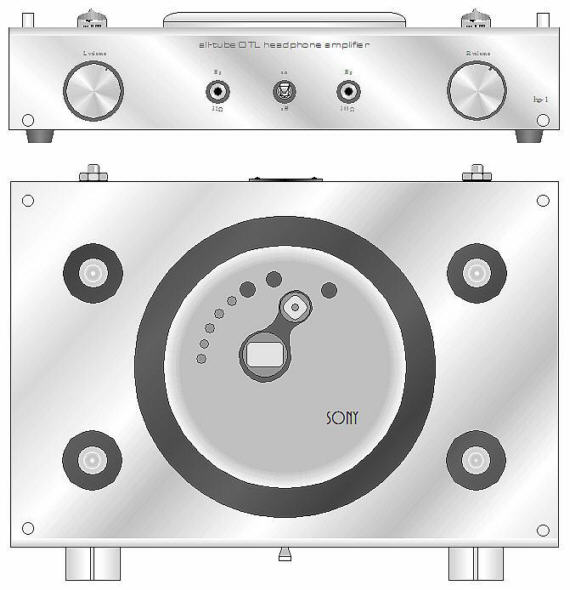
Tube Headphone Amplifier and Docking Station 3 April 2003 The bad news: my old portable CD player died; the good news: I picked up a new Sony D-FJ401. This new player runs forever on two AA batteries and offers 45 seconds of shock protection (which must be disabled for serious listening) and, most importantly, a line-out (which is increasingly rare these days). The player shares a desirable feature with the best solid-state equipment: its sonic failings are only subtractive. Seven voices reduce to three, large resonant halls transform into anechoic chambers, fingers lose their fingerprints when running across strings. Of course, this holds true for only the line-out, as the headphone output’s failings are additive, sounding gritty and coarse. Why the difference? The problem lies with the amplifier used to drive the headphones. In order to extend battery life, a class-B amplifier is used — which in itself is bad enough — but this amplifier is also a member of the ultra-low current consumption group that sounds even worse. Furthermore the amplifier can only swing half a volt, which while adequate for 16-ohm headphones, proves inadequate when driving 300-ohm headphones, such as the Sennheiser HD580s or HD600s. One solution I can envisage is a small tube-based headphone amplifier large enough to house the CD player. Above is a side profile of such an amplifier. The CD player sits on top of half-inch thick foam or felt and four tubes protrude through the chassis. An eighth-of-an-inch thick sheet of anodized aluminum wraps across the top and front of chassis, hiding the plain Bud box underneath. Inside the chassis, the power supplies for both the amplifier and CD player are housed. On the front panel, two outputs are offered: 32-ohms and 300-ohms, the 32-ohm output having a much-larger-valued coupling capacitor but, by necessity, a poorer-quality coupling capacitor. The power switch sits exactly in the middle of the front panel.
If Sony were to come out with such a tube amplifier and docking station, I bet it would sell well in Japan and Europe, as small, cute, and excellent are valued. Here, in the USA, however, Headroom could probably only sell a few hundred units, as most music lovers to whom I have mentioned this project have responded with, “Why bother? The player comes with a headphone jack.” (Maybe the fault lies with the same Midwestern outlook that allows boring cars to be made decade after decade. Don’t you love the new ads from the big two: “Our cars used to be much worse.” Imagine if Detroit wised up and did what Japanese car makers do: had their cars built in Michigan only after having been designed in San Diego. I went into a high-end audio store in Ann Arbor MI and looked around. Not a single tube to be found. I ask where the tube gear was hiding and the owner moaned and asked, “You’re not from California are you? Californians always ask that.”)
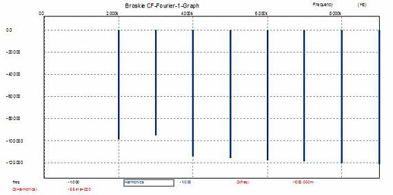
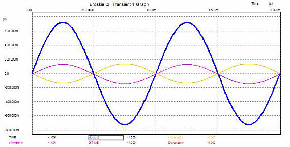
I didn’t think the circuit would work all that well into a 300-ohm load, so I modeled Bill’s implementation in Spice. WOW. It sure does measure well. The next step is actually to build the circuit and give it a listen with my HD580s. 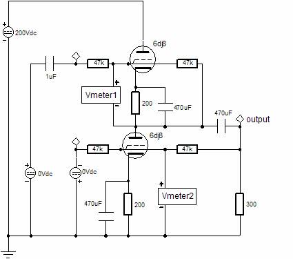 Of course, not every CD player has an XLR output, which limits this circuit’s appeal as a standalone headphone amplifier. But adding a grounded-cathode amplifier and a split-load phase splitter would be easy enough. As the output stage already holds a feedback loop, I don’t see the point of adding a global feedback loop, except for when driving 30-ohm headphones, so a switched feedback arrangement would be a good idea. So is this the circuit for the docking station? Maybe. But I still admire the simplicity and excellent performance of the grounded-cathode amplifier cascading into an optimal White cathode follower. The circuit results in a predictable gain and output impedance and an excellent PSRR figure.
So is this the circuit for the docking station? Maybe. But I still admire the simplicity and excellent performance of the grounded-cathode amplifier cascading into an optimal White cathode follower. The circuit results in a predictable gain and output impedance and an excellent PSRR figure.
In the schematic below, we see the 12AU7 in a totem pole arrangement that results in a final gain of half the mu of the tube used. In this case, about 8. We also see an optimal White cathode follower that offers half of the output impedance of a single cathode follower. In this case, about 60 ohms. The PSRR is much better than 6 dB figure that a casual inspection implies, as the optimal White cathode follower presents half of the power supply noise to the bottom 5687’s grid, which matches the half of the power supply noise that the top 5687 triode sees at its grid. In other words, the noise cancels at the output.
//JRB |
Tube CAD does the hard math for you. This program covers 13 types of tube circuits, each one divided into four variations: 52 circuits in all. Tube CAD calculates the noteworthy results, such as gain, phase, output impedance, low frequency cutoff, PSRR, bias voltage, plate and load resistor heat dissipations. Which tube gives the most gain? Tube CAD's scenario comparison feature shows which tube wins. Windows 95/98/Me/NT/2000/XP |
|||


| www.tubecad.com Copyright © 1999-2004 GlassWare All Rights Reserved |