| John Broskie's Guide to Tube Circuit Analysis & Design |
|
31 January 2007
PCB update
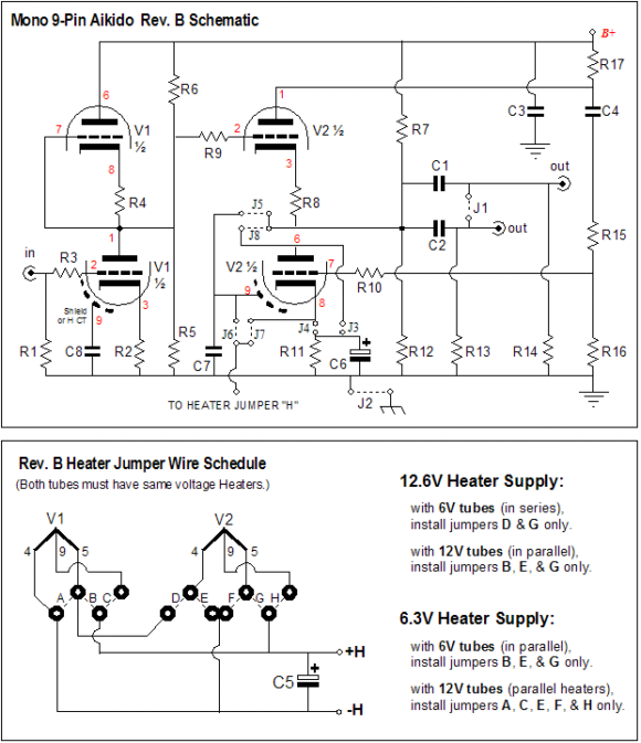
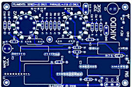
I was so taken back by the aptness of this wisdom-filled strip of paper to the long wait for the new PCBs that I completely forgot to append it mentally with the obligatory “in bed” ending. (Does everyone do that, or is that a local tradition?) At any rate, the wait is near over; all the new boards were made and shipped to me today. Now it will take about two days for me to fill and send out all the back orders. In the meantime, you can prepare for your Aikido project. Below is the new circuit and heater schematic for the mono PCBs.
Note all the new jumpers. Why so many? The Rev. B PCBs are more flexible than Rev. A, as they now can accept many more output tubes, such as the 5687, 6900, 7044, 7119, 7370, 7892, and E182CC (and of course, the old standards, such as 6AQ8, 6BQ7, 6BS7, 6DJ8, 6CG7, 6GM8, 6H30, 6FQ7, 6N1P, 6N27P, 12AT7, 12AU7, 12BH7, 12DJ8, 12FQ7, 5963, 5965, E80CC, ECC81, ECC82, ECC83, ECC86, ECC88, and ECC99). In addition, the heater arrangement has been redesigned so that many more input and output tube combinations are now possible. For example, the 9-pin mono boards can be used with 6.3V and 12.6V power supplies, as the heater jumpers allow tubes like the 12AX7 and 12BH7 to be wired as 6.3V tubes. In other words, it is now possible to use a 12AX7 as the input and a 6DJ8/6922 as the output tube (this has always been possible with the stereo 9-pin boards). Speaking of the Aikido stereo 9-pin boards, they have been revamped into Rev. B as well. The changes were not as bold as in the mono boards, but the small changes will be welcomed by many. For example, all the tubes now find a few ventilation holes under their sockets; the layout has been tidied up a bit; two new jumpers have been provided, so that the two output coupling capacitors can be bridged on the board; and holes have been added to the sides of the capacitor C!, the large out coupling capacitor, so that a tie wrap can be used to secure the capacitor to the PCB. Moreover, the output stage’s bottom triode can now have its cathode resistor bypassed. Why would someone want to? Many have used 9-pin stereo boards as the foundation of a headphone amplifier and now it will be easy to build the following circuit.
Broskie OTL update
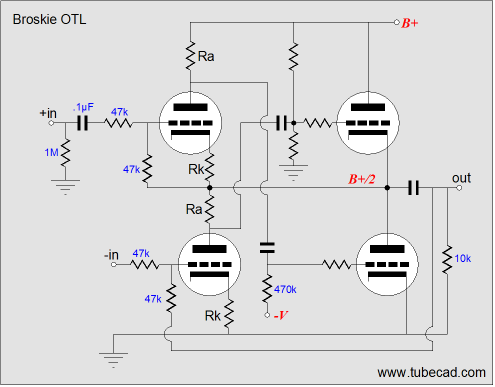
Soon after creating the Broskie OTL, my first thought was, "How good a headphone amplifier would it be?" The schematic below shows one possible arrangement.
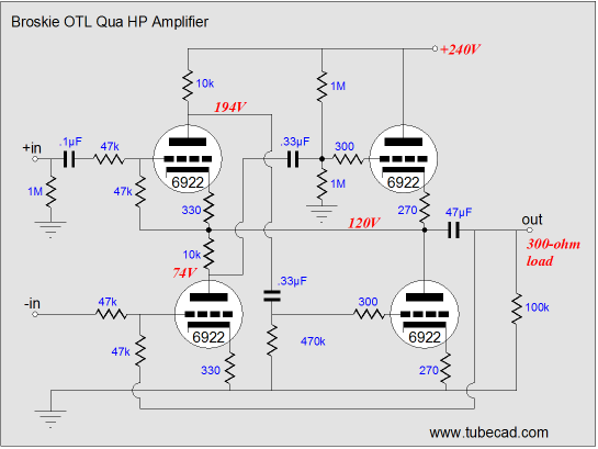
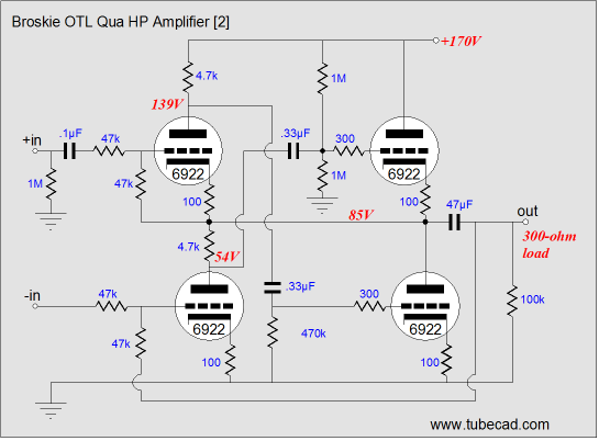
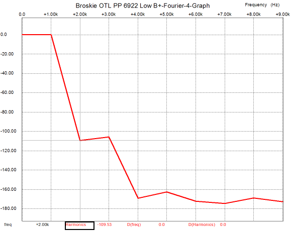
The 6DJ8/6922 triodes are moderately stressed by the 120V cathode-to-plate voltage that each experiences. But the more I thought about it, the more I wanted to design a lower-voltage version; I had been telling so many tube-based headphone amplifier builders to use a power isolation transformer to develop the B+ voltage, I felt I should heed my own advice. So the circuit was redesigned to work with only 170V worth of B+ voltage, as shown below.
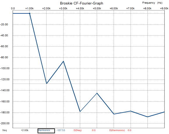
Well I finally got around to running a few more SPICE simulations on the Broskie OTL circuit. Interesting, indeed. The distortion is quite low, as we would expect from the higher open-loop gain that it realizes compared to the simpler Broskie cathode follower, for example. What I didn’t expect was the harmonics to reveal a single-ended influence. Usually, a push-pull amplifier’s harmonics look like a saw’s teeth, with the odd-order harmonics peaking high above the even-order harmonics.
What is going on here? My guess is that since both top triodes work in tandem to drive the load, just as both bottom triodes work together, the combined efforts yield a more balanced distortion signature than one would expect from a balanced, push-pull amplifier, with the odd harmonics only a tad bit stronger than the even harmonics. In other words, something is slightly out of balance here. Now, the question is, "Should it be set to perfect balance or should it be left alone, as its present sonic signature is more likely to please the ear?" A good question indeed.
So for those who always wonder to what good use a new circuit in this journal can be put, the answer is that many high-end line amplifiers, DACs, and CD players sport two types of outputs, balanced XLR and single-ended RCA jacks. This headphone amplifier could be used with the balanced output, leaving the single-ended outputs for driving single ended power amplifiers; or, it could be used in the recording or radio studio, where balanced feeds need to be rendered single-ended for headphone listening. Moreover, this circuit would work well with voltage-output DACs that offered balanced outputs, as its distortion into high-impedance loads is almost nonexistent (well, at least as far as SPICE simulations are concerned; reality will—no doubt—differ).
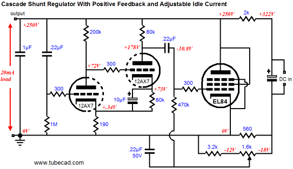
Feedforward shunt regulators update (Of course, there may have been many more that just could not get through my e-mail’s many layers of spam filtration. I have been on the sending end as well as the receiving end of this problem. This has become a huge problem for me and most other businesses. The statistic I have seen is that 80% of e-mail is spam. What happens when the percentage is 99.9%? Will any e-mail get through? The additional big problem I face is that the anti-spam algorithms are prejudiced against foreign-sent e-mail, which is about 80% of the e-mail I receive. What’s to be done? Okay, back to circuits, the question was, "How do you set up an adjustable-idle-current feedforward shunt regulator?" The answer is easy. Just take some resistance from the top voltage-dropping resistor and add it to the bottom series resistor; then add a potentiometer and a few resistors, as shown below.
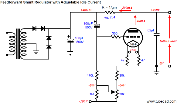
Or, what might prove to be a better solution: use fixed bias, instead of cathode bias. For those of you who switched over to solid-state rectifiers, here’s what you can do with the free 5Vac winding and the empty rectifier socket.
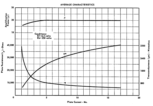
Yes, 300Bs are expensive, but no one would expect you to use an NOS WE 300B, just a cheap Chinese or East-European copy. (I love the idea of using three output tubes on a push-pull, monobloc amplifier; imagine a Dynaco MK-3 with three KT88s.) The real advantage to an adjustable idle current through the feedforward shunt regulator is that tubes differ from each other and from themselves over time. In other words, the perfect null that was achieved today, may not be perfect six months from now, or when a new tube is used. In addition, the feedforward shunt regulator differs from the average sloppily-built single-ended amplifier in that deep nulls require precise series resistor values. Here’s why: a tube’s transconductance is not a constant; like its plate resistance, it varies with plate voltage and cathode current. The graph below shows the relationships between rp, mu, and gm in a 6SN7 with a fixed 250V on its plate. The X-axis displays the current as the key variable. Note how the mu, the least real attribute of a triode, is the flattest, while the transconductance bends about.
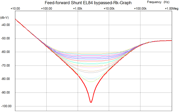
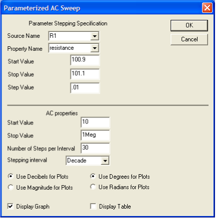
(By the way, a common complaint that I hear is that I always specify too high an idle current. For example, most tube gurus run their 6SN7s with only 1mA to 2mA of idle current, whereas I never go below 4mA, preferring 8-10mA. Guilty as charged. Now, let’s put this in perspective: the same tube fancier who whines on and on about the higher current halving the life expectancy of his tubes is usually quite happy to pay some tube guru $800 to change the coupling capacitors and sprinkle some magic dust over his preamp, although the guru’s modifications cannot come near to delivering the sonic benefit that derives from raising the triode out of its low-current mire. Just look at the graph and at the mu plot. Where does the 6SN7 become linear, above 5mA, or below? Where is the rp the lowest, at 1mA or at 17mA? Let's get real, here: at 1mA, the 6SN7’s rp is almost 40,000 ohms and its transconductance is a measly 0.4mA/V. What price does sonic glory come at? Current and voltage. Expecting sonic glory at low currents and voltages is like expecting a race car to get good mileage. In addition, the dreaded triode sleeping disease infects the tubes that are run too lean, not the ones that are run too hot. So a tube may last twice as long at the left side of the graph, but if sounds twice as bad, do you really want to listen to it for twice as long?) Back to the topic, to give you an idea of just how tweaky an adjustment is needed for a deep null, take a look at the graph below, which shows the results of a SPICE array of simulations with the series, voltage-dropping resistor’s value as the swept variable.
Note that the resistor's value starts at 100.9 ohms and ends at 101.1 ohms. The deepest null occurred at 101.0 ohms and is represented by the thick red plot line. Note the almost 40dB difference for a lousy 1 ohms! Since 1% resistors are not good enough for this degree of precision, adding a trimming potentiometer makes a lot of sense.
//JRB
|
Tube CAD does This program covers 13 types of tube circuits, each one divided into four variations: 52 circuits in all. Tube CAD calculates the noteworthy results, such as gain, phase, output impedance, low frequency cutoff, PSRR, bias voltage, plate and load resistor heat dissipations. Which tube gives the most gain? Tube CAD's scenario comparison feature shows which tube wins. Windows 95/98/Me/NT/2000/XP
For more information, please visit our Web site : To purchase, please visit Antique Electronic Sales' website:TCJ My-Stock DB Only $12.95
Download or CD ROM www.glass-ware.com
High-quality, double-sided, extra thick, 2-oz traces, plated-through holes, dual sets of resistor pads and pads for two coupling capacitors. Stereo and mono, octal and 9-pin printed circuit boards available.  Aikido PCBs for as little as $24 http://glass-ware.stores.yahoo.net/
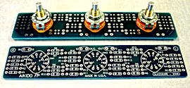
The TCJ Stepped Attenuator The center knob controls both channels, and offers six large decrements; the flanking knobs offer six fine decrements for each channel, creating a volume control and balance control in one easy-to-use stepped attenuator. This clever attenuator uses fewer resistors (only 32) than would be expected from a conventional 32-position stepped attenuator, as two series attenuators would need a total of 72 resistors; and two ladder attenuators would require 140 resistors. In addition, the PCB holds dual sets of resistor pads, one wide and one narrow, so that axial (composition, wire-wound, and film) and radial (thick-film and bulk-foil) resistors can be used without extra lead bending. Although designed to go with the Aikido amplifier, it can be used anywhere a high-quality attenuator is needed, whether passive or active. For example, it would make a first-rate foundation to an excellent passive line box. Visit our Yahoo Store for more details: http://glass-ware.stores.yahoo.net/
The Tube CAD Journal's first companion program, TCJ Filter Design lets you design a filter or crossover (passive, solid-state or tube) without having to check out thick textbooks from the library and without having to breakout the scientific calculator. This program's goal is to provide a quick and easy display not only of the frequency response, but also of the resistor and capacitor values for a passive and active filters and crossovers. TCJ Filter Design is easy to use, but not lightweight, holding over 60 different filter topologies and up to four filter alignments: While the program’s main concern is active filters, solid-state and tube, it also does passive filters. In fact, it can be used to calculate passive crossovers for use with speakers by entering 8 ohms as the terminating resistance. Click on the image below to see the full screen capture.
Tube crossovers are a major part of this program; both buffered and un-buffered tube based filters along with mono-polar and bipolar power supply topologies are covered. Available on a CD-ROM and a downloadable version (4 Megabytes). Download or CD ROM
|
|||


| www.tubecad.com Copyright © 1999-2007 GlassWare All Rights Reserved |