| John Broskie's Guide to Tube Circuit Analysis & Design |
05 August 2006
Transformer-Coupled Aikido Capacitors stink. And who—other than capacitor manufacturers and vendors—would argue otherwise? Yes, I know that resistors, inductors, transformers, and all active devices, such as transistors and, yes even, tubes also fall short in their own way. So, a more accurate phrasing might be: capacitors, relative to other electronic components, stink. 
Recently, I have conducted many listening tests, comparing the sound one type of coupling capacitor to another (as the only coupling capacitor in a single-ended amplifier).* The results? Each capacitor was a different disappointment. How did they disappoint? All capacitors dissatisfy and dishearten by adding to and subtracting from the signal. Trying to find a neutral coupling capacitor reminded me what it must have been like trying to buy good window glass before they figured out how to make it clear and flat. Yes, sometimes, certain portions of certain recordings sound better through a certain coupling capacitor, just like a fun-house mirror that stretches up and down make the short and fat happy. But other portions of the same recording and other recordings sound worse through the same coupling capacitor. James Taylor sounds best with one coupling capacitor, but Shostakovich string quartets sound best with another coupling capacitor… I know that some actually welcome and embrace sonic signatures. Like my brother who likes wearing rose-tinted sunglasses, some like the added flavoring that a coupling capacitor can bestow. One friend tells me that he would never buy a piece of audio equipment that wasn’t capacitor coupled at the output, as it would not allow him to tune the sound. Another friend is so in love with sonic painting with coupling capacitors that I sketched the following circuit for him.
The idea behind this circuit is that coupling capacitors can be added to capacitor-free outputs and that all the coupling capacitors will see a biasing voltage. However, even the most rabid capacitor lover isn’t going to argue that ten coupling capacitors in series sound ten times better than one coupling capacitor. Thus, a good plan is to use the fewest coupling capacitors possible; and many would argue that, optimally, no coupling capacitors be used. DC coupling from input to output works easily in solid-state electronics, but tube gear is seldom as lucky. High voltages must be sealed off from the outputs, a job that only a capacitor can do. But is this true? An output transformer can also block high DC voltages from the output. Additionally, the transformer can work as an electric lever, transforming low-current, high-voltage swings into low-voltage, high-current swings, something no capacitor can do. So, how can the Aikido be modified to accept an output transformer? (I know some are thinking that we will just swap bad capacitors for bad transformers. Up until a few years ago, I would have agreed. However, some of the best new transformers are quite good, for example the efforts from Tribute Transformers and others. And, if nothing else, new distortions are always preferred over old distortions—if the mind didn’t work this way, no one would ever remarry.) The above circuit is the obvious arrangement. The coupling capacitor, C1, is needed to block the B+/2 voltage at the output from saturating the output transformer. In other words, without the capacitor, the transformer’s primary would drag the Aikido’s output to a few volts above ground.
Air-gapped output transformers This circuit looks similar to the stock Aikido, but the underlying operation is quite different. The output stage’s bottom triode no longer actively bucks the power supply noise at the output; instead, it is effectively just a slow-to-conduct load resistor, which allows the current flowing through the top triode and output transformer to find a path to ground. The actual noise nulling is achieved by the voltage divider action resulting from power supply capacitors C1 and C2. Since the bottom triode only offers a slow turn-on, it can be replaced by a simple resistor. In fact, if we are willing to tolerate a small-valued coupling capacitor, the full B+ voltage can be used on the output tube, greatly increasing the potential output swing.
Non-gapped output transformers The two power supply capacitors, C1 and C2, once again work to null the power supply from the output by ensuring that the primary never “sees” the power supply noise from lead to lead. The price we pay is that the two power supply capacitors are in series, so their total effective capacitance is cut in half; but we do get to use two lower-voltage capacitors, which are smaller and cheaper than one high-voltage capacitor of the same effective capacitance. Another point to ponder: Is this line amplifier really coupling-capacitor free? Are the two power supplies not working as coupling capacitors, although to ground, not the output? A good question. My take is the power supply capacitors are always in the signal path, if they ever see any of the AC signal current; so, yes they are acting as coupling capacitors, but they were in all the previous circuits as well. Hence the 1.5µF bypass capacitors across capacitors C1 and C2.
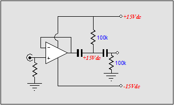
Bipolar power supply transformer-coupled Aikido amplifiers It isn’t. The idea here is that a bipolar power supply and an input coupling capacitor would set the Aikido’s output at ground potential, negating the need for a large-valued output coupling capacitor. The trap lies in assuming that the negative power supply rail is noise free. It isn’t. Imagine the input grounded. Then input stage’s bottom triode will see zero noise, but its cathode will see all of the negative power supply rail noise through its cathode resistor. The result is that the noise will be amplified by the mu/2. On the other hand, if we swap the input capacitor for an input isolation transformer, the noise will null at the output. The only fear I have is that the output will not center exactly at zero volts, as it is unlikely that the top and bottom triodes could be matched that equally. The following circuit allows for DC offsets.
Shunt regulators and transformer-coupled Aikido amplifiers
//JRB
*(I used to test coupling capacitors by using my Stax Lambda Pros and my own tube-based electrostatic headphone amplifier, which is direct-coupled at the outputs. I would place the coupling capacitors under test in series with the output and then I would compare the sound to the direct connection. Each egregiously painted a large sonic signature. Some clanked; others smeared; and a few seemingly added bass, while others seemed to subtract bass. No capacitor came close to matching the direct connection. Of course, it is a little odd to be driving what is effectively a capacitor—the electrostatic stators—with a capacitor. Normally, a coupling capacitor terminates into a resistor. Therefore, the electrostatic headphone test might have been too severe. By the way, I also tested the coupling capacitor under test with its output lead grounded. This allowed me to listen for “singing,” wherein the capacitor acts like a little Quad loudspeaker, producing a small acoustic rendition of the signal passing through them.) |
|


| www.tubecad.com Copyright © 1999-2006 GlassWare All Rights Reserved |