| John Broskie's Guide to Tube Circuit Analysis & Design |
| 10 October 2010 (That's 10/10/10 in any country)
New Output Stage Topology Variations In addition, beyond the goals of low cost, low complexity, low distortion, low noise, low output impedance, high safety, high reliability, and wide frequency response, OPS design must encompass thermal analysis and fault protection. On top of all this, the actual OPS will be the biggest, heaviest, and most expensive portion of the amplifier. Thus, most solder-slingers—quite wisely—prefer to leave OPS design to someone else, taking the a path of much less resistance, lifting the design examples listed in tube manuals and schematics of established power amplifiers. For me at least, if designing an OPS is difficult, then it is, for the same reasons, interesting, indeed, compelling. In addition, since power amplifiers impart the most sonic flavor, a new power amplifier also presents the most personality, giving us the chance to sonically taste something new, interesting, and, possibly, tasty. Coupling-Capacitor-Free OPS
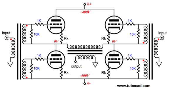
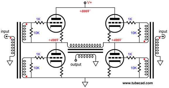
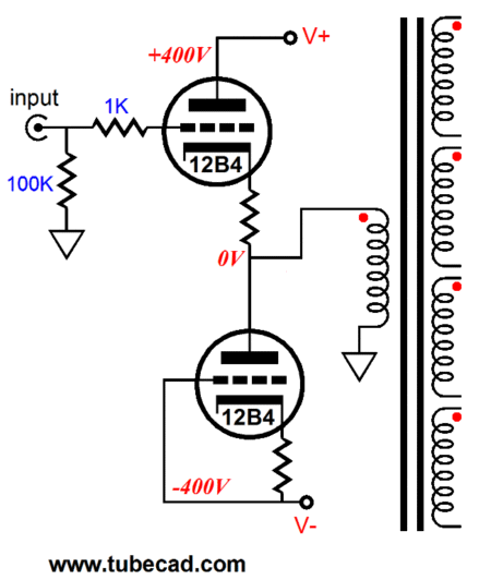
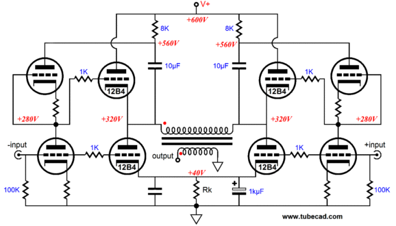
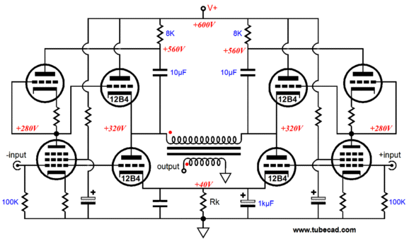
In the above schematic, we see no coupling capacitors and only four active devices (the four output tubes), all the other components being passive. The two transformers could just as easily be replaced by a single transformer, with four secondary windings, but two transformers would allow us to choose between balanced and unbalanced signal sources. The bipolar power supply is my preference, as it is four times less shocking than the equivalent monopolar power supply. How's that? Touching either the +400Vdc or -400Vdc power rail is four times less damaging than touching a +800Vdc power supply rail, as the lethal energy imparted rises with the square of the voltage. (Of course, bridging both bipolar rails with your body is as dangerous as the monopolar 800V power supply.) In addition, I like having the output transformer's primary and secondary at ground potential. Nevertheless, the exact same electrical performance would be realized by the following single-power-supply-railed amplifier.
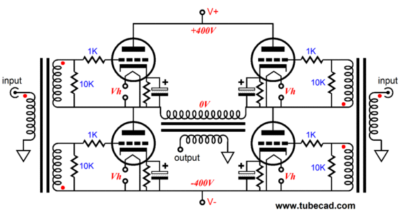
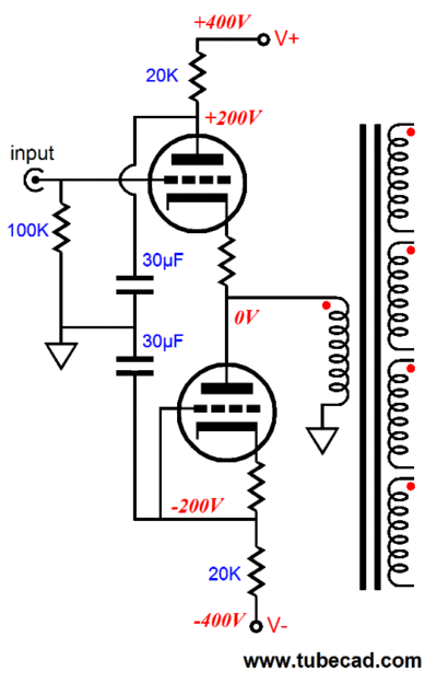
In both variations, the output tubes work in diagonal unison, wherein the output transformer's primary is pulled from the diagonally opposed tubes, while released by the other diagonal pair. So, unlike a conventional class-AB, two-tube, transformer-coupled, power amplifier, the whole of the primary is always engaged. This is a huge advantage, as half of the primary is never left flapping in the wind, as occurs in the conventional amplifier when one power tube cuts off, leaving only half the primary engaged. Four matched power tubes are required and just about any popular power tube could be used, such as the 2A3, 300B, 6BX7, 6L6, 12B4, 6550, EL34, EL84, EL86 and many more. Equal cathode resistors establish the bias voltage for the power tubes' grids and the 10k load resistors give the interstage signal transformers something to bite on. Assuming an interstage transformer winding ratio of 1:1, the reflected impedance at the input will be 2.5k for unbalanced signal sources and 10k for balanced (5k per phase). Higher-valued resistors could be used, but most likely at the cost of truncated low-end frequency response. Transformers are current-centric devices that work better the lower the terminating resistances are; in contrast, capacitors are voltage-centric devices that work better the higher the terminating resistances are. The higher the terminating resistance, the less capacitance needed, but the more inductance needed. In fact, sourcing high-quality interstage transformers would be the most difficult task in creating such an amplifier. Speaking of actually building such an amplifier, the following schematic shows something closer to actually working well in harsh reality.
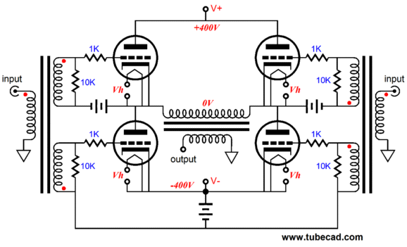
The top two output tubes will make huge cathode voltage swings, which will make maintaining a safe cathode-to-heater voltage difficult. In other words, each top output tube needs its own floating heater winding or DC power supply, referenced to the cathode. (The two bottom output tubes can share the same heater winding or DC power supply.) Bypass capacitors! I thought this was a coupling-capacitor-free design? The unbypassed cathode resistor may sound great, but steals gobs of potential watts from the output. Besides they are not, strictly speaking, coupling capacitors. Nonetheless, I, too, wish they were not there. One possible workaround is to build small, floating DC power supplies for establishing the bias voltage. Or, we could use batteries. Batteries? Audioquest uses small A23 12V batteries in their DBS polarized cables and, used singly or placed in series, they could be used to bias the output tubes, as shown below.
The batteries offer a stable, reliable voltage reference that presents a low internal resistance and wide operating temperature range, and a published shelf life of 3 years (probably much longer in actual bias-setting use). Eliminating the cathode resistors will, however, make tube matching all the more critical, as the resistors helped iron out differences between output tubes. Still, their elimination will boost the potential power output. A remaining hurdle to clear is the problem of driving this power amplifier to full output, as huge input signal levels will be required, from a low of 16Vpp for an EL84 to 80Vpp for a 6AS7. Additionally, the interstage transformer's load resistors will require a chunk of current, which leads to the following circuit, a DC-coupled, unity-gain buffer to drive the interstage transformer's primary.
Very few voltage-amplifier audio tubes can withstand a sustained cathode-to-plate of 400Vdc, which explains the use of the 12B4 in this circuit. Of course, if a 2A3 is used the output tube, then the resulting lower rail voltages, say +/-250Vdc, will allow a greater range of tube type options (I would look into using 5965 in this input circuit). Still, with big power supply rail voltages, a workaround would be the following configuration. Once again, the issue of exceeding cathode-to-heater voltage comes up again with this second circuit. That means that 30µF capacitors might be replaced by 200V zeners; or discrete triodes, such as the 6J5 or 6C4, might be the better way to go.
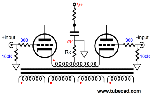
Balanced input could be implemented with the following circuit. The common cathode resistor (along with the primary's DCR) sets the bias voltage for the input triodes; the common plate resistor limits the triode's plate voltage.
Differential Gomes Amplifier
The above circuit certainly looks promising. No coupling capacitors. No interstage transformer. The top and bottom output tubes see dissimilar grid voltage swings, with the top triodes getting the big share. Although the above circuit may work well as a voltage amplifier, as a power amplifier it fails its aim. Why? The top output triodes function as cathode followers, whereas the bottom triodes work in the grounded-cathode amplifier configuration. This fundamental asymmetry produces a profound imbalance in the current conduction between top and bottom output tubes, leading to reduced output and high distortion. Balanced, symmetrical operation of all the output tubes requires that all the output tubes function as cathode followers or as grounded-cathode amplifiers. Achieving the former would be difficult, as the output tubes would have to see some feedback mechanism that relayed the entirety of the output signal on their plates back to their grids. Achieving the latter is somewhat easier, as we could add two bootstrap capacitors that would undo much of the top output tubes cathode follower functioning.
The 10µF bootstrap capacitors increase the gain from the input stage tubes and erase much of the top output tubes' low output impedance at their cathodes, as much (50%) of any voltage perturbation at the output transformer's primary will be relayed back to the top triode's grids. Getting 100% of the voltage perturbation relayed is more than the triode input can deliver, as their own rp makes the totem pole pair function as a 50% voltage divider for any signal present on the topmost triode's plate. Now, if the bottom input were a pentode and the top tube a triode, much more than 50% would be relayed, but not 100%. (The pentode presents a much higher plate resistance than the triode, so the voltage division will favor the triode.)
Such an amplifier might be close enough to the ideal to sound quite good, but if we could realize the cathode follower functioning, rather than the grounded-cathode-amplifier functioning, of all four output tubes, the amplifier would reward us with both lower distortion and output impedance. Fortunately, the Broskie cathode follower offers a possible solution.
Broskie CF Amplifier
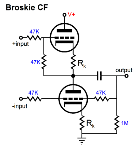
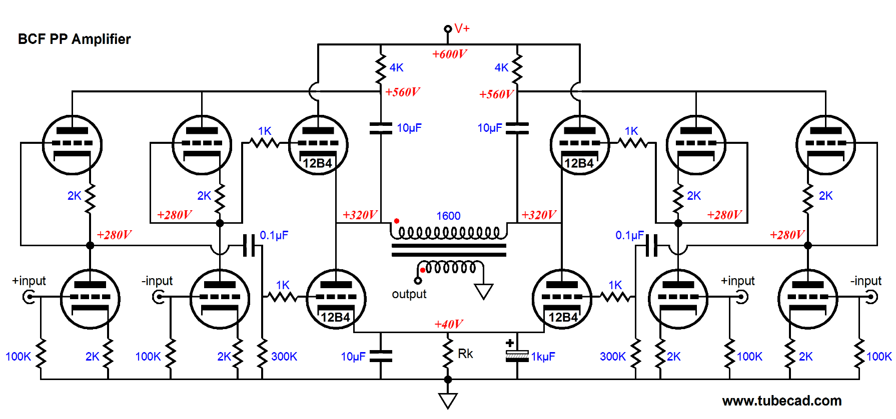
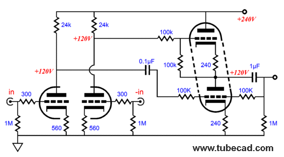
Of course, the resistors cannot be literally replaced, only functionally replaced, as the triode presents three nodes, whereas the resistor, only two. In the schematic below, we see two balanced, ground-referenced signal inputs (V1 & V3) and a single unbalanced output. The 10µF bootstrap capacitor relays the output signal to the plates of V2 and V4, whereupon the signal will be halved at V1 and V3's plates, as V1 & V2 and V3 & V4 both define 50% voltage dividers. Now imagine a 2Vpk, positive-going pulse applied to the output. V6's cathode will be driven 2V positive, but its grid will be driven 1V positive, decreasing V6's current conduction by -1V against its transconductance. On the other hand, output tube V5 will see its plate driven 2V positive, while its grid is driven 1V positive, provoking an increase in its current conduction by +1V against its transconductance. In other words, both top and bottom output tubes react equally against the imposed voltage pulse. The top tube bucks the pulse by conducting less, while the bottom tube conducts more. In fact, their combined efforts equal what a single triode would achieve configured as a cathode follower.
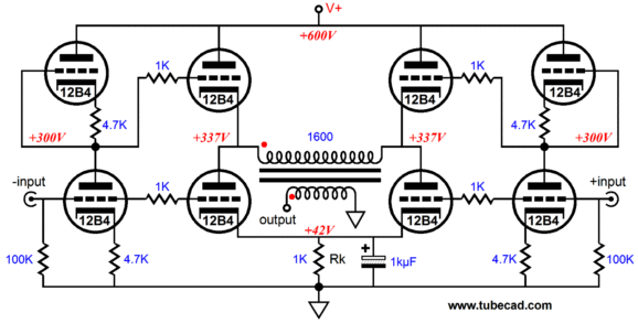
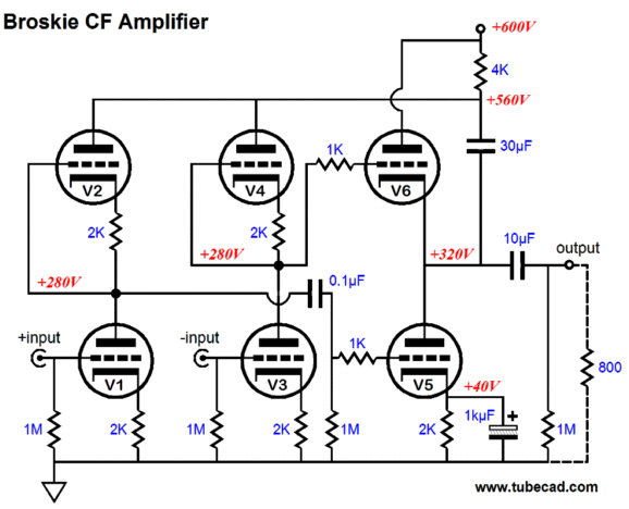
Before moving on, stop and marvel at how useful this circuit is, as it could be used to convert a balanced input signal into an unbalanced output, but with gain. Moreover this OTL power amplifier could readily be converted into a transformer-coupled design, which could drive 8-ohm loudspeakers. Cool, very cool. Yes, we lost the coupling-capacitor-free aspect, but we use only one coupling-capacitor. Why is the external load resistance set to 800 ohms in the schematic? The assumption was that two 12B4 triodes would be used as the output tubes, although just about any other audio power tube could be used, either triode or pentode. (In fact, if an extra coupling capacitor were added and two B+ rail used, then solid-state output devices could be used.) The 12B4 presents a plate resistance of about 800 ohms at 0V cathode-to-grid and 140V plate volts; thus the optimal load impedance would be 800 ohms. 140V? Why and where did the 140V come from? The latter is easy to answer: V5's 2k cathode resistor subtracts 40V from the 600V B+ voltage, leaving us with 560V to play with; and since the amplifier's output (before the 10µF coupling capacitor) halves the 560V, each output tube sees a cathode-to-plate voltage of 280V, which we halve again to get the 140V figure. But why do we halve it again? The biggest/optimal power delivery obtains when a voltage generator's output resistance matches the load resistance. For example, say you have built a squirrel house and you wish to heat it in winter by the voltage provided by a solar panel and the solar panel's effective series resistance and wire DCR add up to 1 ohm and the panel's output voltage is 2V. Inside the little house, what would be the optimal resistor value to place across the solar panel's wires to get the most heat? A low-valued resistor, say 0.1-ohms, would provoke the greatest current flow, almost 2A, but very little heat, as 2A² x 0.1 ohms= 0.4W. A high-valued resistor, say 10-ohms, would preserve the most voltage across the resistor, almost 2V, but, once again, very little heat, as 2V² / 10 ohms= 0.4W. The most heat is created when a 1-ohm resistor is used, as 1A² x 1 ohms = 1V² / 1 ohms = 1W. Finally, we arrive. Below, we see the full differential Broskie cathode follower power amplifier. The power transformer's primary sees zero voltage differential at idle, so the core does not need an air-gap. The primary reflects an impedance of 1600 ohms, as the plate resistance of two 12B4 output tubes equals 1600 ohms. The input/driver stage requires a balanced input signal and can be made from just about any high-voltage audio tube, such as the 6SN7, 12AT7, 12AU7, 12AX7, 12BH7, 5687, 5965, 6072, ECC99… The two voltage-dropping resistors (8k in this example, but should be closer to 4k) at the B+ must displace the same amount of voltage as the bottom output tube cathode resistors, otherwise the top and bottom output tubes will see dissimilar cathode-to-plate voltages.
How well does this new topology perform in SPICE? Quite well. With 6SN7 input tubes and a 1600-ohm primary and 28W of output at 1kHz, the distortion is below 1%. How does the little 12B4 put out 28W? In actual use, we would lose a few watts due to transformer losses and collapsing rail voltages. Still, the 12B4 is a powerful little triode. In fact Futterman built an OTL that used 10 of them to drive 16-ohm loads. Another way of looking at it is to imagine a conventional transformer-coupled, push-pull tube amplifier that used a B+ voltage of 300V and four 12B4 triodes. Running such an amplifier in lean class-AB, as we do with this design, would yield the same amount of output power.
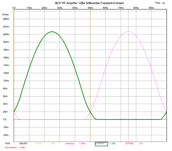
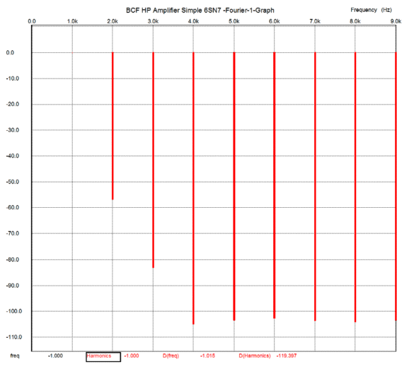
Note the classic push-pull harmonic structure, wherein the even-order harmonics are dwarfed by the odd-order. The push-pull current swing balance is excellent, as shown in the graph below.
The biggest mistake you could make would be to imagine that this topology must use 12B4 output tubes, as it could be reconfigured to use 300B triodes or KT88 pentodes.
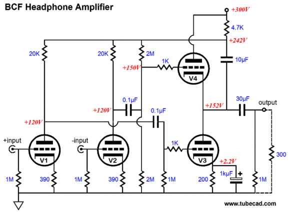
BCF Headphone Amplifier
The distortion's harmonic structure has a surprisingly single-ended flavor, which means that the balance between the top and bottom output tubes is off a tad.
This circuit would make an excellent unbalancing line stage amplifier, but I would build the following circuit instead, as it uses fewer capacitors and performs flawlessly as balanced-to-unbalanced converter with gain.
Next Time
//JRB |
E-mail from GlassWare Customers
High-quality, double-sided, extra thick, 2-oz traces, plated-through holes, dual sets of resistor pads and pads for two coupling capacitors. Stereo and mono, octal and 9-pin printed circuit boards available.  Aikido PCBs for as little as $24 http://glass-ware.stores.yahoo.net/
Support the Tube CAD Journal & get an extremely powerful push-pull tube-amplifier simulator for TCJ Push-Pull Calculator
TCJ PPC Version 2 Improvements Rebuilt simulation engine *User definable
Download or CD ROM For more information, please visit our Web site : To purchase, please visit our Yahoo Store: |
|||


| www.tubecad.com Copyright © 1999-2010 GlassWare All Rights Reserved |