| John Broskie's Guide to Tube Circuit Analysis & Design |
|
15 Aug 2009
Janus Solo
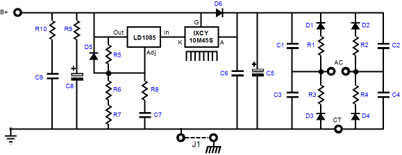
Note how a tube rectifier can be used with a transformer secondary that does not hold a center-tap, as adding solid-state rectifiers, D8 and D9, and resistors, R12 and R13, allow the non-tapped secondary to work with the tube rectifier by creating a full-wave bridge rectifier circuit. In fact, if two more solid-state rectifiers, D10 and D11, are added, the tube rectifier can be subtracted from the power supply.
PS-2 Solo On this extra thick (0.094 inch), US-made PCB with 2oz-copper traces resides a single high-voltage regulator, with its own raw power supply, including the rectifiers and power-supply reservoir capacitors. In other words, except for the power transformers, the PS-2 Solo PCB holds all that is needed to make a superb tube B+ power supply. The PS-2 Solo regulator can power a line-stage amplifier, headphone amplifier, or phono stage. (It might also work in a tube power amplifier, if the current draw isn’t excessive.) This high-voltage regulator uses a high-voltage series regulator to achieve a quiet and stable regulated B+ voltage, which can span from 50V to 300V, while delivering up to 100mA of current.
Furthermore, both a full-wave-center-tapped configuration and a full-wave-bridge rectifier arrangement can be used with this PCB. The PS-2 Solo PCB, like the Janus Solo PCB, holds only a single high voltage regulator, unlike the original PS-1 regulator PCB which held both high voltage and low-voltage regulators. Thus, the tube heaters must find their power source elsewhere, such as an AC winding or a simple DC power supply or regulator power supply. The PS-2 Solo kit (as will PS-1 kits from now on) comes with 14 voltage-setting resistors, which allows the following output voltages to be set.
Solo Regulator Kits The PS-2 Solo kit cost $49 and both the PS-2 Solo and Janus Solo kits are on sale at the GlassWare-Yahoo store.
Asymmetrical Amplifiers
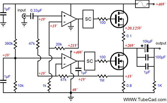
I can see his point, but probably for different reasons. My big worry is that the solid-state asymmetrical amplifier will clip harshly, like most solid-state power amplifiers. So if I were to give this design some more thinking time, I would strive to find a way to incorporate a soft-clipping circuit, such as the one I offered in blog number 66. Such a circuit would require breaking the global negative feedback loops. Or would it? Certainly the AC feedback would have to be curtailed, but what about DC feedback?
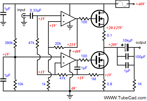
The above schematic shows a modified solid-state asymmetrical amplifier that no longer allows the OpAmps to reign over the power output devices’ AC performance, while still controlling the DC current flow through the output stage by establishing a fixed idle current by sampling the DC voltage drop across the 0.8-ohm source resistor via the 1M resistor. This asymmetrical amplifier presents clean drive signals to the top and bottom output devices and then lets these devices do their thing, without supervision. Now imagine two soft-clipping circuits being introduced between OpAmps and power MOSFETs. I am not sure what the bottom soft-clipping circuit would look like (no doubt, a few signal diodes and resistors), so let’s just use boxes (marked SC) to symbolize the hidden soft-clipping circuits.
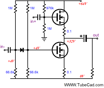
As I look at the above schematic, my mind travels towards another type of asymmetrical amplifier, a mixed mode push-pull power amplifier. Imagine a power amplifier that put out 4W in pure single-ended, class-A fashion; but when overdriven, would put out 16W of push-pull, class-A power; and when even further overdriven, would put out 64W of push-pull, class-AB output. Nice trick, don’t you think? Accomplishing such a feat of electronic magic requires using one output device as a constant-current source up to 4W of output and then letting it accept its input signal and swinging far beyond its idle current. Ten years ago, I showed how such an all-tube mixed-mode power amplifier could be made, using zener clamps and choke and constant-current sources; see tubecad.com/september99/page13 and tubecad.com/october99/page18. Designing a solid-state equivalent, however, might prove much easier.
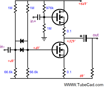
In the schematic above, we see the bottom output device blind to negative-going drive signals altogether and blind to positive drive signals smaller than 0.7Vpk. Once the bottom device’s positive input signal exceeds the signal diode’s forward voltage drop, the bottom MOSFET increases in conductance in response; its conduction never falls below its idle current of 1A. Within this 1A window of current, 4W of pure single-ended output can be developed into an 8-ohm load. Once the 1A threshold is reached, the bottom output device will pull down beyond the 1A boundary and the top device’s current draw will fall below the 1A idle current, eventually turning off altogether under large output signal swings. Adding a second signal diode will allow the power amplifier to enter class-B operation, as the bottom output device can now be fully cut off, as once the bottom device’s negative input signal exceeds the top signal diode’s forward voltage drop, the diode will conduct, allowing the bottom MOSFET to be turned off.
So what would be the big advantage of such a mixed-mode power amplifier? Great sound on the cheap, i.e. on the cool, the holy grail of high-end audio in other words. No longer would we worry that Al Gore might not approve of our stereo, no longer would our equipment rack have to support 200lbs, no longer would our amplifier use more aluminum than a motorcycle engine, as 1A of idle current against a 64V power supply rail only equals 64W of heat at idle, barely enough to keep a few cats warm. Had the peak output current swing been set as the idle current, as would have to be the case in a single-ended amplifier, the dissipation at idle would be 256W, as Iq would equal 4A. a push-pull, single-ended amplifier would require an idle current equal to half the peak output current swing, 2A, which would result in an idle dissipation of 128W. But would such a mixed-mode power amplifier sound as good as the pure single-ended or class-A push-pull amplifier? In absolute terms, no; but in relative to our pocketbooks, spouse-acceptance factor, global warming, and increased air conditioning bills in the summer, it probably would sound as good. Remember, most listening takes place in the first few watts, the rest being headroom. Bear in mind that the above schematic is a bit idealized, as the rail voltage would have to be about 5V higher to support 64W of output, 32Vpk, into 8 ohms.
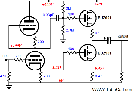
Rethinking the Hybrid Asymmetrical Amplifier
The tube is a 6DJ8 and the MOSFETs are BUZ901 types and the idle current is close to 1A.
//JRB
|
Kit User Guide PDFs
E-mail from GlassWare customers:
And
High-quality, double-sided, extra thick, 2-oz traces, plated-through holes, dual sets of resistor pads and pads for two coupling capacitors. Stereo and mono, octal and 9-pin printed circuit boards available.  Aikido PCBs for as little as $20.40 http://glass-ware.stores.yahoo.net/ Only $19.95
Download or CD ROM www.glass-ware.com
|
|||||||||||||||||||||||||||||||||||||||||||||||||||||||||||||||||||||||||||||||||||||||||||||||||||


| www.tubecad.com Copyright © 1999-2009 GlassWare All Rights Reserved |