| John Broskie's Guide to Tube Circuit Analysis & Design |
|
24 January 2007
Shunt Regulators Google lists 26 finds for the subject "Shunt Regulators" at the Tube CAD Journal Website. I expected more. A week ago I felt that I had said all that I could say on this topic; today, I see that only a small portion of possible circuit twists has been covered. (Besides, some differently-phrased repetition can only help the many who do not really understand this topology.) First, a quick recap and then we can move on to some interesting new shunt regulator designs.
Let’s start with some perspective. If you were a high-voltage regulator manufacturer, and if your adjustable voltage regulators had to provide a wide output voltage range, say 100V to 500V, and sustain a current draw up to 300mA, the last regulator topology you would chose is the shunt regulator’s. Why? Isn’t the shunt regulator the new, hot, must-have topology in high-voltage regulators? Here is the problem: you would never know which output voltage or current load the customer had in store for your adjustable regulator, details that are essential in a shunt regulator’s design. On the other hand, a series regulator can easily accept a wide range of output voltage and load currents. Why the difference? The series regulator, in a fundamental sense, holds only a pass device and raw power supply; whereas the shunt regulator holds a pass device, a raw power supply, and a series-voltage-dropping resistor. The fixed resistor rather assumes a fixed output voltage and current draw. Of course, we could use a variable resistor, like a rheostat or a resistor decade switching box; but even this workaround would not be ideal, as the setup that worked best with a class-AB, push-pull, power amplifier at idle would not be the setup needed for the same amplifier under heavy use. As I have mentioned here before, the shunt regulator can be likened to a class-A amplifier, while the series regulator is much more like a class-B amplifier. For example, a class-A amplifier dissipates the most heat at idle and is relieved when delivering power into a load; the class-B amplifier, in contrast, dissipates the least heat at idle. So it is with a shunt regulator’s pass device; it dissipates the most heat when the load is removed, as it must make up the difference in current conduction that would have been shouldered by the load. (The series-voltage-dropping resistor always dissipates the same heat with or without the load, as it effectively sees a constant-current source as its load.) Inversely, the series regulator sees the least dissipation when the load is removed, as it only needs to conduct enough current to establish its fixed output voltage. The moral of this story is "kind works best with kind." Class-A amplifiers warrant shunt regulators; class-B, series regulators. In other words, if the load current remains fairly constant, as it does in nearly every phono preamp and line-stage amplifier, use a shunt regulator. If the load current varies wildly, as it does in most power, push-pull amps, use a series regulator. (By the way, the ever popular capacitance-multiplier quasi-regulator falls into the series regulator taxonomy. These AC-only regulators are similar to the AC-only shunt regulators, in that neither type preserves a steady DC voltage, although both eliminate AC noise.)
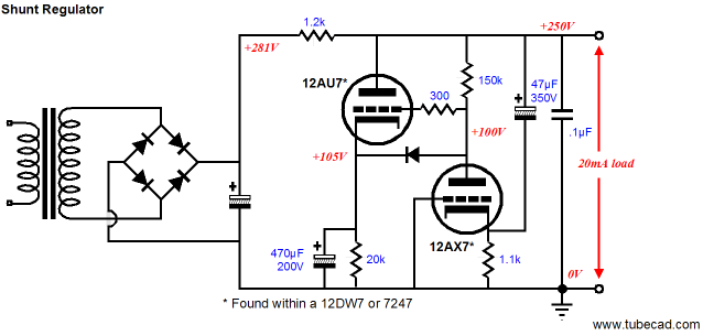
Common mistake Think of the shunt regulator as defining a two-resistor voltage divider, with the series resistor sitting atop the resistance defined by the inverse of the pass tube’s transconductance. For example, a 10k series resistor and a 6DJ8 are effectively the same as a 10k resistor in series with a 100-ohm resistor, whose voltage division equals R2/(R1 +R2), which in this example equals 0.0099, 100/(10,000 +1/0.01) = 0.0099. In other words, the most attenuation of the raw power supply’s noise is about -40dB, which isn’t that much (20mV), if 2V of noise sits on the rail voltage. Of course, some capacitance is always tacked on the shunt regulator’s output, so the attenuation can be much greater at high frequencies. In fact, 470uF of capacitance offers an impedance of 17 ohms at 20Hz, so the tube’s low-impedance contribution might be swamped out by the output capacitor. So what is the solution? Many more pass-device tubes? Higher transconductance tubes? While these solutions offer better performance, the easier and cheaper solution is to add a gain stage before the pass-device tube, so that its transconductance is effectively multiplied by the added gain. In addition, the inverse of the new effective transconductance will be the-added-gain-times lower. In the circuit below, we see a wimpy 12AU7, with a trivial transconductance of only 1.8mA/V, whose inverse equals 555 ohms. The 12AX7 saves the day by supplying an in-phase gain of about 62, which effectively increases the 12AU7’s transconductance to 110mA/V, whose inverse equals a bit less than 10 ohms.
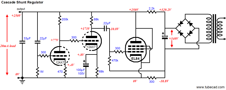
Achieving an even deeper attenuation of power supply noise requires more gain. I have shown how a modified cascode front end can yield high gain and wide bandwidth. Now let’s look at some cascading grounded-cathode amplifier circuits. In the schematic below, an EL84 provides the heft and the cascaded 12AX7s provide the extra gain.
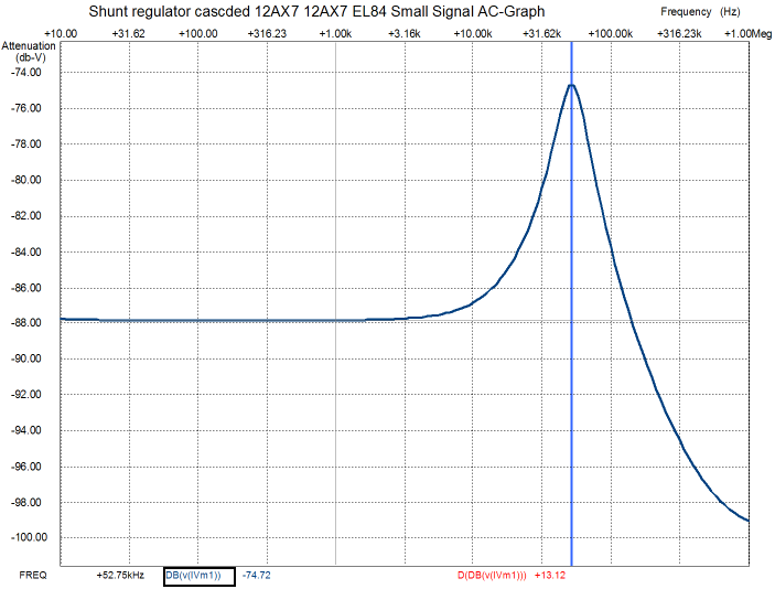
Below is a graph of the above circuit's attenuation of signal-side-induced noise on the B+ voltage rail. Note that lower and flatter is better.
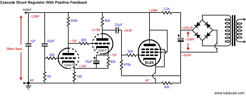
There is quite a bit going on in this circuit worthy of comment. First, note where the ground attaches: it does not connect to the main power supply filter capacitor; instead, it connects to the cathode of the EL84. Why? This trick allows us to turn a liability into an asset, as we do not have to provide a negative power supply to provide a negative bias voltage for the EL84, nor do we need to use a large-valued bypass capacitor across the 300-ohm cathode resistor. In addition, the 300-ohm resistor is effectively in series with the top 2.2k series resistor and both resistors buffer the active shunting portion of the regulator. The downside to this trick (yes, there is always a downside) is that the load current also flows through the resistor, so its value must be adjusted for each change in load current draw. In other words, this topology is not plug and play; instead, it is think, plug, and play. The second noteworthy feature is the direct coupling between 12AX7 gain stages. Why? This regulator employs a huge amount of gain to run what is effectively a unity-gain amplifier (whose input signal is ground). Coupling capacitors and inter-stage transformers introduce phase shifts, which if they tally up to 180 degrees, transform amplifiers into oscillators. Never a good idea. Thus, the elimination of one reactive component helps a great deal in ensuring stability. Having just warned of phase shifts within regulators, the following circuit would seem a dangerous proposal. Yet, it works quite well and, paradoxically enough, exhibits less high-frequency peaking than the previous topology and offers a slightly higher output impedance. One interesting and cost-cutting feature is the small-valued output capacitor, only 1µF, rather than 33µF from the previous design. More experimentation is definitely required.
Below is a SPICE graph of the above circuit's attenuation of noise on the B+ voltage rail. Note that there is no high-frequency peaking.
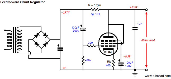
Feedforward shunt regulator EE Times's Website www.planetanalog.com offers an excellent article on this technique, in which the author notes, "A simple feed-forward noise-cancellation technique can reduce the supply noise by more than 26dB, while maintaining a low input-to-output voltage drop and high power efficiency." The circuit looks complex, but isn't. Resistors R3 through R6 simply set a DC reference voltage; capacitor C1 feeds all the power supply noise to the OpAmp, which establishes that same noise signal on top of resistor R1.
I know that at this point many of my tube-loving friends will tune out, shaking their heads at my silly compulsion to include solid-state design examples. As they tell me, “If it didn’t exist in 1935, it shouldn’t be used today.” In addition, we could append the phrase, “...and it shouldn’t exist today.” Well, if I searched long enough, I could probably find a pre-1935 example of feedforward-based tube circuitry, but I doubt even that would sway the hardcore there-is-nothing-new-under-the-sun fanatic. For the more mentally flexible, this technique presents some interesting results. The first step is to create a tube-based feedforward shunt regulator, preferably without the OpAmp. This means that we cannot use an exceptionally small-valued series resistor. But since we are not playing with 5V power supply and 10A current draws, we can afford to lose voltage in exchange for getting rid of power supply nastiness.
Note that the series resistor must equal the inverse of the tube’s transconductance. For example, assume that a 1-volt positive pulse appears at the left of the series resistor. This pulse will be relayed to the EL84’s grid in its entirety, provoking an increase in conduction equal to 1V times the tube’s transconductance. If, for example, the transconductance equals 10mA per volt, a 10mA increase in current will flow through the tube. This surge in current will then combine with the 40mA drawn by the load and the existing idle current flowing through the tube. When the added 10mA increase in current travels through the series resistor, whose value equals 1/0.01, or 100 ohms, the resistor will develop an increased voltage drop of 0.01 against 100, or 1V, forcing the B+ downward by 1 volt, except that the positive-going pulse raised the B+ voltage by 1 volt. In other words, a perfect null. Not bad for a single EL84.
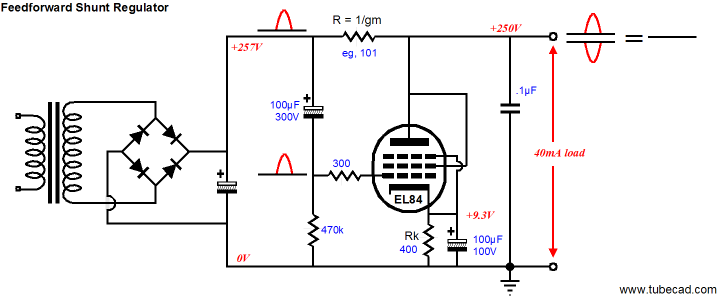
Now here is the truly marvelous aspect of this topology: any triode or pentode will work, achieving the same null, as long as the series resistor equals the inverse of its transconductance and that the idle current through the triode is sufficient to provide the needed voltage swing through the series resistor. Yes, a 5687 would be just as effective as a 6C33 or 845! Of course, common sense applies here. For example, a 12AX7 cannot be used with an OTL amplifier that draws peaks of 4A from the power supply; in fact, the 825-ohm series resistor that the 12AX7 requires cannot not sustain more than a few tens of milliamps before it consumes too much of the B+ voltage. For example, 40mA against 825 equals a voltage drop of 33 volts. So, once again, in general, a high-transconductance tube is preferred. Okay, are we done? Have we finally arrived? Well…one hassle is the cathode resistor’s bypass capacitor. It really should be large in value, in order to ensure good low-frequency noise cancellation. We can use the trick from the shunt regulator, however, and place the cathode resistor in series with the output.
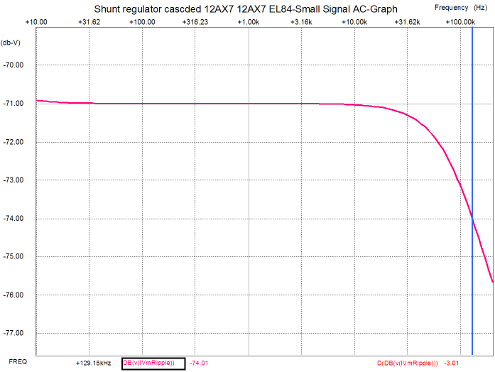
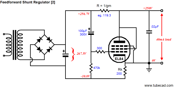
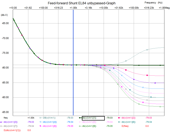
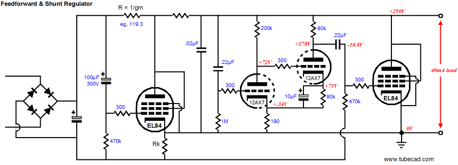
In the above schematic, note how the series resistor’s formula remained the same: R = 1/gm. Also, note the amazingly low-valued output capacitor, only 0.02µF. Why so low a value? Mostly because that’s all that is needed, as the SPICE-generated graph below shows.
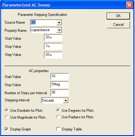
The setup for the SPICE array of simulations is shown below. The first sweep starts with a capacitor value of 0.01µF, with each successive sweep adding 0.01µF to the initial value, so the second sweep equals 0.02µF.
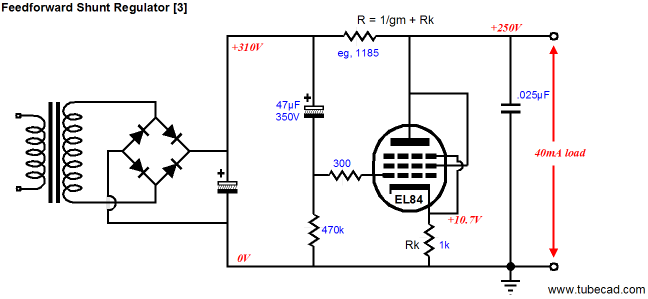
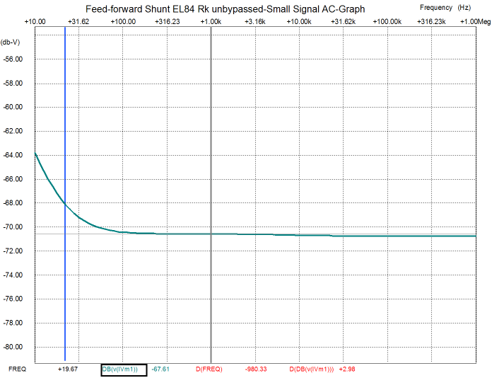
Wouldn’t a larger-valued capacitor just make things better, as it would offer a lower impedance to high-frequencies? I am not sure that it would. It just might be that a flat impedance across the audio band might make a better sounding amplifier than one with a frequency-dependent impedance. I remember being told by a capable high-end-tube-amplifier designer that he purposely soldered a 1-ohm resistor in series with the power supply capacitors. He argued that this trick neutralized the capacitor’s sonic signature, which resulted in a more even-sounding amplifier. Of course, what’s being attenuated is the raw power supply noise, not the signal-induced noise, so this argument may not hold here. Once again, more experimentation is required. Just for kicks, what happens when we use the cathode resistor in a conventional way and leave it unbypassed? The schematic below shows what I have in mind.
Below is the SPICE graph for the above schematic:
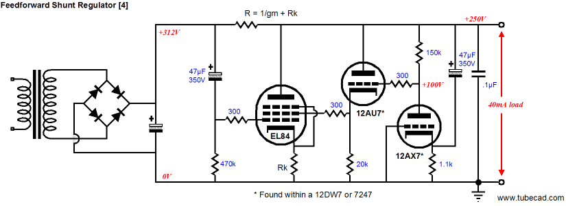
Note the bass. It is only up 3dB at 19Hz, whereas the other versions are up 10dB at the same frequency. Although I love the look of the flat line, it might be better to use a large valued bypass capacitor across the output, but then…maybe not. The downside to this topology is that the series resistor's value must be increased by the cathode resistor's value, making for a big voltage drop (sometimes, we have too much voltage and this big drop would become an asset). Great as the feedforward shunt regulator is at rejecting power-supply-induced noise, it does little to attenuate the signal-induced rail noise. The following circuit addresses that problem.
Remember that the EL84 holds two grids and that both control the flow of current through the tube. In the above circuit, we take advantage of the second grid. The 12AX7 triode is configured in a grounded-grid topology, which offers wide bandwidth and no phase inversion. The 12AU7 works in a cathode follower circuit and it directly drives the EL84’s grid number 2 with a greatly amplified rail noise signal. This might not be enough. What might prove best is to use both a feedforward shunt regulator and a conventional shunt regulator at once, so that the first may eliminate the rectifier noise and the second, the signal-induced noise caused by the different stages within the amplifier tugging and pulling on the B+ rail.
Next time //JRB
|
|


| www.tubecad.com Copyright © 1999-2007 GlassWare All Rights Reserved |