| John Broskie's Guide to Tube Circuit Analysis & Design |
|
21 May 2017 Post 380
Okay, this is embarrassing. In post 378, I mentioned that I used to be known as Mr. Ironclad Memory. Well, a lot of rust seems to have accumulated with the passing years. Back in 2014, I planned on devoting an entire post to the Different Differential amplifier. I didn't, but I thought that I had, as I had created the schematics and run the SPICE simulations (actually, I ran the simulations back in 2010). What's worse is that I have mentioned the circuit and the imaginary post in several email exchanges. I probably would have gone to my grave believing that I had made that post. I only discovered its absence after writing post 379 and I thought that I should have provided a link to the Different Differential amplifier; there isn't any. I did show the topology back in 2009 in post 166, however, wherein I showed it being used as the frontend for an electrostatic-headphone amplifier. In other words, after all email engendered by post 166 showed up 2009, I decided that make the Different-Differential post in 2010, got started with SPICE simulations, waited until 2014 to draw the schematics, thought I posted but didn't, found out last week that I hadn't, and finally posted now. As they say, better late than never.
Different Differential Amplifier
A differential amplifier uses both inverting and non-inverting inputs to amplify the voltage difference between the two inputs, while ignoring any signal common to both inputs. Usually, at least two active devices, such as FETs, MOSFETs, pentodes, transistors and triodes, are used.
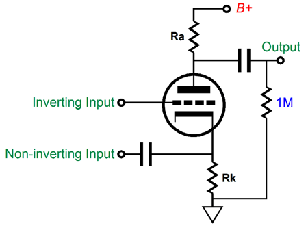
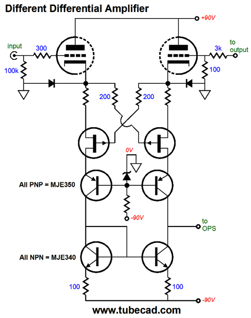
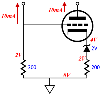
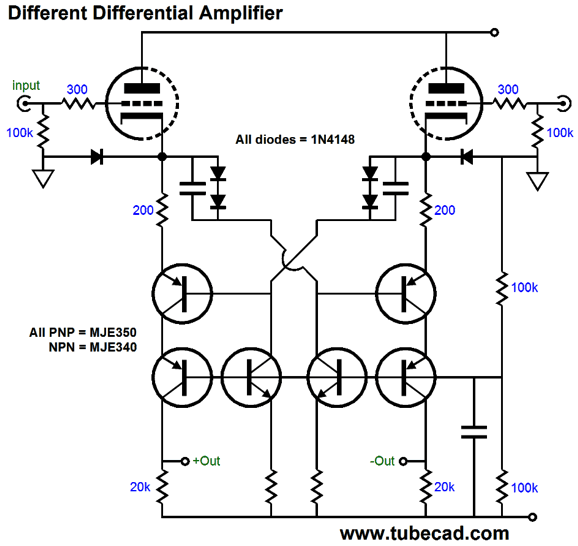
The advantage bestowed by the two identical devices is that the two input impedances match and the two output signals are balanced. On the other hand, we can use a single active device, such as one triode, as shown below.
The input impedances do not match and the output signal isn't balanced, but these features may not be required. The different differential amplifier functions like the conventional differential amplifier that uses two triodes and bridged cathode, but differs in that the output is taken below the cathodes and the two plates are bridged.
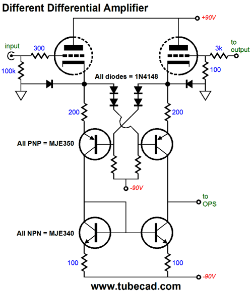
The two triodes offer extremely high input impedances and no Miller-effect capacitance, as their plates are locked at the B+ connection. Placing two forward-biased diodes in series creates a fixed—well, somewhat fixed—voltage drop. The two PNP MJE350 transistors perform the task of differential amplification, as each sees an input signal at its emitter and base. In other words, we have placed two transistor-based differential amplifiers in parallel but in anti-phase to each other. The result is a high common-mode rejection ratio (CMRR). At the bottom of the circuit, we see a generic current mirror, which offers a push-pull output of sorts—if you stop to think about it for a second. The two PNP MJE350 transistors could be replaced by two P-channel FETs.
Since high-voltage P-channel FETs do not exist, we protect the low-voltage FETs by adding the PNP transistors in cascode, which will shield the drains from the negative high-voltage. (The zener diode is not marked, but I would use a 12V device.) Both versions deliver the same high gain, insanely high, due to the current-mirror loading of the transistor collectors. Most tube fanciers do not know what a current mirror is, as I have discovered over the decades.
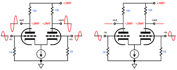
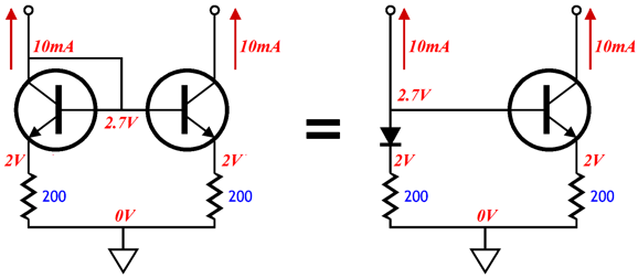
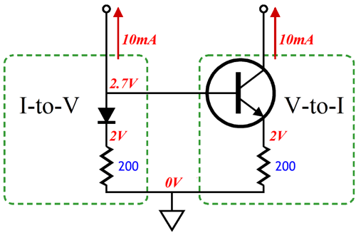
Most current mirrors are made up of two identical NPN or PNP transistors. In the example on the left above, the NPN transistor is functioning as a diode, as its base is tied to its collector. Indeed, this transistor can be replaced by a diode, as shown on the right. A current mirror is really two separate sub-circuits: an I-to-V converter and a V-to-I converter. A resistor is a current-to-voltage converter, its conversion ratio being set by its resistance. The formula is simple: V = IR.
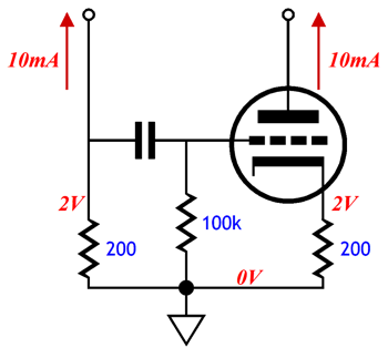
The NPN transistor and emitter resistor define a voltage-to-current converter, its conversion ratio being set by its emitter resistor's resistance. This is why we specify the same resistor value for both resistors. If the left leg of the current mirror sees an increase in current flow, then the right leg will increase its conduction to match the left side. A mirror, a current mirror, in short. We can make a current mirror out of a single triode and a coupling capacitor and a few resistors.
One problem with the above current mirror is that the triode offers a truly puny transconductance, unlike the NPN transistor. The result will be weak mirroring by the triode leg of the current mirror. The workaround is to increase the I-to-V resistor value. By how much? Prepare for some simple math. A triode's transconductance (gm) is equal to its amplification factor (mu or µ) divided by its plate resistance (rp), or gm = mu/rp. So, if a triode's amplification factor (mu or µ) is 30 and its plate resistance (rp) is 3k, its transconductance will be 0.01A per volt, or 10mA/V. When we add an unbypassed cathode resistor, however, the transconductance falls off. By how much? By this much, gm = mu / (rp + [mu + 1]Rk) Since we want 1/Riv to equal mu / (rp + [mu + 1]Rk), we solve for Riv and get: Riv = (rp + [mu + 1]Rk) / mu If we wish to find Rk's value relative to Riv's value, we solve for Rk and get: Rk = (mu·Riv - rp) / (mu + 1) By the way, we can make a DC-coupled, triode-based current mirror by using a zener to cathode bias the triode, as shown below.
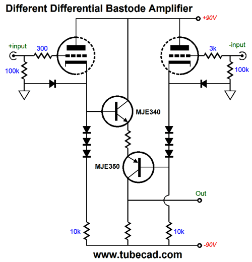
For more information on current mirrors and tubes, see post 245, post 246, and post 249. We can make a different differential amplifier that uses both an NPN and PNP transistor in a bastode configuration.
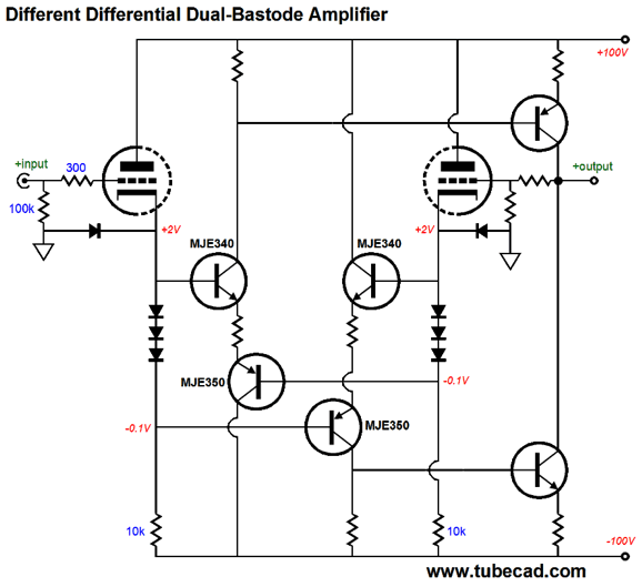
The output is in phase with the non-inverting input. The three diodes in series provide a fixed voltage drop and the strings can be shunted by a capacitor. Because this is a differential amplifier, the PSRR is quite good. We can double up on the bastode stages, as shown below
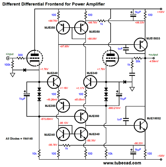
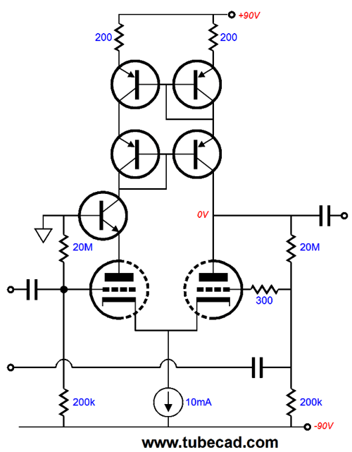
The Output is non-inverting. Now, fasten your seatbelt, as the following circuit might make fall off your chair.
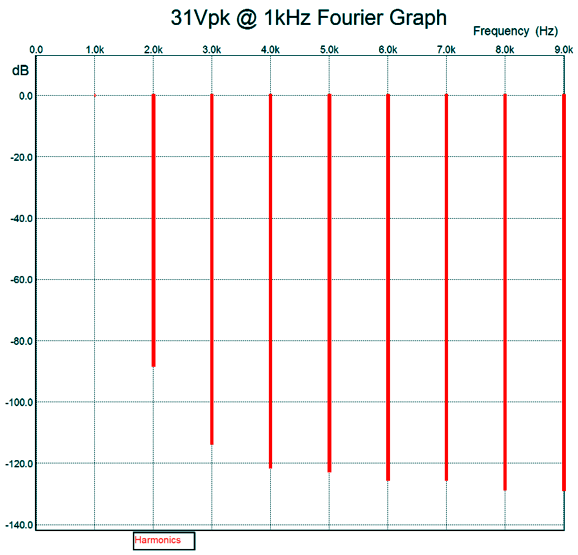
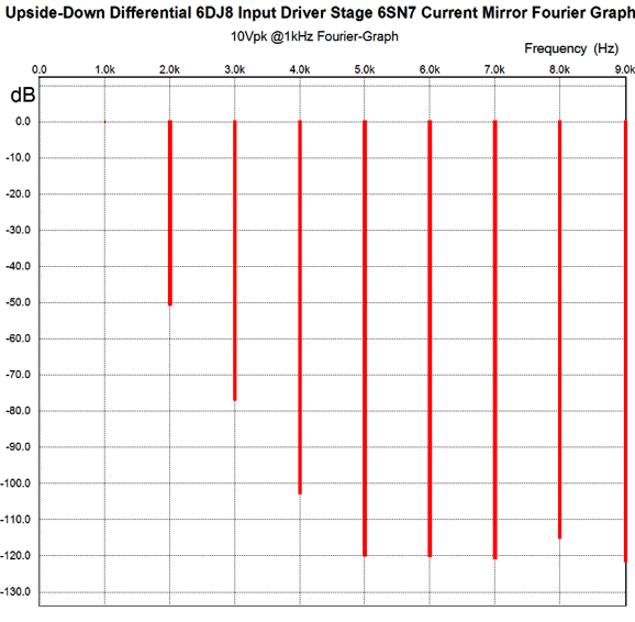
Yes, there is a lot going on here, so much so that it would take an entire post to just explicate it all—so, I won't. Think of it as homework for the advanced reader. By the way, in SPICE simulations, I used a 6DJ8 for the two triodes. Here is the Fourier graph.
Not bad. This translates into better than 0.01% of THD. Also note the wonderfully single-ended cascade of harmonics. The phase margin was about 90 degrees at the zero crossing. Now, imagine this circuit followed by a solid-state unity-gain, power-buffer output stage.
Practical Different-Differential Circuits
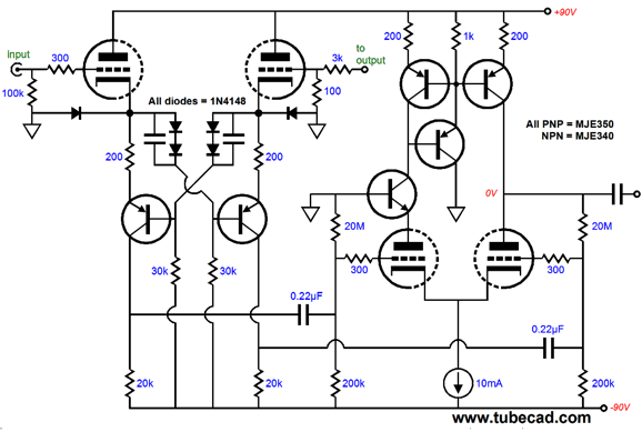
Note the capacitor bypassing of the diodes in series. Also note the DC negative feedback loop that centers the output at 0V. Alternatively, we can forgo the constant-current source and DC cross-couple the two bottom triodes, as shown below.
After some SPICE simulations, I discovered a leak. Not a real leak, but a loss of potential performance due to the resistors used to provide a current path through the diodes in series. Ideally, we want all AC current variations to flow through the 200-ohm cathode resistors and the PNP transistor collectors. One workaround is to replace these series resistors with constant-current sources.
Since we have hotrodded the input different differential stage, why not hotrod the conventional differential driver stage?
(Oops, I forgot to give the left triode its own grid-stopper resistor. The shame of it.)
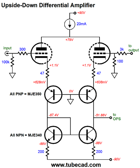
Different Differential Vs Upside-Down Differential
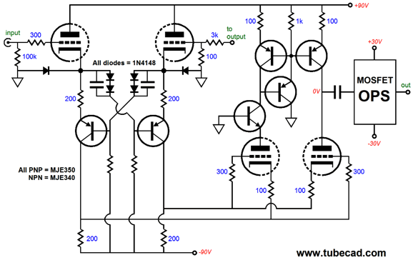
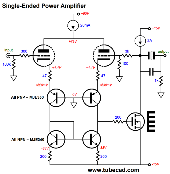
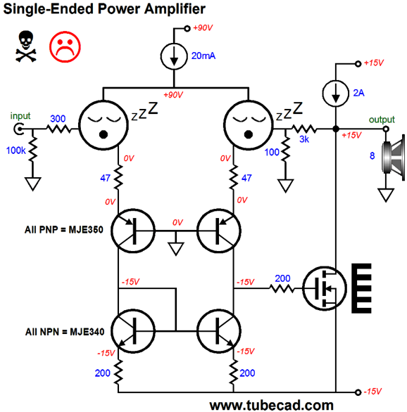
The output stage (OPS) could be as simple as a single power MOSFET.
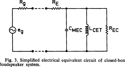
(This is the naked version. The fully-dressed version would include some extra capacitors to improve the phase margin.) Let's begin with the angry criticism provoked by the coupling capacitors. (Don't think I can't hear what some of you are thinking: "output coupling capacitors! Icky! This Broskie joker just doesn't get it") Where to start? First note the odd capacitor symbol; it denotes a non-polarized electrolytic capacitor. Panasonic happens to make superb non-polarized electrolytic capacitors. For an 8-ohm load to go down to 20Hz requires about 1kµF of capacitance, so we can place three 1kµF/16V non-polarized electrolytic capacitors in parallel with a 33µF film or PIO capacitor, which would take us down to 7Hz. Depending on your loudspeakers, a better way to go might be to purposely use a much smaller capacitor, say 330µF. Dear God, why? Alas, my technical library is still in disarray; thus, I could not find a super interesting paper on the bass effects of a series capacitor with an acoustic suspension speaker that was written by either Richard H. Small or Neville A. Thiele; nor could I find it on the web. I did find, however, the link to Small's paper on "Closed-Box Loudspeaker Systems Part I: Analysis." Inside which, we see this illustration:
If we place a capacitor in series, we will limit the low frequency response, true enough. But could also introduce a bass boost, as the coupling capacitor could provoke some peaking at the circuit resonance. An acoustic suspension speaker (a speaker driver housed in a sealed box) has a 2nd-order low-frequency roll off of -12dB per octave; adding a series capacitor will steepen the roll off to -18dB per octave (3rd-order), which will help to protect the driver from excessive excursions at low frequencies. If we jiggle the values correctly, we could end up with a speaker enclosure that provides flat bass down to 60Hz and then rolls off at 18dB per octave, which would prove excellent for a computer or small room. If you are still thinking Icky!, then think about what happens at startup, when the triodes are cold and not conducting.
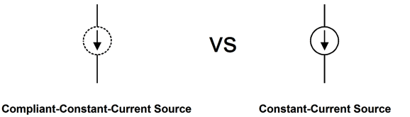
Not good. It is never good to deliver 15Vdc across your loudspeaker. What is the sound of one speaker burning up? I do not want to experience the answer. Do not think that you can use one of my compliant-constant-current sources (CCCS); you can't.
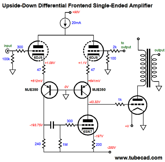
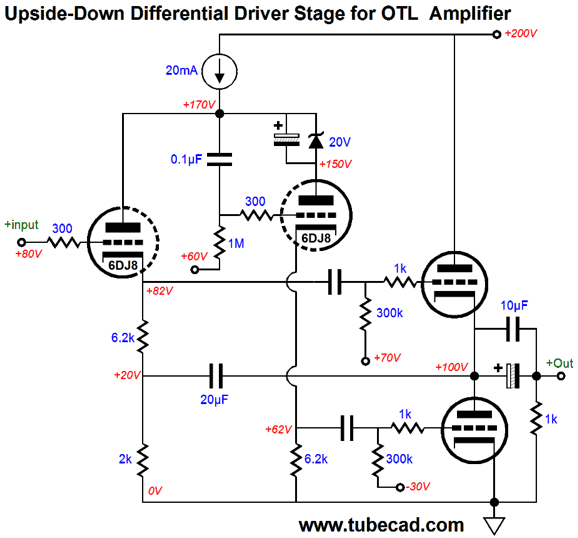
The CCCS would work if the MOSFET's idle current was pre-established; it's not. Indeed, I would use both a coupling capacitor and a shunting relay at the output. At startup, the relay would ground the speaker's positive terminal; then, when the amplifier stabilized, the relay would open and the music would pour forth. Another possible use for the upside-down differential amplifier stage is the following.
The 6SN7 triode defines a current mirror with the 240-ohm resistor. In SPICE simulations, the gain from the frontend was 166 (with balanced 1Vpk input signal; i.e. +1V & -1V) and the harmonic structure was a lovely single-ended cascade.
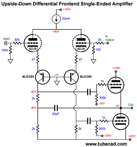
The output tube DC couples to the input stage, which can make setting the desired idle current difficult. The workaround would be to include a DC servo to maintain the output tube's desired idle current. Another possible use would be an OTL power amplifier.
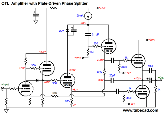
The 20µF capacitor establishes the needed balance between top and bottom output tubes, doing so by ensuring that both tubes function as grounded-cathode amplifiers. Don't see it? Imagine that an externally applied positive pulse delivered to the output. The bottom output triode will only see its plate voltage rise, so it can only offer its plate resistance to counter the pulse. The top output triode sees both its grid and cathode rise by the same amount, so it, too, can only offer its plate resistance to counter the pulse. In other words, the top triode does not function as a cathode follower. Since both triode function as gnd-K amplifiers, we must rely on the negative feedback loop to reduce distortion and output impedance. At startup, a relay can shunt the output to ground and then open when the output tubes have warmed up. More bells and whistles can and should be added, but the general layout is sound. We can lose the PNP transistors and use the plate-driven phase splitter to drive the output triode but not provide any signal gain.
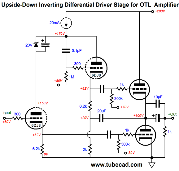
Note how the zener voltage matches the voltage dropped across the 2k resistor. If the resistor dropped 30V, we would use a 30V zener, as we wish to have both triodes experience and equal cathode-to-plate voltage. The above circuit preserves the input signal phase, which may not be what we need, so the following circuit would be used instead.
Note how the zener now appears on the left leg. Also note that the 2k resistor has moved to the right leg. This resistor terminates into ground, but it could terminate into an input triode's cathode, which would complete a negative feedback loop.
The input tube is not marked, as its type would depend what the intended load impedance will be. Headphone amplifiers have different requirements than power amplifiers do. For example, the above circuit would work with a 6DJ8 or 6N1P input tube and a 6H30 or ECC99 as output tube, if the amplifier was used to drive headphones. In contrast, if the load is 8-ohm speakers, then no input tube could provide enough gain; instead, a pentode or two triodes in cascode would be needed or two grounded-cathode amplifiers in cascade with the non-inverting version of the plate-driven phase splitter.
Next Time
//JRB
If you have been reading my posts, you know that my lifetime goal is reaching post number one thousand. I have 620 more to go. My second goal is to gather 1,000 patrons. I have 965 patrons to go. If I were a betting-man, I would place my bet on reaching the 1,000 patron goal first, as I have a hard time believing that I have already posted 380 times. How is that possible? I would never have bet on that happening. If you enjoyed reading this post from me, then you might consider becoming one of my patrons at Patreon.com.
Next Time
User Guides for GlassWare Software
For those of you who still have old computers running Windows XP (32-bit) or any other Windows 32-bit OS, I have setup the download availability of my old old standards: Tube CAD, SE Amp CAD, and Audio Gadgets. The downloads are at the GlassWare-Yahoo store and the price is only $9.95 for each program. http://glass-ware.stores.yahoo.net/adsoffromgla.html So many have asked that I had to do it. WARNING: THESE THREE PROGRAMS WILL NOT RUN UNDER VISTA 64-Bit or WINDOWS 7 & 8 or any other 64-bit OS. I do plan on remaking all of these programs into 64-bit versions, but it will be a huge ordeal, as programming requires vast chunks of noise-free time, something very rare with children running about. Ideally, I would love to come out with versions that run on iPads and Android-OS tablets.
//JRB
|
|
Kit User Guide PDFs
Only $12.95 TCJ My-Stock DB
Version 2 Improvements *User definable Download for www.glass-ware.com |
||


| www.tubecad.com Copyright © 1999-2017 GlassWare All Rights Reserved |