| John Broskie's Guide to Tube Circuit Analysis & Design |
15 April 2009
FFSR
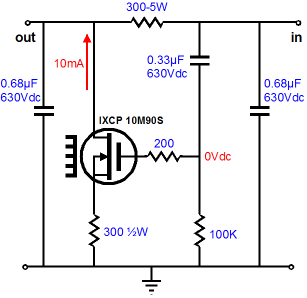
The circuit is simple enough: noisy B+ voltage goes in at the right and clean DC pours forth at the left. The power-supply noise was stripped away by the IXCP 10M90S constant-current source (a 900V depletion-mode MOSFET in disguise), as it increases and decreases its current conduction by the exact amount needed to counter the power-supply noise at its anode (the FFSR’s output). If its cathode resistor was 150 ohms, then the power-supply noise would remain, but inverted; if the cathode resistor was 600 ohms, only half the power-supply noise would make it through, but not inverted. By matching the cathode resistor to the series voltage-dropping resistor, we ensure a deep null in power-supply noise.
The photo above shows the new FFSR PCB. The boards are the same size as the H-PS-1 boards (2 by 4 inches) and the complete kit will cost the same, $24 USD (dirt, dirt cheap).
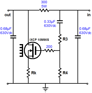
The actual schematic on the PCB is as follows.
The extra resistor, R3, allows us to vary the cathode resistor's value, while still using the same series resistor. For example, if a 100-ohm cathode resistor is used, resistors R3 and R4 must divide the incoming power-supply noise by three to achieve the same null at the FFSR’s output, as 300/100 equals 3. In this example, R3 must be twice as large as R4 to yield the 1/3 voltage division.
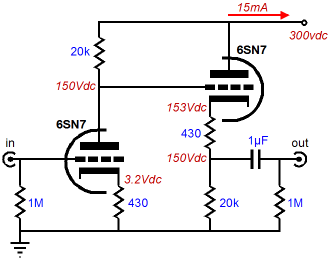
CCDA Circuit, Part Two
Additionally, since each circuit uses the same triode under the same cathode-to-plate voltage and idle current, the two cascading circuit deliver lower distortion than a single grounded-cathode amplifier could on its own. This is an amazing feat, as our expectation is for things to get worse with each subsequent electronic stage. The actual improvement is sight, but still altogether surprising and welcome. Moreover, the power supply, being greatly unburdened by the constant current draw, imparts fewer blemishes to the signal.
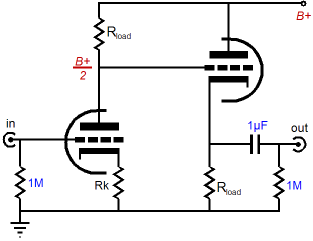
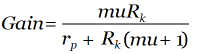
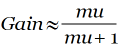
CCDA Reality Beginning with the first, won’t the external load impedance unbalance the matched load resistances? Yes, indeed, the external load impedance must be viewed as being in parallel with the cathode follower’s cathode resistor, so if a 47k load is placed in parallel with a 20k cathode resistor, the effective load resistance will equal 14k. So if the grounded-cathode amplifier must undergo a smaller current swing than the cathode follower, as Vo/20k is less than Vo/14k. The mistake here is to imagine that the cathode follower offers perfect unity gain; it doesn’t. Even when loaded by a constant-current source, a cathode follower will always delivers less than unity gain, as the following equation makes clear. Where Rk equals the cathode resistor independent of any external load. Now replace Rk with infinity, so that rp falls into insignificance and the gain reduces to approximately: In other words, although both the grounded-cathode amplifier’s plate resistor and the cathode follower’s cathode resistor can see the same DC voltage, they can never see the same voltage swings, as the cathode follower’s output will always fall a tad short. The end of the world? No, just the opposite. Returning to the previous example with the 47k input impedance presented by the power amplifier, the effective AC cathode follower cathode resistor value of 14k will force a greater current swing, which, with some good luck, can match the current swing shortfall from the cathode follower’s less-than-unity gain.
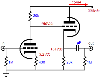
Let’s use a 6CG7/6SN7 triode as an example. With a cathode-to-plate voltage of 15oV and a cathode current of 7.5mA, a 6SN7 plate resistance is 8270 ohms; its mu, 21.5; and its gm, 2.6mA/V. Thus this triode, in a cathode follower circuit with an effective load resistance of 14k, will realize a gain of 0.93. So, if the grounded-cathode amplifier’s plate swings up 10Vpk, its current conduction will fall by 10/20k, or 0.5mA. The cathode follower’s cathode will swing up only 9.3Vpk and it s current conduction will increase by 9.3/14k, or 0.66mA. In other words, the two stages come close balancing each other out. Now, let’s sharpen the focus on reality once again.
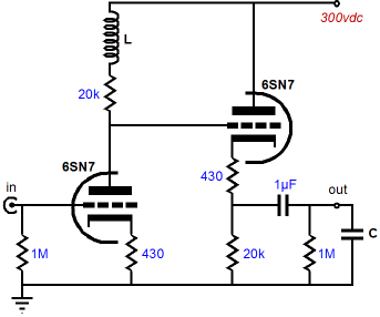
As the CCDA PCB is laid out, an additional cathode resistor can and should be used. This second cathode resistor should equal the cathode resistor used by the grounded-cathode amplifier stage; in this example, 430 ohms. This extra resistor helps to linearize the cathode follower’s transfer function and buffer the cathode follower’s cathode from heavy capacitance loads. In addition, this resistor will decrease the gain from the cathode follower. The math becomes a tad thicker now, but not by that much. The new effective load resistance becomes 14.43k and the gain at the cathode follower’s cathode is now 0.932 and the gain at the cathode follower’s output is 0.9, which will decrease the cathode follower’s current swing further. Although the two current swings will still not perfectly match each other, the net current swing will be much smaller than otherwise. Had the power amplifier presented a 100k input impedance, the match would be closer still. No doubt that you can guess that there is some optimal external load resistance that will ensure a perfect constant-current draw from the CCDA. The quick formula is to multiply the grounded-cathode amplifier’s plate resistor by the cathode follower’s gain. For example, if the cathode follower’s gain is 0.95 and if the plate resistor’s value is 10k, then the effective load resistance the cathode follower needs to see will be 9500 ohms, which will be made up from the cathode resistor in parallel with both the external load resistance and the 1M resistor that follows the coupling capacitor. This gets us close, but the cathode follower’s gain will change with the effective load resistance, so an iterative process is required to zero in on the right value. In addition the extra cathode resistor will define a two-resistor voltage divider with the bottom cathode resistor, so the math will need more massaging. My recommendation is to ignore the small imbalance, as the law of diminishing returns applies here. My rule of thumb with cathode followers is to always use a cathode resistor at least five times smaller than the external load. The next question requiring an answer is, what about heavily capacitive loads, such as long lengths of interconnect? True enough, cathode followers can stumble when driving large capacitances. The solution is more current, as charging and discharging capacitance quickly requires current. Slew rate against capacitance equals current, or I = SR x C. And slew rate equals 2πFVpk/1,000,000 (in microseconds). Thus we must first determine the amount of capacitance to be driven and the highest frequency and peak voltage swing expected. Ok, but what about the heavy capacitance load drawing more current at high frequencies, thereby throwing off the CCDA’s balance between first and seconds stages? A theoretical solution would be to place an inductance in series with the grounded-cathode amplifier’s plate resistor, as this would skew the grounded-cathode amplifier’s frequency response, increasing the high frequencies up until the mu of the triode is reached.
In other words, the frequency response would be flat up to some high frequency, then it will climb at +6dB per octave until the gain reaches the mu of the triode used, creating a shelving network. By placing an additional resistor in parallel with the inductor, we can shape the grounded-cathode amplifier’s high frequency boost to match any high frequency droop from the cathode follower into a capacitance load. Once again, I would ignore this solution—unless I planned on using the CCDA in a professional application wherein 500 meters of cable had to be driven or if I were designing an electrostatic headphone amplifier.
//JRB
|
E-mail from GlassWare Customers
High-quality, double-sided, extra thick, 2-oz traces, plated-through holes, dual sets of resistor pads and pads for two coupling capacitors. Stereo and mono, octal and 9-pin printed circuit boards available.  Aikido PCBs for as little as $24 http://glass-ware.stores.yahoo.net/
Support the Tube CAD Journal & get an extremely powerful push-pull tube-amplifier simulator for TCJ Push-Pull Calculator
TCJ PPC Version 2 Improvements Rebuilt simulation engine *User definable
Download or CD ROM For more information, please visit our Web site : To purchase, please visit our Yahoo Store:
|
|||


| www.tubecad.com Copyright © 1999-2009 GlassWare All Rights Reserved |