| John Broskie's Guide to Tube Circuit Analysis & Design |
27 May 2006 Hybrid Promise
It’s a division of labor that lets each device do what it does best. At least that’s the seductive promise. But can it be fulfilled? Remember, the two technologies work in series, not in parallel. Ask yourself which would taste best, wine from a bottle filled by a glass pipe or by a garden hose or by a glass pipe connected to a garden hose or from glass pipe and garden hose simultaneously? How much would it matter if the glass game first or the garden hose? Series is series. Here’s a metaphor: Imagine that a fierce debate whirled in telescope circles over glass lenses versus plastic lenses, with one group arguing that glass lenses revealed more and corrupted less than plastic lenses, which were said to rendered a plastic-like sheen to all that was viewed and induce headaches after an hour of gazing through them; while the other group claimed that plastic lenses were not only much cheaper, more modern, and durable than glass lenses, they were superior in that really large lenses could readily and cheaply be made from plastic, which would be impossible or obscenely expensive with heavy, brittle glass, which couldn’t be injection molded and had to be ground and which always held some slight tint that colored the view.
While this debate raged, 99.99% of lenses would be made from plastic. Yet, many ads in the telescope press would portray their plastic lenses as being as clear and as enjoyable to look through as glass; none would claim that their glass lenses viewed like plastic. Then one day, someone comes up with the idea of making a telescope whose small eyepiece was made from glass, but whose final large lens was made from plastic; the best of both worlds, the ads proclaim. But would it be? To switch metaphors one last time, would you still like the good cop, if all that he said to you had to be relayed through the bad cop? A little paranoia isn’t always bad and, in fact, it can be helpful. So are hybrid amplifiers always a bad idea? (In college, I had friend who divided the whole of existence with a guillotine-like slice into either great or garbage; there was nothing in between for him. Only the purest white; the purest black. Oddly enough, he was seldom happy.) Since I have listened to a few good-sounding hybrid power amplifiers and hybrid headphone amplifiers built on this premise, I know it is possible to make a wonderful-sounding hybrid amplifier for a fraction of the cost of an all-tube amplifier of comparable power output. Will it be perfect? I doubt that anything made by human hands can be perfect, but it might be quite enjoyable to listen to music through it.
Amplifier clipping In other words, we can feed the solid-state output stage the sweetest signal, but when the output stage clips, all our much-loved sweetness will be sawed off, leaving only a jagged end. At first it seems there are only two possible ways out: either build a solid-state output stage so powerful that it can never clip or turn down the volume so that clipping never occurs. Or is there a third way? What if we pre-clip the tube’s output signal before it reaches the solid-state output stage? In other words, what if we softly round off the peaks of the signal before the solid-state output stage relays it to our loudspeakers? In this way, the solid-state output stage would be faithfully passing on a softly distorted signal, rather than it sharply distorting a large pure signal. Sounds like a great idea, so where’s the catch? The catch lies in the sacrificed potential power output from the solid-state output stage. For example, a solid-state output stage that might have cleanly passed a 100W signal might only put out a maximum of 80W under this scheme. What—give up 20 watts!? Are you mad? Yes, I know that for many audiophiles this suggestion would be as welcome as penis-reduction surgery. Still, there is much merit to this idea: the ear can barely notice the difference between 80W and 100W, but it is supremely sensitive to the harsh harmonics generated by a clipped signal.
Soft-clipping circuit Rather than make the tube circuit softly clip, we can pre-clip its output passively. In the schematic below, we can see how the signal cleanly passes through a 10k resistor at low amplitudes, as none of the signal diodes are forward biases, but gets rounded off as the signal approaches the rail voltages, as the diodes start to conduct. 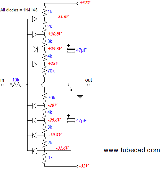 As long as the input signal falls within the +/- 28V window, it is passed without rounding. once it goes outside this window, the diodes become progressively conductive and the signal's peaks are rounded off. In the graph below, we see a SPICE generated graph of the above soft-clipping circuit under test. 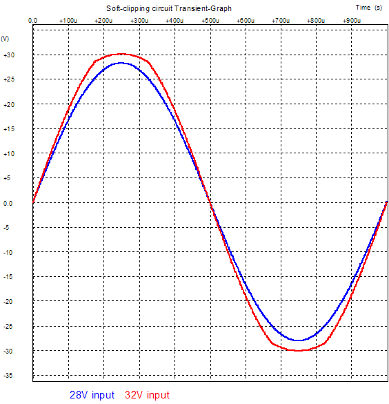
The blue trace is the result of a 28V input signal; the red trace, a 32V signal. Assuming that the unity-gain power buffer output stage could deliver a maximum of 30V of signal into an 8-ohm load, the output wattage would equal 56W. On the other hand, 28V of peak output signal equals only 49W. How important are those missing 7 watts of power? Not nearly as important as getting rid of the sharp clipping shown below from a 32V input signal. 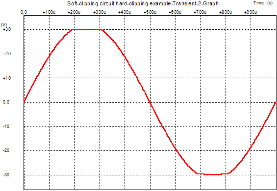
Next time //JRB |
 Aikido PCBs for as little as $24 WHAT IS AN AIKIDO AMPLIFIER?
The Aikido tube topology, created by John Broskie, delivers the sonic goods. Since the Aikido circuit came out in the Tube CAD Journal, people have been building it and marveling at its sound. A prediction: just as the 1980s were the cascode decade and the 1990s, the SRPP decade, this decade will be known as the Aikido decade. Why? This amplifier circuit offers voltage gain, low distortion, low output impedance, and a high PSRR figure—all without a global feedback loop. Better than SRPP Flexible Always Biases Up Correctly Functions Flawlessly No Popping Sounds at Startup, Less Distortion A Sound that’s Hard to Improve Upon AIKIDO AMPLIFIER PCB What makes them superior? First of all, they look fabulous and feel solid in the hand: extra thick (inserting and pulling tubes from their sockets won’t bend or break this board), double-sided, with 2oz copper traces, clean silkscreen and solder mask. (The board holds two sets of differently spaced solder pads for each resistor, so that radial and axial resistors can be easily used. Each capacitor finds several solder pads, so wildly differing sized coupling capacitors can neatly be placed on the board.) Each board holds two Aikido linestage amplifiers; so, one board for stereo unbalanced or one board for one channel of balanced amplification. The boards hold two coupling capacitors, each finding its own 1M resistor to ground. The idea here is that you can select (via a rotary switch) between C1 or C2 or both capacitors in parallel. Why? One coupling capacitor can be Teflon and the other oil, or polypropylene or wax and paper…. As they used to sing in a candy bar commercial: “Sometimes you feel like a nut; sometimes you don't.” each type of capacitor has its virtues and failings. So, use one type of coupling capacitors for old Frank Sinatra recordings and the other for string quartets. Or the same flavor capacitor can fill both spots: one capacitor would set a low-frequency cutoff of 80Hz for background or late night listening; the other capacitor, 5Hz for full range listening. Or if you have found the perfect type of coupling capacitor, the two capacitors could be hardwired together on the PCB, one acting as a bypass capacitor for the other. The board assumes that a DC 12V power supply will be used for the heaters, so that 6.3V heater tubes (like the 6SL7 and 6SN7) or 12.6V tubes (like the 12SL7 or 12SN7) can be used, for example on an octal board. Both types can be used exclusively, or simultaneously; for example 12SX7 for the input tube and a 6BX7 for the output tube. (A 6V heater power supply can be used, as long as all the tubes used have 6.3V heaters; and an AC heater power supply can be used, if the heater shunting capacitors are left off the board.) The boards are four inches by ten inches, with eight mounting holes. Boards are made in the USA and come with instructions that include schematic and recommended part values. A real E-mail from a new Aikido PCB owner:
Visit our Yahoo Store for more details: | |||


| www.tubecad.com Copyright © 1999-2006 GlassWare All Rights Reserved |