| John Broskie's Guide to Tube Circuit Analysis & Design |
|
Post 245 03 October 2012
Cathode-Coupled Circuits 1999/tubecircuits/Common-Cathode Amplifiers Well, can there be any blood left for me to wring from this old rock? Sure. For example, the following cathode-coupled amplifier circuit holds only a single capacitor, yet offers amazing performance, such as very-low distortion and stellar PSRR.
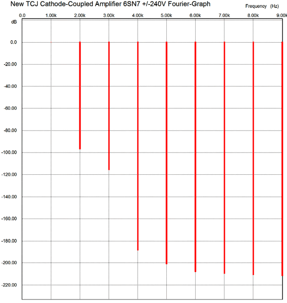
The assumption behind the circuit is that the bipolar power supply holds equal, but out-of-phase ripple on each rail. This is usually the case, but carelessness can undo the symmetry, such as loading one rail more than the other. So, assuming that the two power-supply rails mirror each other, the above circuit works several behind-the-scenes tricks that result in an amazing PSRR figure. First of all, note how no constant-current source is used to load the differential input stage; instead, two 12k cathode resistors in series are used as a long tail. The 24k of resistance, while quite large, will not result in a constant-current draw, as the negative rail’s power-supply noise will impose a noise current equal to Vnoise/24k. This ripple-induced current must flow equally through the two input triodes. Thus, the 20k plate resistor will see ripple voltage superimposed by the ripple current. In addition, this plate resistor attaches to the positive power-supply rail, which holds its own out-of-phase ripple to the negative rail. The result is that about half of the positive power-supply rail ripple appears at the differential amplifier stage’s output. This output signal must then travel through the 66% voltage divider made up of the three 120k resistors. Since this resistor string terminates not into ground , but the negative power-supply rail, a null in ripple occurs where cathode follower’s grid attaches to the voltage divider. The cathode follower also rejects the power-supply noise, as the triode and the 845-ohm cathode resistor create a 30k resistance that matches the the two 15k cathode resistors, so a null appears at the output. In other words, we throw away 33% of the audio signal so that we can throw away all of the power-supply noise. The two diodes are merely protection devices that cease conducting once the tubes heat up, causing the diodes to be reverse biased. The 1.1k resistor is needed to compensate for the input triode seeing twice the cathode-to-plate voltage than its partner. The gain is about 4 (+12dB) and the output impedance is about 1,000 ohms, which isn’t too shabby. The PSRR comes in at better than -40dB (if the cathode follower's 845-ohm resistor is replaced by a 1k resistor, the PSRR improves by even more). The distortion is embarrassingly low, at least in SPICE simulations. Here is the Fourier graph for 1Vpk @ 1kHz into 47K load.
Cathode-Coupled OpAmp
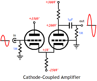
Before revealing its flaw, I will describe its operation. Its inspiration was a single-ended power amplifier design I created long ago and that displayed back in 2001.
(Very retro image, no? I still like the gray backgrounds, but I dislike the GIF's graininess.) In the above amplifier, the triode in the middle completes a feedback loop by relaying the output tube's plate swings down to its cathode, which is coupled to the input triode's cathode. No capacitor is needed and it makes good use of the dual-triode tube's second triode. (Mind you, this triode will see all the huge plate swings that the output tube undergoes.) The next step in translating this SE amplifier into the cathode-coupled OpAmp circuit is to replace the output transformer with a simple plate resistor.
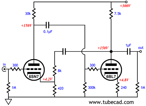
If you do not see how the 6SN7 triode that attaches to the 6BL7's plate defines a feedback loop, substitute the triode with a resistor (and capacitor).
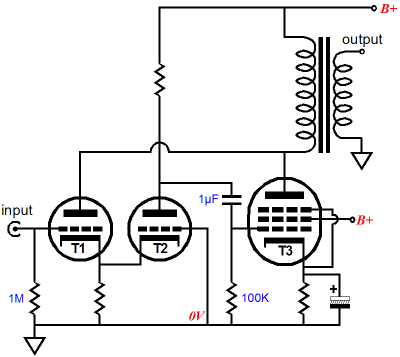
A 6SN7's plate resistance is about 8k, so an 8k NFB resistor is shown. I know that many readers are instantly getting that the triode's mu will set the gain of this line-stage amplifier—and they are right. The only problem with variation is that the internal capacitor must be large in value, so as to preclude the phase shifts it introduces from causing problems. The triode-as-NFB-resistor approach side steps the capacitor problem. In addition, the triode not nearly as linear as the resistor, but its curvature complements that of the input tube, resulting in a more linear combined transfer curve. As I look at it now, it being the schematic above the one above, I am reminded of A. J. van Doorn's Octode circuit:
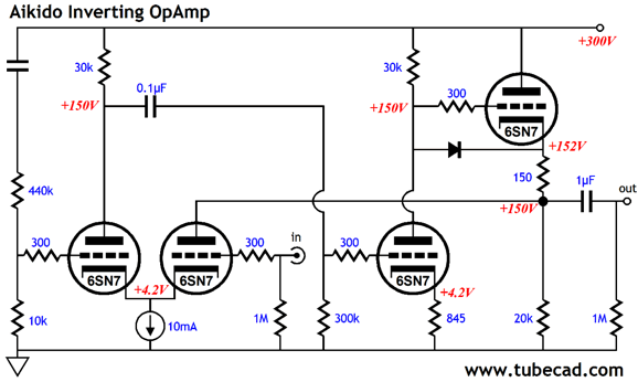
The difference being with triode is used as the input tube. By the way, the octode circuit also comprises a hidden negative feedback loop: triode T1's plate. To see how it functions, just imagine a positive voltage pulse applied to the secondary, say a D-cell battery momentarily making contact with the speaker terminals. This pulse will reflect itself upon the primary, causing T3's plate voltage to bounce upwards in voltage, which, in turn, will cause T1's plate to also bounce upwards, provoking a greater current conduction from T1, resulting in a small positive pulse appearing at its cathode, which forces T2 to conduct a tad less, making T2's plate voltage climb, which T3's grid sees as a positive voltage pulse, compelling T3 to increase its current conduction, pulling its plate downward, bucking the externally applied pulse. Feedback, in other words. Well, its time to reveal the flaw of the original cathode-coupled OpAmp circuit: its PSRR is only -6dB; worse, the B+ ripple is inverted at the output. Why is that a tragedy? If the ripple had been in phase, then the only solution is to use a better power supply. But with inverted ripple, we had the chance to null the ripple at the output, but failed to realize it. As I saw it, some magic ratio of gain between triodes would result in a deep null of the power-supply noise. But I never pursued this goal. Well, after reexamining the circuit, I saw how I could apply an Aikido move that would compel the noise null. The first step is to use the other differential triode as the input tube. Next, inject a fixed portion of power-supply noise into the input stage. Very Aikido.
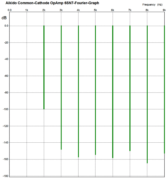
This amplifier inverts the input signal at its output, which may or may not be a big deal. It does offer a PSSR of about -6odB and Zo of only 60 ohms. The gain comes in at 18 (+25dB), which seems a little too hot to me, but some do need the extra gain. The distortion is very low indeed, as the following SPICE simulation's Fourier graph shows.
Of course, individual mileage may vary. Nonetheless, this is an interesting topology.
Current Mirror & Cathode-Coupled Amplifiers
Most tube-loving folk do not know what a current mirror is. This is a mistake, as current mirrors are simple and interesting topologies.
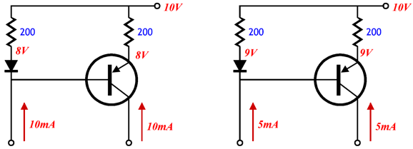
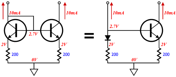
The function is simple enough: the amount of current flowing through the left branch is matched by the right branch. If 10mA are drawn on the left, then 10mA will be drawn on the right; 5mA on the left, 5mA on the right. Easy enough. Where most neophytes get lost is when the diode is substituted by another transistor, as shown below on the left.
Whoa! My brain just shut down! Reboot and look at the voltage relationships between these two current mirrors. They are the same, which makes perfect sense, as the PNP transistor with its base attached to its collector is functionally a diode. While we are at it, I should point out that current mirrors can also be made out of two NPN transistors or one diode & an NPN transistor.
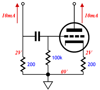
Indeed, current mirrors can also be made out of triodes.
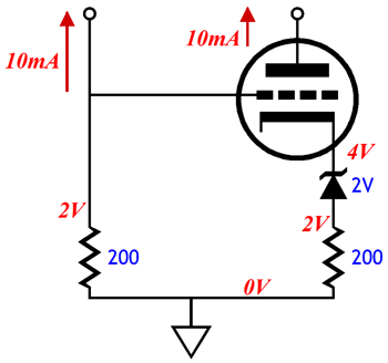
The above current mirror is an AC current mirror, but a DC tube-based current mirror can be made with a voltage reference.
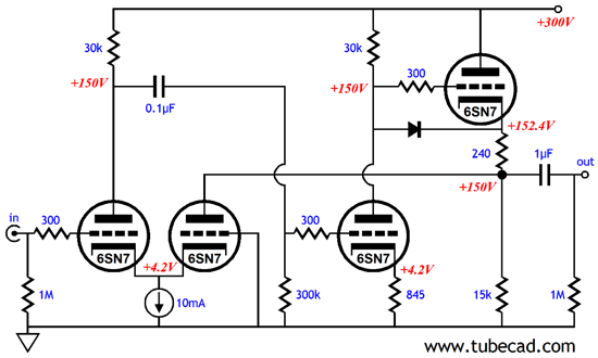
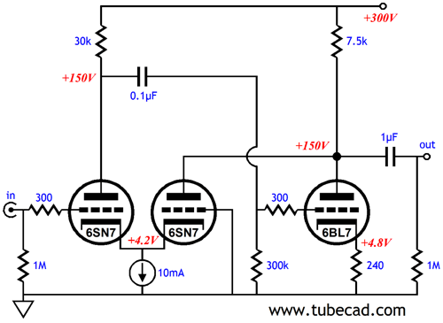
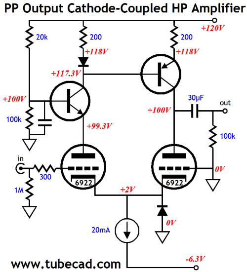
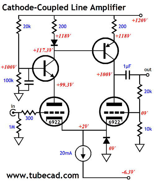
Okay, now that we are all up to speed on current mirrors, let's get back to tube circuits. The following circuit is certainly an eyeful, but not difficult to understand.
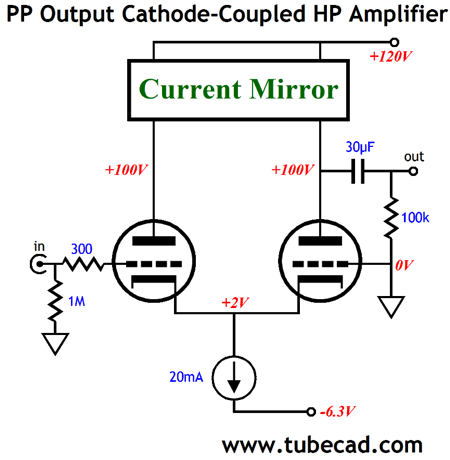
The current mirror is there, so what is the NPN transistor doing there? It serves two purposes: it acts as a capacitance-multiplier circuit, which delivers a ripple-free DC plate voltage for the input triode, while still letting the triode's current to flow up to the current mirror; second, it sets the input triode's plate voltage to 99.3V not 117.3V, which in turn will set the output triode's plate voltage to roughly the same voltage, which is necessary to give the output tube room to swing its plate up and down. The diode at the bottom is there as a safety device, although with only a -6.3Vdc negative power-supply rail, it may not be needed. A 20mA constant-current source sets the idle current. So how does this circuit push and pull? Imagine a negative input voltage great enough to turn off the input triode. The 20mA constant-current source will continue to conduct, but its only current path to the B+ connection is through the output triode, which will conduct much more readily, as its grid has been effectively made much more positive relative to its cathode. At the same time, the current mirror will reflect the zero current conduction by the input triode. Thus, the only current path available is through the external load, the 300-ohm headphone impedance. This is how the circuit pulls down. To see how it pulls up, imagine a positive input voltage large enough to make the input triode's cathode sufficiently positive to turn off the output triode. The 20mA will now flow through the input triode, which means that the current mirror will reflect the 20mA flow. But as the output triode is turned off, the current mirror will pull up the output voltage by flowing into the load resistance. The gain of the circuit is about 3 (+9.5dB), with a 300-ohm load. The output impedance is about 2,800 ohms—the tube's rp, in other words. Thus, this amplifier can be viewed as being closer to a current-out amplifier, rather than a voltage-amplifier. The distortion is less than 0.1% at 1Vpk into 300-ohms @ 1kHz in SPICE simulations, rising to about 1% at 3Vpk. The PSRR figure is an excellent -52dB. Used as a line amplifier, this circuit still delivers a clean output.
The above feedback resistors set a fixed gain of about 3 and lower the Zo to about 250 ohms.
Next Time
//JRB
|
|
I know that some readers wish to avoid Patreon, so here is a PayPal button instead. Thanks.
John Broskie
E-mail from GlassWare customers:
And
High-quality, double-sided, extra thick, 2-oz traces, plated-through holes, dual sets of resistor pads and pads for two coupling capacitors. Stereo and mono, octal and 9-pin printed circuit boards available.  Aikido PCBs for as little as $20.40 http://glass-ware.stores.yahoo.net/ Only $12.95 TCJ My-Stock DB
Version 2 Improvements *User definable Download or CD ROM www.glass-ware.com |
||


| www.tubecad.com Copyright © 1999-2012 GlassWare All Rights Reserved |