| John Broskie's Guide to Tube Circuit Analysis & Design |
|
04 February 2017 Post 371 I am getting so close to post 400 that I can taste it. Just 29 to go to hit number 400; 629 to go to hit Post 1000.
Balanced Cathode Followers
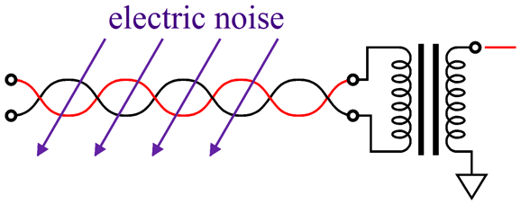
CMRR is a key feature of balanced-audio setups. In a high-CMRR system, a signal held in common, equal in amplitude and in phase, delivered to both inputs of a balanced amplifier is ignored, while differential signals are passed. Why is this a feature? A good example of a common-mode signal is noise, either resulting from the power-supply ripple in the signal source electronics or induced by an electrically noisy environment. For example, an isolation transformer is an intrinsically balanced device, as it rejects any signal common to both the primary's leads.
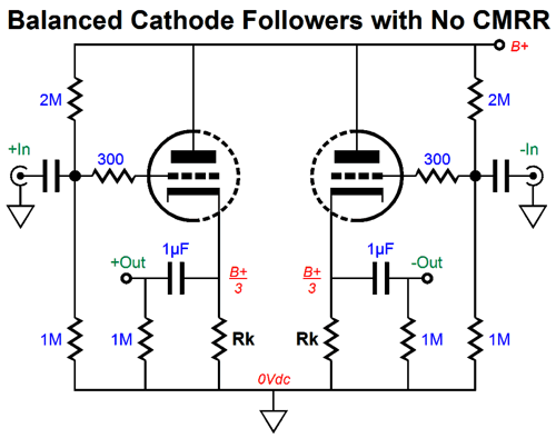
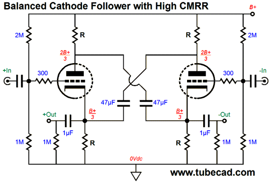
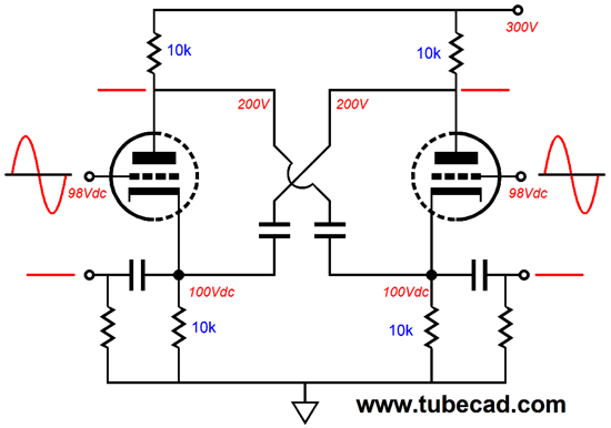
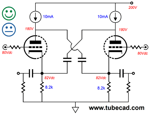
The two cathode followers shown above, however, work entirely independently from each other. If both are given the exact same signal, they both will happily pass that signal out at their cathodes. Zero CMRR, in other words. In contrast, The circuit below exhibits a high CMRR, as a signal common to both inputs is largely ignored at the two outputs.
How is this feat of magic achieved? The large 47µF capacitors tightly cross-couple cathodes to plates. When presented with a pair of balanced input signals, equal in amplitude, but opposite in phase, both triodes work in unison but in anti-phase current conduction, so as one triode's conduction increases, the other's decreases.
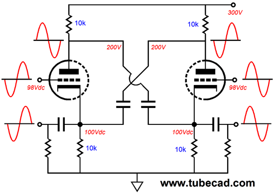
Should both inputs see a positive input signal, the two triodes cannot easily increase their current conduction in unison, thereby pulling up both cathodes, as any effort to pull up both cathodes at once would be stymied the 47µF capacitors. Without the large cross-coupled capacitors, an increase in current flow through both cathode resistors would be matched an increase in current flow through both plate resistors, something that the large-valued capacitors oppose. In order for one cathode to move up in voltage the cross-coupled plate must also move up in voltage; in order for one cathode to move down in voltage the cross-coupled plate must also move down in voltage. The result is a tie, with neither cathodes nor plates moving. The two triodes' current conduction may go up or down in unison, but to no effect, as the capacitors act like batteries and supply the needed current. I was about to write that it is like pressing down on both the gas peddle and brake, but a better analogy would be throwing the car into first-gear and reverse at once.
Just how good is the CMRR? It depends on how big the two large-valued capacitors are in value. With 10µF the CMRR came in at -22dB in SPICE simulations; with 47µF, -36dB; and with 470µF, -56dB. In other words, the bigger the large-valued capacitors are, the better the CMRR.
I covered this topology a few times before, the last time being in post 317, which is worth reading in spite of the topic being Circlotrons. (Indeed, it is well worth reading due to its amazingly silly but impressive first paragraph. I had forgotten that I had written it and I got a good chuckle from reading it just now. And the penultimate sentence says it all.) The balanced cathode follower—or crisscrossed cathode follower or cross-coupled cathode follower, as I might have labeled it before—is basically a Circlotron that uses big capacitors instead of floating power supplies.
Like the Circlotron that uses floating power supplies, the balanced cathode follower can be run in class-A or class-AB. Unlike the Circlotron that uses floating power supplies, the balanced cathode follower cannot be run in class-AB continuously, as the large-valued capacitors will eventually discharge. In contrast, the reservoir capacitors in the Circlotron, which uses floating power supplies, are being continually recharged by the wall voltage. Is this a big deal? It depends. If you listen to big sustained sinewaves, you are in trouble. If you listen to sufficiently interesting music to provide a wide dynamic range, with occasional crescendos, then you are in luck. Indeed, I am amazed by how well the balanced cathode follower works in the face of huge tone bursts. The first time I built this circuit was over 20 years ago. I used a 300-ohm load resistance across the balanced outputs and I used a 6DJ8 tube with 10mA flowing through each triode. The class-A window of operation would thus be limited to peaks of +/-20mA of current flow into the 300-ohm load. Nonetheless, I got clean peaks of almost 50mA! This means that with ten 6DJ8 tubes per channel, we could get 1W into 8-ohm speakers. Okay, John, sure the high CMRR is a fine feature, as is big peak current flows, but what about output impedance? Isn't that what a cathode follower all about? The output impedance is equal rp/(mu + 2), just the same as the Circlotron. With a 6DJ8, that means about 90 ohms differentially or 45 ohms from each output relative to ground. What about PSRR? If the output is taken differentially, say by a headphone's driver element, then the PSRR is off the charts, because of the differential cheat. Cheat? Think about it: place both leads of a headphone element across a super-noisy B+ connection (DO NOT do this in reality, only your imagination) and listen for noise. You wont hear any, as the driver sees no differential signal, so it remains still. At the B+ connection, the PSRR is zero, yet you hear no ripple or hum from the headphone. Relative to ground, however, the PSRR is dismal -6dB. This is hardwired into the topology, much like the audiophile-vouchsafed assertion that the Circlotron must always and only operate in class-A, except that this time it's true. To see why this must be so, imagine the two large-valued capacitors replaced by dead shorts; then, as long as the plate and cathode resistors all share the same value, 50% of the power-supply noise must leak out the outputs, as we have created a 50% voltage divider. Of course, if we make the plate resistors three times larger in value than the cathode resistors, we will define a 25% voltage divider that would yield a PSRR figure of -12dB. Well then, why don't we get clever and replace these four resistors with constant-current sources? Not a good idea, alas.
It is never a good idea to place two constant-current sources in series with each other, as a tug o' war in which both sides end up losing, the circuit bouncing away as giant flip-flop. Placing a triode in series with the two constant-current sources does not stop them from being in series with each other. On the other hand, replacing just the plate resistors does offer some real advantages, such as shielding the cathode followers from the power-supply noise.
One problem we are likely to encounter is that the constant-current sources may not settle where we think they should. Why not? They are working into a very high impedance, as the effective plate resistance in the above example is equal to rp + (mu + 1)Rk. With a 6DJ8 triode, the impedance comes in at about 280k. Constant-current sources are much happier terminating into low-impedance terminals, such as a cathode or emitter. The better solution is to use compliant-constant-current sources (CCCS) instead. Here is a quote from post number 290, which nicely describes what a CCCS is.
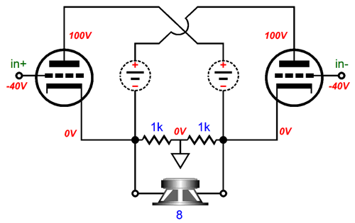
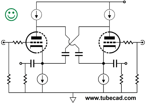
Note the dashed lines on the compliant-constant-current sources (CCCS) symbol. Solid lines equal CCS; dashed lines, CCCS. The two CCCS set a fixed DC plate voltage at idle, but allow big plate voltages swings under use. Here is one possible implementation.
The two MOSFETs set the fixed DC plate voltage at idle and yet swing up and down with the output signal and present a truly high impedance, in spite of looking like source followers. Another possibility is to replace the cathode resistors with constant-current sources.
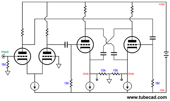
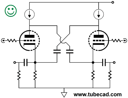
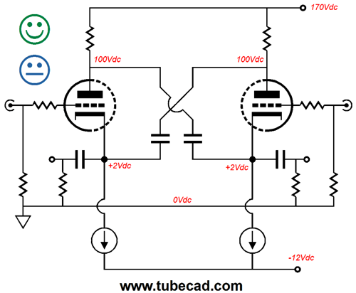
If the B+ voltage is high enough (and the triode's mu low enough), we can forgo the input coupling capacitors and the grid-biasing network, as we can DC couple the inputs at ground level. If the B+ voltage is not high enough (or the triode's mu too high), we can use a low-voltage negative power-supply rail, as shown below.
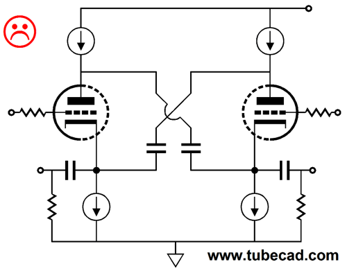
Why the undecided face? If the outputs are taken relative to ground, the 0dB PSRR will be a problem; but if the outputs are taken differentially, with no regard to ground, then the nonexistent PSRR will prove a non-issue. The best-case scenario is where the plates see two compliant-constant-current sources, while the cathode see two constant-current sources. Now we have superb PSRR and fixed operating voltages.
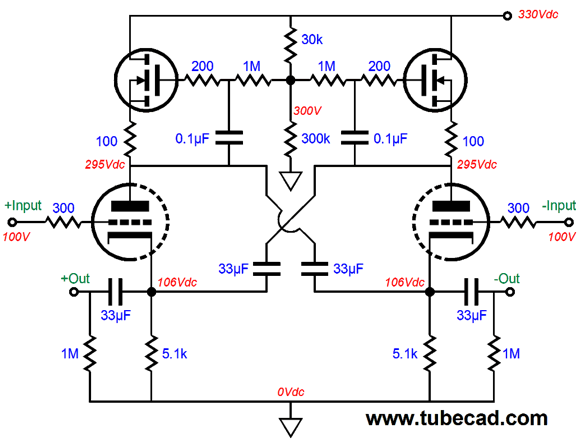
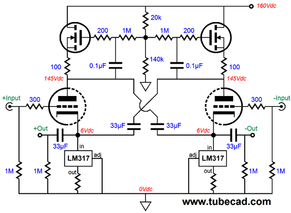
Making the above schematic work in reality might look like the following design.
The assumption was that 300-ohm headphone elements were the intended target loads; thus, the large 33µF coupling capacitors. The additional assumption was that a beefy tube, such as the 6H30 or 5687 or ECC99, is used and that an idle current greater than 10mA flows through each triode. If balanced line-stage use is the real intention, then much smaller output capacitors could be used, say just 1µF. On the hand, if an expected input impedance of 600-ohms is the target, then 20µF capacitors are a better choice.
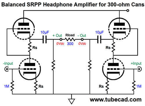
Balanced SRPP Output
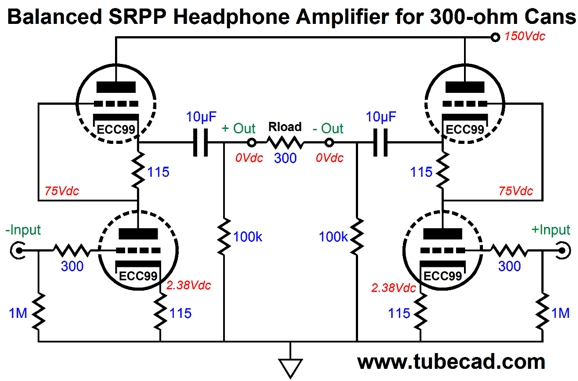
Note the seemingly too small coupling capacitors in the above schematic. Because the two SRPPs present such a high differential output impedance, about the triode's rp from output to output, the small coupling capacitors can still pass the desired low frequencies. In SPICE simulations, the 10F capacitors yielded a -3dB frequency of 13Hz. Here is a flesh-out design example.
The 115-ohm cathode and current-sense resistors may seem too low in value, according to the famous SRPP formula of Rs = (rp + 2Rload) / mu but effectively each SRPP is working into a 150-ohm load, not a 300-ohm one.
Next Time
//JRB
If you have been reading my posts, you know that my lifetime goal is reaching post number one thousand. I have 629 more to go. My second goal is to gather 1,000 patrons. I have 970 patrons to go. If I were a betting-man, I would place my bet on reaching the 1,000 patron goal first, as I have a hard time believing that I have already posted 371 times. How is that possible? I would never have bet on that happening. If you enjoyed reading this post from me, then you might consider becoming one of my patrons at Patreon.com.
Next Time
User Guides for GlassWare Software
For those of you who still have old computers running Windows XP (32-bit) or any other Windows 32-bit OS, I have setup the download availability of my old old standards: Tube CAD, SE Amp CAD, and Audio Gadgets. The downloads are at the GlassWare-Yahoo store and the price is only $9.95 for each program. http://glass-ware.stores.yahoo.net/adsoffromgla.html So many have asked that I had to do it. WARNING: THESE THREE PROGRAMS WILL NOT RUN UNDER VISTA 64-Bit or WINDOWS 7 & 8 or any other 64-bit OS. I do plan on remaking all of these programs into 64-bit versions, but it will be a huge ordeal, as programming requires vast chunks of noise-free time, something very rare with children running about. Ideally, I would love to come out with versions that run on iPads and Android-OS tablets.
//JRB
|
|
Kit User Guide PDFs
Only $12.95 TCJ My-Stock DB
Version 2 Improvements *User definable Download for www.glass-ware.com |
||


| www.tubecad.com Copyright © 1999-2017 GlassWare All Rights Reserved |