| John Broskie's Guide to Tube Circuit Analysis & Design |
| 16 March 2014
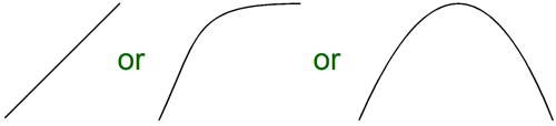
Class-A Wizardry In electronics, "class-A" is not honor bestowed, but an account of an amplifier's mode of operation. It describes a dynamic process, wherein the output devices continue to conduct current in a meaningful way throughout the amplifier's peak output waveform. By way of a fortunate happenstance, when the two opposing output devices in a push-pull amplifier continually conduct over the entire output waveform, the distortion and output impedance falls. This pleases the ear. Just as our hand prefers to rub across smooth polished marble without encountering scratches or bumps, our ear prefers not to confront sonic discontinuities in a sound wave. Class-B power amplifiers present a scratch-like notch where the waveform switches polarity and neither output device conducts. In contrast, class-AB amplifiers display two transitional drops, one above and one below the center of the waveform, the points where either output device cuts off, creating a sonic bump; the area of conduction overlap is called as gm-doubling. In a class-A, push-pull output stage, the area of gm-doubling covers the entire waveform, saving the ear from the two transition points. But a power amplifier's sonic signature is not entirely dependent on its output stage, as much can go wrong in the input and driver stages. Nonetheless, running a push-pull output stage in rich class-A mode is a fairly safe bet for improving the amplifier's sound. When I in was college, I was adjusting the idle current on my solid-state power amplifier and I found the that the higher bias the better the sound, a simple linear relationship. Few things are linear. So, I wondered if instead of a straight line of sonic improvement, maybe the line was a curve, which might climb and then flatten horizontally or, worse, might reach a peak and then decline.
I decided that I needed to do some dynamic testing. I bought a long shielded extension cord with three internal wires. I then wired up plug end inside my amplifier to its bias circuit; at the socket end, I attached a potentiometer. I then sat down and listened away to mono LPs, while adjusting the idle current from afar. The higher the idle current the better the sound—seemingly a straight line all the way up to smoke and burnt output transistors. Since that day, I have performed many more experiments and I have found that in some cases, a thin idle current created a more dynamic sound, rough but exciting; and a fat idle current, a smoother, more refined but overly damped sound. (The transistor failing of beta droop must also be factored in our reasoning.) Thus, strict logic and plain honesty demands that we acknowledge that not all superior power amplifiers operate in class-A and not all class-A power amplifiers are superior. Yes, indeed, I have heard some bad-sounding class-A power amplifiers. For example, all single-ended amplifiers run in class-A, there being but a single output device after all, but not all single-ended amplifiers are superior, alas.
Power-Boosted Class-A Amplifiers
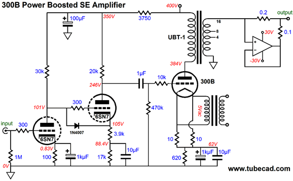
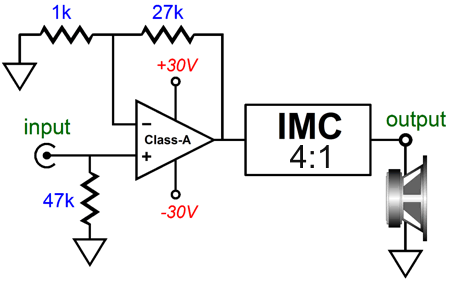
As far as the 300B was concerned, it was working into a 2400-ohm load; as far as the output transformer's secondary was concerned, its secondary was working into 32-ohms. Thus the output transformer's winding ratio needed to be 10:1, as the square root of 2400/24 is 10. The UBT-1 single-ended output transformer holds a 14.14:1 winding ratio between its primary and the 8-ohm tap on its secondary; and, a 10:1 ratio on its 16-ohm tap. In addition, this fine output transformer can easily put out 12W. That was a quick recap. Now, let's look at the 32-ohm the IMC presents to the secondary. Headphones often sport a 32-ohm impedance, but no loudspeakers are sold with such a high impedance. This is something of a pity, as a 32-ohm impedance is much more tube-friendly. Tube-based OTL power amplifiers strain to deliver their current into 8-ohm loudspeakers, whereas a 32-ohm load would be four times easier. Remember, most tube amplifiers are current limited, while most transistor-based power amplifiers are voltage limited. Thus, just as a tube-based OTL power amplifier can deliver more power into a higher impedance load, transistor-based power amplifier can deliver more power into lower impedance loads. But what if we are more concerned with distortion than with power, which impedance would produce less distortion? The answer is that both amplifier types would deliver less distortion with a higher impedance load. An additional point to remember is that when it comes to push-pull power amplifiers, it makes little sense to speak of the amplifier's class of operation, without first specifying the load impedance and a power output. For example, all audio push-pull power amplifiers run in class-A, if the load impedance is 10k. And even the lowly class-AB power amplifier within a cheap receiver runs in class-A for a small portion of its power output, with an 8-ohm load. For example, if the transistor-based power amplifier runs an output stage idle current of 100mA, then it can swing up to +/-200mA of current before leaving class-A operation and entering class-AB. How much power does that translate into with an 8-ohm load? Not much, only 0.16W (or ad the ad copy writer would put "a big 160 mW"). It would, however, equal 1W into a 50-ohm load, but with 10Vpk output voltage swing, not the 1.6Vpk into 8 ohms. In contrast, 200mA peak into a 4-ohm load causes the wattage to fall to 0.08W. In other words, one way to extend the window of class-A operation is to drive a higher impedance load. This brings us back to 32 ohms. If a power amplifier can swing +/-32Vpk into an 8-ohm load, then the speaker will see 64W; with 4-ohm speakers, 128W. And if the same power amplifier drove a 32-ohm speaker, the speaker would see 16W of power. The next question is, How high would the push-pull power amplifier's idle current need to be to ensure class-A operation for the full 16W into the 32-ohm load? The answer is that the idle current must at least equal half of the peak current flow into the load. In this example, 1A peak, as 32V dived by 8 ohms equals 1A, so the amplifier's output stage must at least idle at 500mA. Now, 500mA may not sound like a lot of current, compared to what a class-A power amplifier that works into 8-ohm load must idle at, but it is about ten times more than most transistor-based power amplifier run their output stage under. As I put it back in issue Number 9 of the Tube CAD Journal:
In a single-ended amplifier, the tug of war still obtains: the single output device fights agains the output transfomer's primary inductance, which opposes a change in current flow by definition. Still, building a high-quality, class-A power amplifier that works into 32-ohm load is about four times easier than building one for an 8-ohm load, as many fewer output devices along with a smaller power transformer and heatsink will be needed. Sure, but what good would a high-quality, class-A power amplifier that works into 32-ohm load be, if you cannot buy a high-quality 32-ohm loudspeaker? My answer, obviously enough, is that an impedance multiplier circuit can make your existing 8- or 4-ohm loudspeakers appear as a 32-ohm load to such an amplifier.
In other words, we could build a stellar solid-state power amplifier that could take the place of the 300B-based power amplifier, as the impedance multiplier circuit doesn't care where its input signal comes from. The high-quality solid-state amplifier would deliver both the IMC's input signal and provide a quarter of the output power that the loudspeaker sees. But wouldn't designing a high-quality, solid-state, class-A power amplifier that drives 32-ohm loads be difficult to design? Yes, it would, but then all high-quality power amplifiers are difficult to design. But you don't have to the do design work, as many gifted amplifier designers have already done the hard work for you. For example, John Linsley Hood designed a fun little class-A power amplifier long ago.
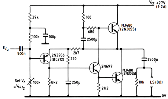
J. L. Hood Class-A Single-Ended Amplifier
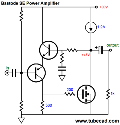
This amplifier is not a push-pull design, being more of a single-ended effort. (I think of it as being a distant relative of Nelson Pass's Zen amplifiers, as the bottom 2N3055 does allmost all the pushing and pulling, while the top 2N3055 is an active load that approximates a constant-current source.) It put out about 10W and I actually heard a working example back in the late 1970s. I found the sound extremely pleasant, but a bit too tube sounding, in the bad sense of tube sounding, a bit too rounded and too bandwidth limited. With modern, high-quality parts, however, that judgment would probably not hold true today. But were we to build it today, we could also alter the topology. For example, here is a simple single-ended, class-A (but then I repeat myself) amplifier.
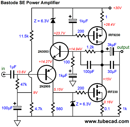
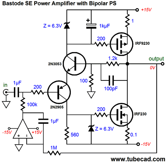
The N-channel power MOSFET works into a constant-current source (CCS) and the two transistors define the input stage. What could be simpler. Okay, other than a Nelson Pass Zen amplifier? The two transistors create a differential amplifier, which provides signal gain and allows the easy application of negative feedback. The name "Bastode" is Rene Jaeger's inspiration, the circuit being like a cascode, but not really. It could be replaced by a conventional PNP-based differential amplifier whose coupled emitters would connect to a CCS that terminated into the B+ voltage.* But the bastode is simpler and just as effective. Speaking of simple, many times I have been out having breakfast or a beer with a buddy and I draw an equally simple circuit on a paper napkin for him (of course it is a him, as so very few women would have any interest in any electronic circuit; yes, I know they exist, as I get e-mail from them, but they are as rare as unicorns ;). He loves it. He proclaims, "I want to build this; I can build this! When do we start? " I then proceed to draw the following schematic for him, which show shows the complete amplifier, sans power supply and fusing.
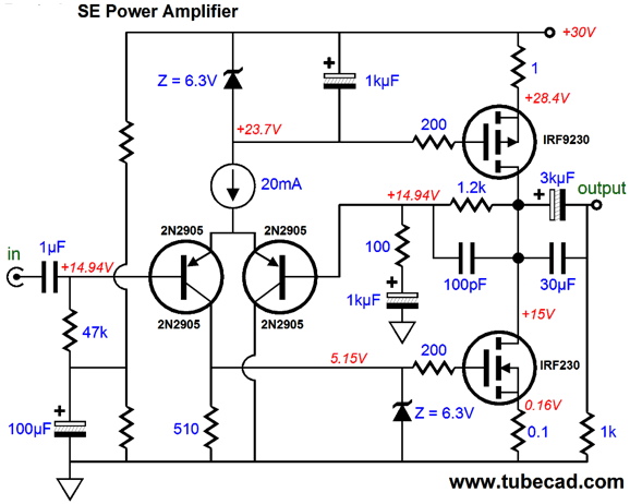
He is disheartened. "Where did the simple circuit go?" he bemoans. I tell him that it is still there, but that an actually working amplifier will require more supporting devices, such as the protecting zener for the IRF230's gate and the 100pF feedback capacitor to limit high-frequency bandwidth to below 1MHz. He doesn't like my answer and I can understand why. Perhaps, if I had only added one essential detail at a time, so at the end of three beers and ten napkins later, he could have baby-stepped himself to groking the complete, fleshed-out circuit. Perhaps not, as adding more trees just makes the forest disappear. Another group of audiophiles would have immediately sniggered, stunned by my electronic insensitivity, my bad audiophile manners. They would wonder, "What was I thinking when I added the coupling capacitor at the output? Don't I know that all capacitors degrade the audio signal?" I would then point that all power supplies must also degrade the audio signals, as they are very much in the signal path that the speakers see. For this group, I would then draw the following schematic, which would make them happy, as they cannot see the power supply capacitors, so they ignore them; entirely.
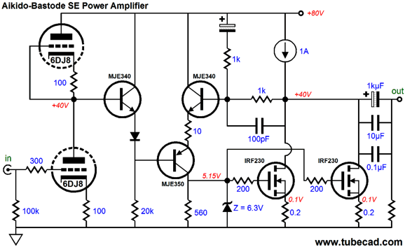
The OpAmp-based DC servo-loop takes care of the DC offset at the output, which allowed us to lose the big capacitor at the end the feedback resistor pair. In all these examples, the idle current was set to 1.6A, which should get us close to 10W into 8-ohm speakers. In spite of the low power output, this amplifier will dissipate a lot of heat, as the 1.6A is against 30V, which creates 48W of dissipation, so large heatsinks will be required. But with a 32-ohm load and a goal of 32Vpk of voltage output swing, an 80V B+ (or +/-40V) would be needed and the idle current could be set to 1A. Now, 80V is a lot of voltage. Enough, in fact, to run some tubes. The following amplifier is an Aikido design, although it may not look like it. The totem-pole configuration of the two 6DJ8 triodes delivers a gain equal to half of the mu, or roughly 16. They also define a two-resistance voltage divider, so 50% of the B+ ripple will leak out at the bottom triode's plate. A PSRR of -6dB doesn't sound that stellar; and it isn't, but the solid-state half of the circuit takes care of that.
The two 1k feedback resistors do not terminate into ground, but the B+, which give the solid-state half a gain of 2 (+6dB and thus the total gain of the amplifier equals the mu of the triodes used) and eliminates the B+ ripple from the output. See Blog Number 141 for more explication of how this miracle occurs.
But if you are willing to use a class-A, push-pull amplifier, you need only choose an existing class-AB, push-pull design and bump up its idle current to 500mA; you might need to also add, or to subtract, output devices. Designs from Erno , Bob Cordell, John Curl, Rod Elliott, Jean Hiragra, John Linsley Hood, Nelson Pass, Douglas Self, Randy Slone, and many others. (Sorry if I left you off the list; and I know that I have left many off the list, as I just thought of A. R. Bailey, James Bongiorno, Daniel Meyer, P. L. Taylor...)
Bob Cordell's book, Designing Audio Power Amplifiers, is a steal at $37.30 at Amazon. Bob covers every aspect of designing, not just building, a solid-state power amplifier. Randy Slone passed away recently, sadly. His book, High-Power Audio Amplifier Construction Manual, is also a must read and a bargain at $33.16.
Slone's perspective is different from Cordell's, being more focused on actual working power amplifiers instead of theory or design philosophy, so the the two books complement each other nicely. Of course, this is not what I would do, as I enjoy designing power amplifiers. In fact, I would probably experiment with a single-ended, class-A, solid-state power amplifier, but then the 500mA idle current would have to be bumped up to 1A. Moreover, I would be inclined to use power MOSFETs, rather than transistors in the output stage. Or, I might design a hybrid output stage, which ran both triodes and solid-state devices in parallel. Indeed, with the 32-ohm load, an all-tube OTL power amplifier would not be too difficult to design.
Quad Current-Dumping Topology
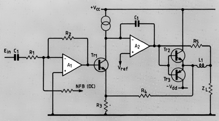
True enough, both my IMC approach and the Quad design share both a common goal, better sound on the cheap, and use similar components, a small class-A amplifier and a not class-A amplifier. But they differ in that my approach does not extend a global negative feedback loop to where the speaker attaches, which allows me to treat the small class-A amplifier and the IMC as discrete pieces of equipment that each reside in its own chassis. In contrast, the Quad current-dumping amplifier in single circuit that must be enclosed it its own chassis. Long ago, I was so taken by the Quad current-dumping concept that I translated it into a tube-based power amplifier. Unfortunately, I haven't been able to find the schematic. If I remember correctly, I had planned on using a single EL84 in a single-ended configuration along with a pair of EL34 output tubes in a lean class-AB, push-pull output stage.
A. M. Sandman's Class-S
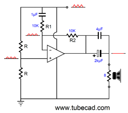
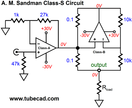
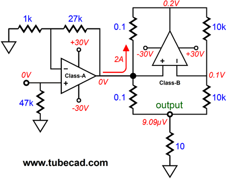
The small class-A amplifier delivers its clean output signal to the class-B amplifier. The class-B amplifier does the best job it can and the a small class-A amplifier cleans up the mess created by class-B amplifier. The speaker then sees a clean signal. I have seen his topology described as being an impedance multiplier circuit of sorts, which it is sort of, but not really. Let me explain; if both amplifiers were perfect, giving rise to zero distortion, the load that the small class-A amplifier would see would approach infinity.
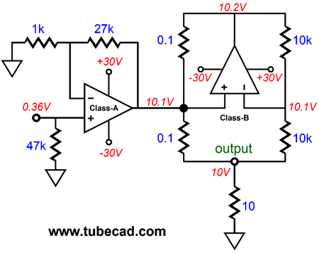
Note how the class-A amplifier delivers no current into the load. On the other hand, if the class-B amplifier put out 100% distortion, it was turned off in other words, then the small class-A amplifier would see an 8.1-ohm load, so no impedance multiplying would obtain. In other words, the amount of work the small class-A amplifier must perform depends on how dirty the class-B amplifier is, as it must deal with the delta, the departure from perfection produced by the class-B amplifier. If the class-B puts out 0.1% THD, the small class-A amplifier will have little work to do; if the class-B amplifier puts out 10% distortion, the small class-A amplifier will have 100 times more work to do.
Here is a very simple example: imagine that the class-B amplifier suffers from a 200mV DC offset, which can be viewed as a DC distortion. The class-A amplifier's negative feedback will force its output to 0V, but by doing so, it must deliver a steady 2A of current flow to counter the class-B amplifier's DC offset. Effectively, the load impedance the class-A amplifier sees is 0.1 ohms. In addition, the class-A amplifier's output impedance must be extremely low, so you can forget about using a tube-based OTL amplifier in place of the class-A amplifier. One workaround is to replace both 0.1-ohm resistors with 1-ohm resistors. But this will increase the output impedance that the speaker sees to about 1 ohm. As Robert Heinlein like to say TANSTAAFL (There ain't no such thing as a free lunch). Do Not get me wrong here: I think that Dr. Sandman's class-S approach is brilliant. Just bear in mind that the small class-A amplifier must be truly exemplary and the class-B should be as clean as possible. (In fact, I would use a class-AB amplifier, such as the LM3886, in place of a true class-B amplifier, as my goal would be the purest amplification, not the lowest dissipation.)
Next Time
* Conventional Differential Input stage
Of course, we could get more fancy and use a current mirror in stead of the lone 510-ohm collector resistor and/or add emitter resistors.
For those of you who still have old computers running Windows XP (32-bit) or any other Windows 32-bit OS, I have setup the downloadable availability of my old old standards: Tube CAD, SE Amp CAD, and Audio Gadgets. The downloads are at the GlassWare-Yahoo store and the price is only $9.95 for each program. http://glass-ware.stores.yahoo.net/adsoffromgla.html So many have asked that I had to do it. WARNING: THESE THREE PROGRAMS WILL NOT RUN UNDER VISTA 64-Bit or WINDOWS 7 & 8 or any other 64-bit OS. I do plan on remaking all of these programs into 64-bit versions, but it will be a huge ordeal, as programming requires vast chunks of noise-free time, something very rare with children running about. Ideally, I would love to come out with versions that run on iPads and Android-OS tablets.
//JRB |
I know that some readers wish to avoid Patreon, so here is a PayPal button instead. Thanks. John Broskie
Kit User Guide PDFs
E-mail from GlassWare Customers
High-quality, double-sided, extra thick, 2-oz traces, plated-through holes, dual sets of resistor pads and pads for two coupling capacitors. Stereo and mono, octal and 9-pin printed circuit boards available. Aikido PCBs for as little as $24 http://glass-ware.stores.yahoo.net/
Support the Tube CAD Journal & get an extremely powerful push-pull tube-amplifier simulator for TCJ Push-Pull Calculator
TCJ PPC Version 2 Improvements Rebuilt simulation engine *User definable
Download or CD ROM For more information, please visit our Web site : To purchase, please visit our Yahoo Store: |
|||


| www.tubecad.com Copyright © 1999-2014 GlassWare All Rights Reserved |