| John Broskie's Guide to Tube Circuit Analysis & Design |
25 July 2008
Wristwatch
Imagine what a conversation starter it would prove. Imagine how I could make a thousand times more money selling such a wrist sundial (before the China-made replicas put me out of business) than selling PCBs. By the way, before you are tempted to send me an e-mail, I do know that a few have made wristwatches that hold nixie tubes, but a wrist-sundial is much more retro and mindbending. Just imagine all the media interest and free publicity, as the idea seems so crazy—almost as crazy as using tube-based audio gear in this digital age.
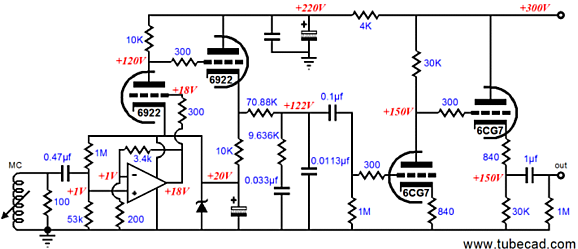
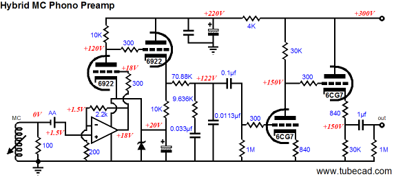
MC Pre-Preamplifiers What if we could get away without using a negative power supply rail for the super-audio OpAmp? I have presented the following capacitor-coupled hybrid MC phono preamp before. The 0.47µF coupling capacitor at the OpAmp’s input allows the 1V DC bias voltage to be developed, which allows us to get away with not using a negative power supply rail. If a negative power supply rail were added, the input coupling capacitor could be eliminated (and the 20V zener could be replaced by a few forward-biased signal diodes in series); but we then return to the problem of the negative power supply rail. If only we could find an inexpensive and readily available electric device that could pass AC signal as well a coupling capacitor and offer a fixed DC offset voltage. If only…well, what about a battery, say a AA 1.5V single cell battery? (Yes, I know that anything that cost less than $1,000 isn’t worth listening to…but maybe if some compassionate high-end-audio company could wrap the batteries in some fancy, patented, irreplaceable shrink-wrap that would up the price to a few hundred dollars…)
Note how the battery presents a +1.5Vdc bias voltage to the OpAmp; had a pure-tube circuit been used instead, as it is in the circuit below, the battery’s orientation must be reversed.
Of course, the battery can be bypassed by a small-valued high-quality capacitor. But the interesting feature of using a battery as a coupling capacitor is that the battery will last as long as its shelf life, as it sees no significant current draw, as the input resistance of both the triode and the OpAmp is supremely high.
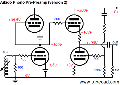
Aikido Phono Pre-Preamp
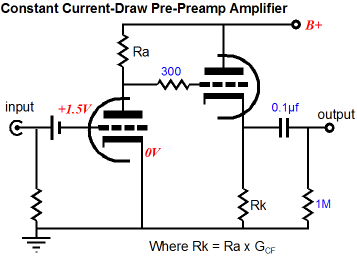
Yes, no cathode resistors are used for the input triodes; instead, the two batteries provide the required negative grid bias voltage for top and bottom triodes. Some are no doubt thinking that the two batteries could be used place of cathode resistors, which is true, as shown below. The batteries, however, are now very much in the current paths within the amplifier stage and they face a charging current, which may damage an alkaline battery, although it would charge a NiH battery.
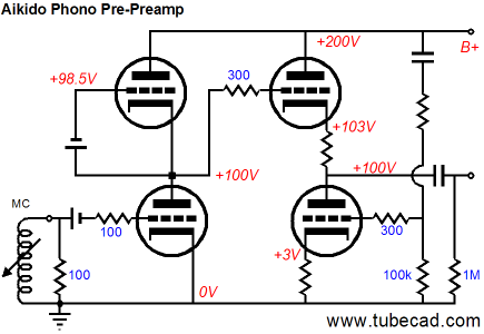
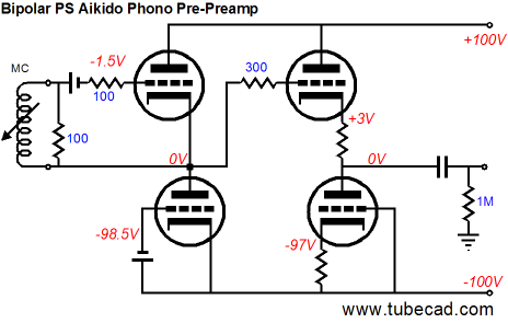
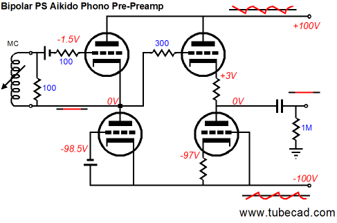
Now that we have done our mental stretching exercises, we can move on to the truly interesting Aikido phono pre-preamp. The circuit below uses a bipolar power supply and the top-leftmost triode is the input tube. The bottom-leftmost triode is but an active load for the top triode, which functions as a grounded-cathode amplifier. What? That has to be backwards, doesn’t it?
The top triode is configured in an inverted topology, wherein the input signal phase is preserved and the gain, output impedance, and distortion are identical to a conventional grounded-cathode amplifier. How can that be? Note that there are no ground connection at the amplifier’s input; instead, the cartridge’s coil spans the top triode’s cathode and grid. Remember that this coil floats relative to ground in most turntables (apparently a few British turntables ground one cartridge lead within the tone arm). Also note that the two-resistor AC voltage divider that is used in the conventional Aikido gain stage to inject power-supply noise in to the output stage's bottom triode is missing; instead, the output stage’s bottom triode has its grid attached directly to the negative power supply rail. What is going on here is that both sets of triodes in series define two equal-resistor voltage dividers, which means that as long as the positive and negative power supply rails share the same amount of ripple, differing only in phase, the midpoint for these voltage divider is at a noise null.
Ok, what about the output coupling capacitor? Why use it, when the output is already at 0 volts? If all the tube, resistors, and batteries are perfectly matched, then the output coupling capacitor could be eliminated. With real parts, however, expect a big DC voltage offset, say 5V to 10V. Ok, what happened to the usual Aikido safety resistors? They were left out in an effort to realize the least noise at the output. In a line stage amplifier, the noise contribution is swamped out by the tube noise, but in a phono preamp, we cannot accept any extra noise sources. //JRB
|
E-mail from GlassWare Customers
High-quality, double-sided, extra thick, 2-oz traces, plated-through holes, dual sets of resistor pads and pads for two coupling capacitors. Stereo and mono, octal and 9-pin printed circuit boards available.  Aikido PCBs for as little as $24 http://glass-ware.stores.yahoo.net/
Support the Tube CAD Journal & get an extremely powerful push-pull tube-amplifier simulator for TCJ Push-Pull Calculator
TCJ PPC Version 2 Improvements Rebuilt simulation engine *User definable
Download or CD ROM For more information, please visit our Web site : To purchase, please visit our Yahoo Store:
|
|||


| www.tubecad.com Copyright © 1999-2008 GlassWare All Rights Reserved |