| John Broskie's Guide to Tube Circuit Analysis & Design |
| 31 July 2014
Thanks I am sure that most land upon this site via a Google search, as many of the e-mails I get instantly reveal that the writer didn't read the blog post, but only found the schematic in an image search of tube amplifiers, then shot off an e-mail. (I wish I had $1 for every e-mail that asked if the Aikido could power two 12-inch woofers.) Aggravating this problem is my approach of providing many progressive iterations of a circuit, before arriving at the last circuit, the circuit that I would build. Image-search engines only catalog images, so when one of my tentative offerings is revealed, the eager web-surfer hasn't read the accompanying text prior to sending me an inquiry about some failing or limitation of the circuit that I had, in fact, pointed out in the blog post. Of course, most of these web-surfers do not speak English, so unless they have translated my post, my words mean nothing to them. At the other extreme, however, are those avid readers who carefully read every word that I write. Just as there are bookworms (I am one myself), there are webworms who do most of their prodigious reading online. And I am always astounded when I meet in person an intense reader of my blog. What usually happens is that I start telling a story and he finishes it for me, having already read about it here. Indeed, I have met a few readers who have told me that they do not always get my schematics, but they do get my text. Much like the old joke about a man who actually does buy Playboy magazine to read the articles, I have a few readers who visit this blog primarily to read the words. Indeed, I know that I have at least one blind reader, who—like my blind high-school friend, Dennis—builds electronic projects. Truly impressive.
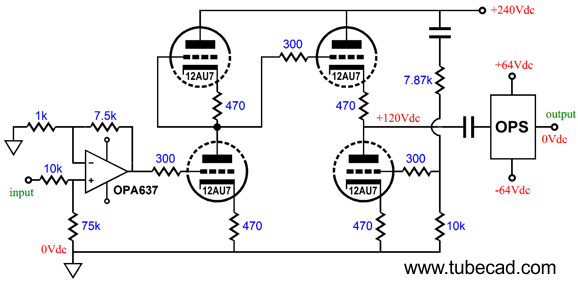
Three-Technologies Hybrid Amplifier My first thought was that, while such an arrangement had much to offer, the actual implementation would prove difficult, as DC coupling through out would prove both dangerous and difficult. Dangerous? Imagine the amplifier cold and just turned on or the tube missing from its socket. Then there was the issue of rail voltages, as most audio-grade FETs cannot tolerate too much, but tubes require lots of voltage, which the MOSFETs faling somewhere i between. My second idea was that it would probably be better to use preexisting bite-sized chunks of proven circuitry. For example, the IC OPA637 single-OpAmp holds an FET input stage and sounds quite good, almost tube like, perhaps a bit too reticent and laid back, but certainly not brittle or scratchy. The Aikido tube-based gain stage can swing big volts with little noise. And the MOSFET-based, unity-gain output stage can deliver big watts without dragging down the driver stage. Thus:
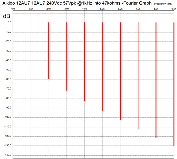
The OpAmp input stage delivers a gain of 7.5, whereas the the Aikido stage with 12AU7s delivers a gain of about 8.5, bringing the total gain up to about 63, easily enough to drive the unity-gain output stage to full power, which with ±64Vdc rail voltages would be about 200W into 8-ohm loads. Note that no coupling capacitor should be used between OpAmp and tube, as the tube's grid will end up being driven positively at full output, which would cause the coupling capacitor to become overcharged, risking blocking distortion. Speaking of full output, here is the SPICE-generated distortion graph of the Aikido stage at 57Vpk output at 1kHz.
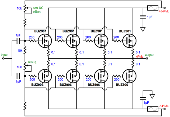
At 1Vpk out, the distortion is almost nonexistent, as would be the distortion from the OPA637. In other words, the primary source of distortion in this hybrid amplifier will come from the MOSFET-based output stage. Speaking of the output stage, not all that much is needed: a handful of resistors and two coupling capacitors and eight power MOSFETs.
Note how the top potentiometer sets the DC offset, while the bottom potentiometer sets the idle current. Also note how these two potentiometers and its resistor string fall outside the scope of the two power-supply fuses. Why? If one fuse blows, we do not want the output stage to slam into the other rail voltage; it's bad for the speakers to see a steady 64Vdc. No doubt, many are troubled by the two coupling capacitors. Do not be. The two capacitors are effectively in parallel with each other, making an effective combined capacitance of 2µF; so rather than using a single 2µF capacitor, we use two 1µF capacitors. Depending on the total resistance presented by the resistor string and potentiometers, much smaller capacitors could be used, say two 0.1µF types. How about adding a DC servo, so the DC offset is automatically taken care of? But how do you do it with two coupling capacitors? The answer is simple, use two 1M resistors rather than one to connect the servo's OpAmp's output to the capacitors. (Depending on the resistor string values, two lower-value resistors might be needed, say two 300K resistors, rather than two 1M resistors.)
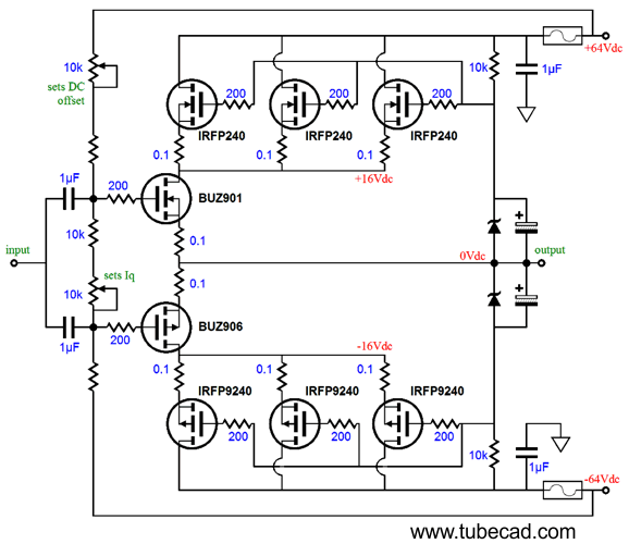
The best-sounding MOSFETs are likely to be the lateral type, which are also the most expensive. (When is it otherwise?) Last time I looked, the BUZ901 and BUZ906 MOSFETs in the TO-247 platic package were over $20 each. Of course, if you are used to buying NOS tubes, such prices are ridiculously cheap. For those who balk at spending $300 on a single tube, $160 worth of silicon per channel is insanely expensive. One workaround is to lower the power supply rails and use only one pair of lateral power MOSFETs per channel; or, use the much cheaper HEX MOSFETS, such as the IRFP240 and IRFP9240. A third possibility is to get sneaky, as here is a sneaky way to use fewer lateral MOSFETs, but still provide sweet sound and big watts:
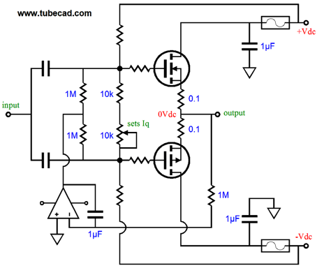
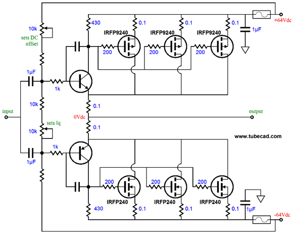
The BUZ901 and BUZ906 MOSFETs control the current conduction in this output stage, but dissipate only one fourth of the heat at idle. The IRFP240 and IRFP9240 MOSFETs create a 32Vdc (±16Vdc) voltage window, within which the lateral MOSFETs operate. As the output voltage swing ups, the HEX MOSFETs follow, maintaining the same 32Vdc voltage window for the lateral MOSFETs. Think of it as being something like a high dissipation class-G output stage. Another possibility is force greater linearity on the HEX MOSFETs. The following is a compound feedback-based output stage, which uses the NPN & PNP transistors (MJE 340 & MJE350) to control the power MOSFETs. This is a short, fast negative feedback loop that keeps the MOSFETs in line.
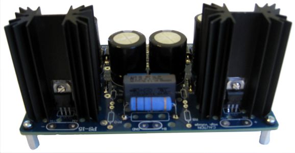
No matter which output stage is chosen, many power-supply voltages are needed, alas. The OpAmp requires between ±12Vdc to ±15Vdc; the Aikido stage, between 200Vdc to 300Vdc; and the output stage, between ±30Vdc to ±70Vdc. The new GlassWare PS-15 power supply kit would work well here, as its dual low-voltage regulated power supplies can be connected to form a regulated ±12Vdc bipolar power supply, which could power both the OPA637 Opamps and a DC servo if needed; and its high-voltage, RC filtered power supply can easily deliver the Aikido stage's B+ voltage. The 12AU7 heaters would require an H-PS-1 referenced to about 60Vdc or could be powered by a 6.3Vac or 12Vac AC winding.
A 240Vac secondary will rectify up to about 330Vdc, which the PS-15's RC filter can drop down to 240V. The 12AU7-based Aikido stage will draw about 13mA per channel, so a 6800-ohm RC resistor would do the job in a monobloc amplifier. In a stereo power amplifier (two channels within one chassis), a 3300-ohm RC resistor would be used.
Next Time
For those of you who still have old computers running Windows XP (32-bit) or any other Windows 32-bit OS, I have setup the download availability of my old old standards: Tube CAD, SE Amp CAD, and Audio Gadgets. The downloads are at the GlassWare-Yahoo store and the price is only $9.95 for each program. http://glass-ware.stores.yahoo.net/adsoffromgla.html So many have asked that I had to do it. WARNING: THESE THREE PROGRAMS WILL NOT RUN UNDER VISTA 64-Bit or WINDOWS 7 & 8 or any other 64-bit OS. I do plan on remaking all of these programs into 64-bit versions, but it will be a huge ordeal, as programming requires vast chunks of noise-free time, something very rare with children running about. Ideally, I would love to come out with versions that run on iPads and Android-OS tablets.
//JRB |
I know that some readers wish to avoid Patreon, so here is a PayPal button instead. Thanks. John Broskie
Kit User Guide PDFs
E-mail from GlassWare Customers
Aikido PCBs for as little as $24 http://glass-ware.stores.yahoo.net/
Support the Tube CAD Journal & get an extremely powerful push-pull tube-amplifier simulator for TCJ Push-Pull Calculator
TCJ PPC Version 2 Improvements Rebuilt simulation engine *User definable
Download or CD ROM For more information, please visit our Web site : To purchase, please visit our Yahoo Store: |
|||


| www.tubecad.com Copyright © 1999-2014 GlassWare All Rights Reserved |