| John Broskie's Guide to Tube Circuit Analysis & Design |
| 12 January 2013  Not done? Really? Even more Circlotron? Yes, alas. I doubt that even ten more posts on the Circlotron would satisfy the demand for more explication of this puzzling circuit. In fact, I am surprised that no www.circlotron.com web site exists. Although I could create scores of new Circlotron circuits, some all-tube, some hybrid, and some all-solid-state, what is really needed is more understanding of the Circlotron inner workings. For example, why does placing the ground connection at the middle of the load make such a big difference? If you cannot answer that question, then you have a lot more to learn about the Circlotron. But let start with with some Circlotron history.
Circlotron History
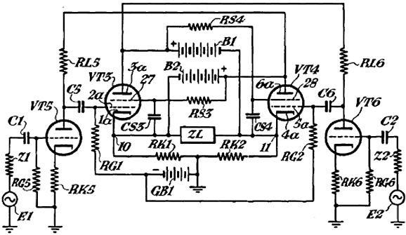
Then in 1951, Cecil T. Hall applies for a patent (US 2,705,265) for his Parallel Opposed Power Amplifier, which is a beautiful circuit that uses pentodes and no output transformer. Mr. Hall received his patent in 1955.
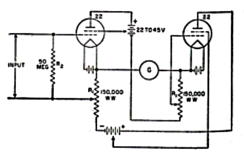
In Finland, Tapio Köykkä applies for a patent for his Push-pullforstarkare in 1952 and is awarded the patent in 1954.
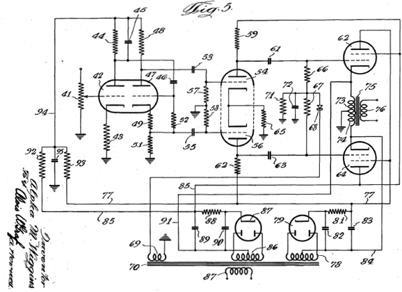
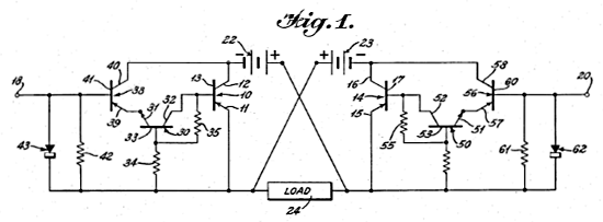
Mr. Köykkä's Circlotron is interesting. Note how he feeds the right output pentode its inverted input signal. Then in 1954, Alpha M. Wiggins submits for patent his "High Fidelity Audio Amplifier," which was granted in 1958 (US 2,828,369). ("Alpha" now there's a cool name. Was his kid brother named Beta?)
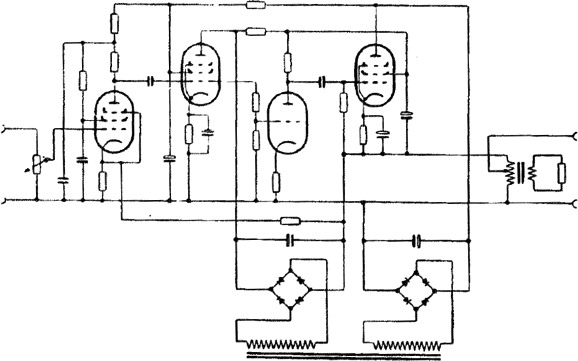
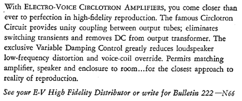
This is a fine design, suitable for framing and hanging on your wall. Then in the mid 1950s, Electro-Voice starts selling Circlotron power amplifiers based on Wiggins' design (he worked for Electro-Voice). Here is an excerpt from an Electro-Voice ad:
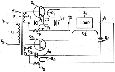
The solid-state Circlotron was patented in 1959 by A. W. Donald III.
In 1964, A. S. Goldsmith patented a simple diode-biasing method for a transistor-based Circlotron.
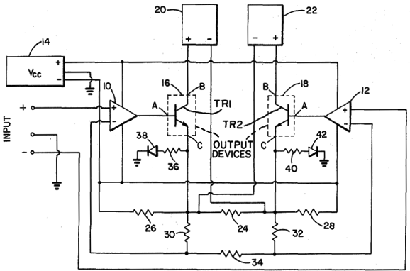
More recently, in 1980, the great James W. Bongiorno patented the basis of his clever Sumo Nine power amplifier.
Split-Load Phase Splitter and the Circlotron
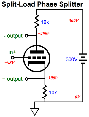
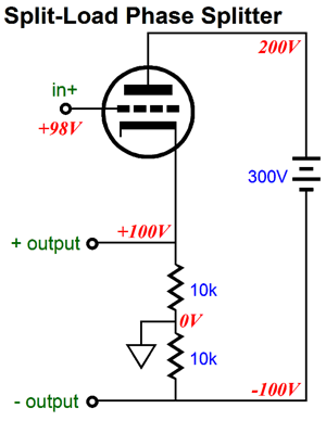
Like the Circlotron, this circuit creates controversy. Some hate it, some love it. Many argue over what its output impedance is. Is it high? Is it low? Are the two outputs dissimilar in output impedance? The answer(s) depend on where ground is located and how the load(s) attach*. In the above schematic, ground is located at the bottom of the cathode resistor. Thus, the non-inverting output presents an output impedance (relative to ground) that is equal (Ra + rp) / mu || Rk, which is fairly low. The inverting output presents an output impedance (relative to ground) that is equal Ra || rp + (mu +1)Rk, which is very high. Great, but we already knew that. Wonderful, but did you know what the output impedance is from one output to the other with a single load in between? The answer is 2rp/(mu + 2) in parallel with the plate and cathode resistors, which is fairly low. Now, let's take the four essential devices, the two resistors, one triode, and one 300V battery and rearrange them. We slide the plate resistor over and under the floating power supply, so it ends up below the cathode resistor.
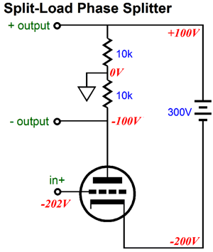
It may look radically different, but it is still a split-load phase splitter, with the same output impedances and voltage gain. Voltage Gain, what voltage gain? The split-load phase splitter offers a voltage gain of almost 2, from output to output. On the other hand, we can place the all resistors at the top of the triode instead.
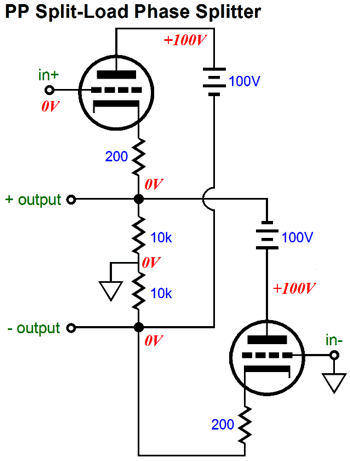
Once again, although it may look radically different, this version is still a split-load phase splitter, with the same output impedances and voltage gain. The only real difference is that inverting and non-inverting outputs have swapped position, but not attributes. (The workaround is simple, feed the triode an inverted input signal.) Now, what would happen if two of these two split-load-phase-splitter circuits were combined, so as to create a two-triode split-load phase splitter, a push-pull split-load phase splitter? Interesting question, no? The answer is the following circuit.
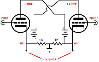
This is a push-pull split-load phase splitter, as the two triodes work in current anti-phase, so they must be driven by a balanced input signal. Wait a minute, what's the point of having a phase splitter that requires a balanced input signal? There are several answers to this question. Note the 100V, not 300V, batteries (floating power supplies). Note the OVdc outputs, which means that no current flows through the two 10k resistors at idle. And note that although not readily obvious to most, unlike the plain-Jane split-load phase splitter that uses one triode, the two output now present the same output impedance relative to ground. Since the single-triode version offered an output impedance of 2rp/(mu + 2) from output to output, this two-tube version presents half as much output impedance, or rp/(mu + 2) in parallel with R/2, where R is either the plate or cathode resistor value. And strictly speaking, this push-pull split-load phase splitter does not require a balanced input signal, as the right triode can have its grid connect to ground, not a balanced input signal.
This phase splitter will split the phase of its unbalanced input signal, but it will deliver only half the gain that a balanced input signal would yield. (I added the cathode resistors to make biasing easier.) In effect, the right triode IS SEEING an input signal, as its grid connects to the middle of the load. We cannot see the signal, because we have designated this mid-point as ground, so we place our black voltage probe there. If we designate the inverting output as ground and if we place our black voltage probe there and reference the input signal there, we will see that the right triode's grid sees 50% of the signal developed across the two outputs. Hot dang, somebody should rush to the patent office and patent this circuit quick. Well, not that I doubt the US Patent Office would issue you a patent, but you should pause to realize that this is an old, familiar circuit that you have seen thousands of times before; it's just drawn differently. Here is what it usually looks like.
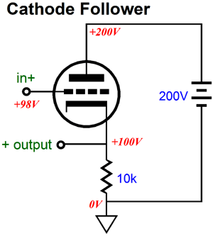
Amazing, no? Not really. What is truly amazing is how few understand the importance of where ground falls within a circuit. The example I love to give is of the man who returns a 9V battery he has just purchased, claiming that it is defective. He tells the store owner that he needs a -9V battery, not +9V battery, as the circuit he is trying to build only holds a negative power-supply rail, not a B+. The store owner then takes the 9V battery into the backroom and draws with a marker a minus sign in front of the "9" and returns the battery to the customer, who is pleased and leaves. Well, was the battery a +9V or -9V battery? It all depends on where we place the ground. In our tube audio circuits, where we place the ground not only alters our DC voltage measurements, it alters where the input signal finds its voltage reference within the circuit. This second aspect, unlike the first one, is huge. A cathode follower offers a low output impedance and near unity gain, because the ground falls at the bottom of the cathode resistor.
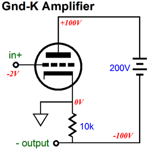
Had ground been located at the top of this resistor, this circuit would no longer be a cathode follower, as it have transformed into a grounded-cathode amplifier, with its concomitant voltage gain, phase inversion, and much higher output impedance.
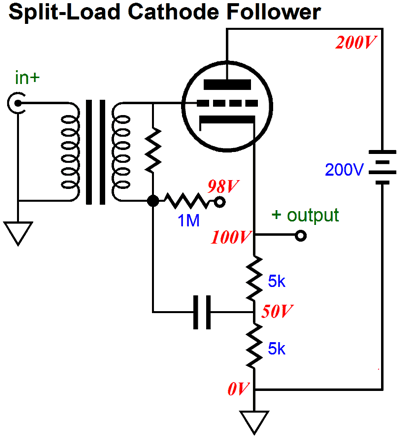
Why the huge difference due to moving the ground? In the grounded-cathode amplifier, the ground is located at the cathode, so the input signal only spans from cathode to grid. Thus, the input signal is given at full strength; but in the cathode follower, the input signal must span from the grid to the bottom of the cathode resistor, so any voltages across the cathode resistor will subtract from the signal delivered to the grid, which is why the cathode follower does not deliver gain. If place the cathode follower's signal ground at mid-point on the load, we do get a higher output impedance and some gain, almost 2.
The 1:1 isolation transformer allows us to feed the cathode follower an input signal that is split-load referenced, so unlike a cathode follower, only 50% of the signal that appears across the two cathode resistors is subtracted from the input signal at the grid. The result is voltage gain, about 1.85 with a 6DJ8 in the above circuit and an output impedance that equals 2rp/(mu + 2), or about 175 with a 6DJ8 in the above circuit. Place two of these in horizontal parallel and you have a Circlotron (or a "Parallel Opposed Power Amplifier" or a "Push-pullforstarkare").
Push-Pull Cathode Followers
The split-load phase splitter effectively terminates into the output. Thus, it will deliver the required asymmetric signals required to drive both output tubes as cathode followers. This amplifier could be configured more like the classic Futterman OTL circuit, but then it would require a large coupling capacitor or high-voltage negative power-supply rail. The floating 100V power supply allows us to avoid the DC offset. Well, at least it does once the amplifier is warm and running; but at start up, when the tubes are still cold and the rail voltage are already established, the output will sit at -30Vdc. In other words, either a coupling capacitor, albeit a lower voltage capacitor than the Futterman would require, or a relay and safety circuit would be needed. The real advantage this amplifier offers over the Circlotron is that it accepts an unbalanced input signal and offers a lower output impedance.
Next Time
* Balanced Zo Split-Load Phase Splitter When the following result obtains, the balanced output impedance will obtain. [(Ra + rp) / (mu + 1)] || Rk = Ra || [rp + (mu + 1)Rk] After many steps, we arrive at this formula: Ra = rp•Rk / (rp + mu•Rk) So, we first specify a cathode resistor (Rk) value, then we do the math to find the required (smaller) plate resistor (Ra) value. //JRB |
I know that some readers wish to avoid Patreon, so here is a PayPal button instead. Thanks.
John Broskie
Kit User Guide PDFs
E-mail from GlassWare Customers
High-quality, double-sided, extra thick, 2-oz traces, plated-through holes, dual sets of resistor pads and pads for two coupling capacitors. Stereo and mono, octal and 9-pin printed circuit boards available.  Aikido PCBs for as little as $24 http://glass-ware.stores.yahoo.net/
Support the Tube CAD Journal & get an extremely powerful push-pull tube-amplifier simulator for TCJ Push-Pull Calculator
TCJ PPC Version 2 Improvements Rebuilt simulation engine *User definable
Download or CD ROM For more information, please visit our Web site : To purchase, please visit our Yahoo Store: |
|||


| www.tubecad.com Copyright © 1999-2013 GlassWare All Rights Reserved |