| John Broskie's Guide to Tube Circuit Analysis & Design |
Low Dissipation SE Class-A? |
||||
28 January 2005
Taylor source follower on steroids First of all, I am a little fearful to describe any circuit that can be exploited by a marketing department. Hype sells and today’s hot audio-gear adjectives include “single ended” and “class-A.” Unfortunately (at least for marketing and finance departments), these adjectives unavoidably necessitate low efficiency and high heat dissipation. The only problem with big, heavy, inefficient, and expensive is that is big, heavy, inefficient, and expensive. What if it were otherwise? What if a small, light, efficient, and cheap class-A, single-ended, amplifier could be made? Well, until the laws of physics get amended or revoked, the engineering department will have its hands tied; on the other hand, the marketing department is not so constrained, as long as the circuit is odd or complex enough to confuse most audiophiles, then generous loopholes are waiting to be exploited. A quick aside While on the topic of foolish audio sales people, I was surprised by the number of clowns running demonstrations of disgustingly expensive audio equipment at the CES show I attended recently. Back in the old days, when stereo sales were soaring, say 1979, it was common to walk into a stereo store that placed all the electronics on the back wall and all the speakers against the front wall. You would sit and listen away as the salesman would control which amplifier and loudspeakers you heard. Regrettably, a few salesmen were content to leave at that; instead, they would ride the volume control as you listened. The result was SpecTacUlaR, as the bass rumbled just to the point of breakup on the first notes of Richard Strauss’s Also Sprach Zarathustra and then the volume would relapse into sane levels as the trumpets began to sound (when the 50% distortion would be more noticeable). The first time I discovered that this was happening, I turned around and asked what the salesman was doing. He looked at me in a puzzled way and said that he was just demonstrating the loudspeakers. "Great," I asked, "does this mean if I buy them, you’ll come home with me and constantly adjust the volume control whenever I play the stereo? He could not understand what I was getting at. Well, with the advent of remote controlled volume, he would find lots of work at the CES, where many salespeople discreetly adjusted the volume from afar and the result was sPecTAcuLaR. Now, do not get the wrong implication here: I am not anti-audio salespeople (or anti-audio salons). In fact, I believe if you find a good one, he will be the best friend your sound system ever had. And I have known as many good audio salesmen as bad. Furthermore, if you go to an audio store and spend an hour of their time listening, only to buy the same equipment over the net, then you have stolen from the that store, just as much as a shoplifter would have, as time is money and you have stolen their time. This doesn't mean that every time you listen, you must buy; it means that every time you listen, you might buy.
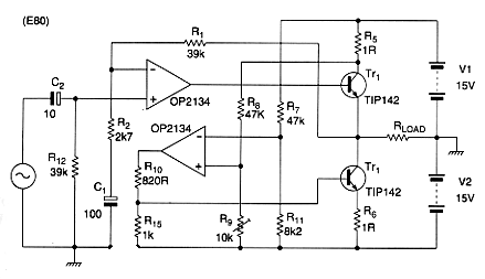
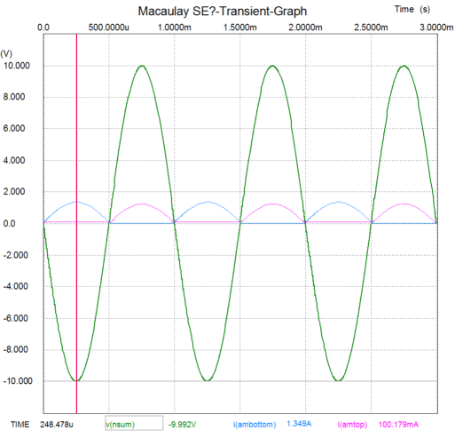
For example, if the input signal swings negative, the voltage drop across the top 1-ohm resistor decreases, which is relayed as a positive pulse to the OpAmp’s non-inverting input, which in turn triggers a positive swing of its output, which furthers the bottom output device’s conduction, which allows it to cope with the bottom half of the waveform. But the top output device can never conduct less than 100mA, as the OpAmp will always counter any dip below 100mA with an increase in conduction of the bottom tot device to force the top device to conduct at least 100mA. What purpose is served by the other set of resistors that bridge the positive and negative power supply rails, whose nexus connects to OpAmp's negative input? They serve two purposes: they sidestep the power supply noise and the rails' collapsing voltage under heavy use (in a real class-A amplifier, heavy use does not collapse the rail voltages; just as for a Marine, war does not over tax him, as he was already over taxed). Clever, no? Yes, indeed and Mr. Macaulay well earned his prize, but is it really class-A? Is it really single ended?
If a thousand EE professors were shown the graph above, How many would immediately think: single-ended class-A? “But as least one output device always conducts—see how the red line never touches the zero line—so we can advertise it as a single ended class-A amplifier,” the adman thinks. Let’s downshift a bit and think about this. The only reason we care about any of the amplifier classes of operation is because they impart some useful information. We know that class-B amplifiers run cool and dirty and that class-A amplifiers run hot and clean; much as we know that a Welch corgi is short and a Russian wolf hound is tall. But what if some malicious breeders create towering corgis and stumpy wolf hounds? The dogs might make great pets, but the labels, “corgi” and “wolf hound,” would lose informational content. I believe that this topology, like several others, does not really fall within the strict classes of operation taxonomy, as it is fundamentally asymmetrical in its operation. In a symmetrical class-A push pull amplifier, the two output devices completely overlap each other, so that the distortion is low (no crossover distortion, as neither device ever ceases to draw current) and the output impedance is half of what one device alone could produce. But in the asymmetrical amplifier, the same class-AB problems of gm doubling, crossover distortion, and higher output impedance remain present. At last; tubes!
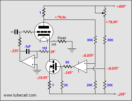
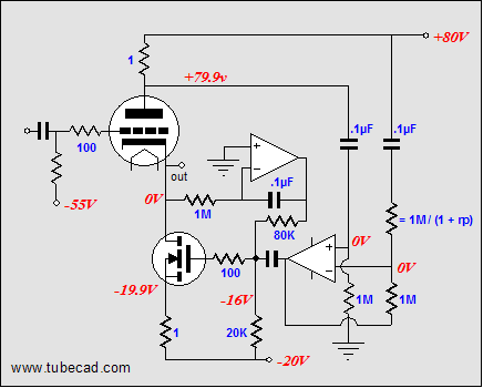
This new hybrid amplifier works in the same way as the all-solid-state amplifiers did. The left OpAmp works in a DC servo loop, which keeps the output centered to 0 volts. The right OpAmp controls the current flowing through the bottom MOSFET, which in turn controls the current through the top triode. Now, we have an interesting hybrid amplifier. Where six 6AS7s (12 triodes with plus and minus 80-volt rails in a totem pole output stage) could put out 11 watts into an 8-ohm load, only three 6AS7s would be needed to produce the same 11 watts in this topology (of course, half of the watts come from the not-so-inactive MOSFET). Not a bad circuit…except for one big problem. It is not safe. At startup, when the output tube(s) are cold and not conducting, the OpAmp will force the MOSFET to conduct wildly as it tries to force the cold tubes to conduct the require idle current. This means that the amplifier’s output will slam into the negative power supply rail, until the tubes heat up. The worst-case scenario is a certain worst case scenario, which is just what we have here. What can be done to make this amplifier safe?
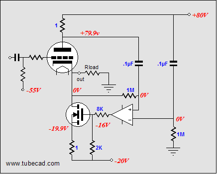
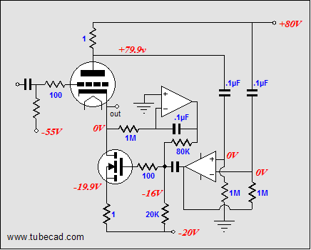
The OpAmp has been now reconfigured to work also as a DC servo loop that keeps the DC offset in line, but no longer sets the idle current. Perfection at last? No, although the idle current is not being set by the OpAmp, the OpAmp will possibly throw off the idle current setting after a prolonged burst of music, as the top 1-ohm resistor will only pulse downward, which will eventually charge the capacitor that connects to it, which will force the DC offset off zero volts. The answer? If we divide the tasks up between two OpAmps, then we have a much better chance of keeping everything inline.
I am not altogether sure there is a major conclusion here other than there many paths to driving speakers, but not many shortcuts that bypass big, heavy, inefficient, and expensive. //JRB |
Support the Tube CAD Journal TCJ Push-Pull Calculator

TCJ PPC Version 2 Improvements Rebuilt simulation engine *User definable
Download or CD ROM For more information, please
visit our Web site : | |||


| www.tubecad.com Copyright © 1999-2005 GlassWare All Rights Reserved |