| John Broskie's Guide to Tube Circuit Analysis & Design |
|
28 April 2007 High Octal
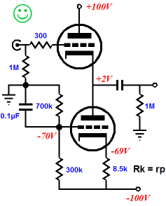
More cathode follower stuff (I have never met him [or even emailed with him], but I used to see him, a decade ago, hunting for parts at the Ham-Fest electronic flea market at Foothill College; although most of my friends will find this hard to believe, I was too shy to accost him, as he seemed deeply earnest in his quest. I get a lot of compliments, such as that I am "the new Norman Crowhurst" or "the Richard Feynman of tubes," but the complement I actually want to hear is that I am "the Bob Pease of tube circuits.") Back to tubes, in the last blog we took a large back step, reviewing cathode follower topologies, in preparation for moving forward to hybrid, DC-coupled throughout, tube-based, unity-gain buffers—which is much harder to say quickly than “No-Gain—No-Pain” line-stage. We last left off exploring cathode follower circuits with bipolar power supplies. The major advantage these topologies enjoy is the DC coupling of the input at grounded potential, eliminating the need for an input coupling capacitor. The major disadvantage these topologies present is the need for a negative power supply.
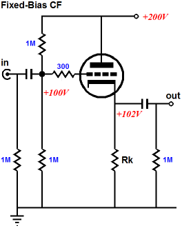
Now, let’s look at some cathode follower circuits that use only a single bipolar power supply. In the schematic below, we see a simple fixed-bias cathode follower that relies on a two-resistor voltage divider to establish the DC bias voltage for the cathode follower’s grid. The input impedance of this follower is equal to the three 1M input resistors in parallel, i.e. 333k.
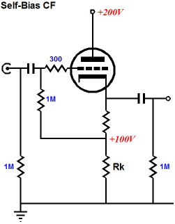
The self-biased cathode follower, shown below, uses the voltage drop across the first cathode resistor to set the negative grid voltage (negative relative to the cathode). Note that the same number of resistors is used in both circuits. So which is better? This question is more interesting than good, as “better” is not necessarily a shortened version of “better sounding,” as they both sound the same (actually, at startup, the fixed-bias will stabilize more quickly, and as a result, yield the same low distortion bit sooner). The self-bias cathode follower circuit profits from a lower impedance and less chance of cathode stripping. Lower impedance? I know that your eye sees two 1M resistor in parallel, but because of the in-phase, unity-gain output, the second 1M resistor is effectively closer to being a 20M resistance.
Regarding tube safety, the self-bias cathode follower slowly establishes its working voltages, as the triode must first conduct before the high-voltage bias voltage can be established; whereas the fixed-bias quickly develops the high-voltage bias voltage at the grid, but cathode voltage takes much longer to catch up. The last thing that the cathode wants to see when it is cold and naked (without its protective electron cloud) is a huge positive-grid voltage, as pieces of the cathode can be ripped away, pulled by the plate's strong electrostatic attraction. We should not be too alarmist here, however, as the large valued cathode resistor helps to protect the cathode to a large extent.
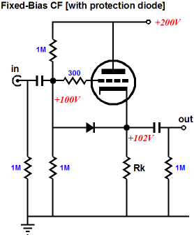
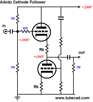
The easy workaround is to place a reversed-biased silicon diode across the voltage divider’s nexus and the cathode. Thus the diode conducts briefly at startup, then falls out of the circuit once the cathode is hot and conducting, and the cathode becomes more positive than the grid. An additional issue that is seldom mentioned is that the bipolar power supply might be cheaper to implement, as two 100µF/200V capacitors might be cheaper than one 50µF/400V capacitor (two 100µF capacitors in series hold the same amount of joules as one 50µF capacitor), as high-voltage parts often incur a hefty price penalty. Moreover, the shock danger is four times worse with a 200V B+ than with a 100V B+, so unless you touch both positive and negative power supply rails at the same time, you will be much safer working on the bipolar version. Much more damning, at least for me, is the impossibility of applying any Aikido noise-reduction trick on these two cathode follower circuits; no countervailing noise source is available. But if we are willing to add a second triode, then we can use the Aikido cathode follower topology, as shown below.
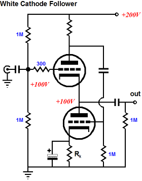
As this circuit has been covered here before, let’s move on to using a solitary White cathode follower with a mono-polar power supply.
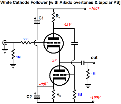
The White cathode follower is a push-pull buffer that can symmetrically swing output current in excess of the idle current, something no simple cathode follower can do. Applying an Aikido PSRR-enhancement is just one extra bypass capacitor away.
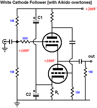
In the above schematic, we see two capacitors (C1 and C2) defining an AC voltage divider, which injects a portion of the B+ noise into the bottom triode’s cathode, which serves to offset the B+ noise presented at its grid. Some tweaking of the capacitor values will be needed. If the residual power-supply noise appearing at the output is in phase with the B+ noise, then the top capacitor is too large in value. Conversely, if the noise appearing is in anti-phase with the B+ noise, then the top capacitor is too small in value.
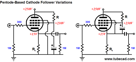
Pentode-based followers
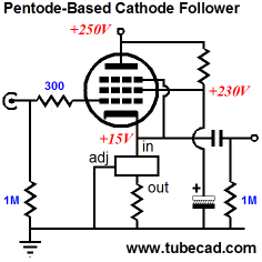
One great advantage that a pentode-based cathode follower holds over the triode-based version is that feeding the screen a clean DC voltage greatly reduces the noise through the pentode. And since the screen draws much less current than the plate, we can leverage this discrepancy to our advantage by using a large valued screen bypass capacitor. Some will cry foul, as they see the above circuit not using a pentode in the strictest sense, as the cathode and screen see two different signals, making the circuit function as a variation on the ultra-linear topology. Maybe. Still, I would want to try the above circuit and the two following circuits as well.
The last circuit makes good use of all those pentode/triode tubes out there, such as the 6AN8, 6AU8, 6AW8, 6BM8, 6BR8, 6CS8... (Did you note the pattern: all these tubes in in "8.") When searching for a suitable pentode, make sure that it is of the sharp-cutoff variety. When searching for a pentode-triode pair in one envelope, make sure that they do not share the same cathode.
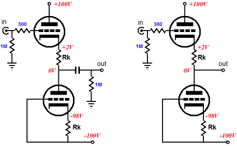
Back to bipolar power supplies
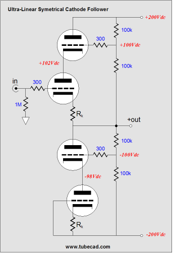
In the above circuit, the noise reduction is rather forced on an intrinsically asymmetrical topology; whereas with the symmetrically loaded cathode followers and a bipolar power supply, as shown below, the null in power supply noise occurs naturally.
Noise, noise, noise, noise… Is all you ever think about NOISE? What about slam, fluidity, and drive? Well, since you asked, slam is easy to get: never use a plate resistor with even ohmages; for example 40k totally lacks the slam of 39k and 41k. Now, some have argued that the values should also be prime, such as 37k and 41k, but it does not take advanced degrees in math to point out that 37,000 and 41,000 are not prime. (I suppose some of you really observant types are noting that if nothing else, 37,000 and 41,000 are even numbers…) Fluidity, on the other hand, is much harder to achieve, as it requires a well-lubed electron path, which explains why oil and wet-slug tantalum coupling capacitors sound so much more fluid. Drive can be the easiest and the hardest elusive sonic quality to summon from mere electronic parts. Usually, only one six-pack per listener per hour of serious listening is required (remember, if you drink, let your stereo drive instead). If, however, your religious beliefs—or doctor—prohibit such acoustically-satisfying consumption, then the only recourse is to buy the most expensive audio accessories that you can afford. Returning back to the planet Earth, the bipolar-power-supply-fed, symmetrically-loaded cathode follower can be readily hotrodded to a higher level of performance, i.e. much lower distortion. Distortion, distortion, distortion… Is all you ever think about DISTORTION? What about attack, blacker backgrounds, caramelized midrange, frosty highs, pace, presence, punch, ripe midbass, spongy bass, and swagger? (Sorry, I couldn’t help myself.)
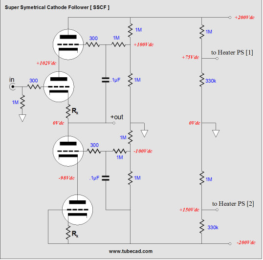
Super Symmetrical Cathode Follower
This modified cathode follower both rejects power supply noise and produces less distortion. The guiding principle behind the circuit is that a simple cathode follower is incased in a complex circuit, with the topmost triode working to provide a constant cathode-to-plate voltage across the simple cathode follower’s triode, while the two bottommost triodes work to define a constant-current source in place of a cathode resistor. So, how well does this work? If I remember correctly, about a -20dB reduction of second and third harmonic distortion. Moreover, this circuit does a superb job of rejecting power supply noise. I have seen variations on this topology that look similar, but do not perform as well, for example, the following circuit:
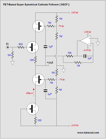
The above circuit can be seen as an attempt to achieve the same performance at a discount (no expensive coupling capacitors). How well does it work? To be honest, it’s been a long time since I played with this cheaper variation, but I do remember being disappointed by its performance. But please do some experimentation on your own and let us know what you find. Understand that with either of the last two circuits, heater-to-cathode voltage limitations are a big problem, mandating that at least two separate heater power supply be used. In these examples, one power supply should be DC referenced to -150V, while the other, +50V. By the way, the SSCF topology is not limited to tubes, as FETs or MOSFETs could be used instead.
Now, this may seem too much like gratuitous solid-state technology for many readers, but the following topology makes me profoundly jealous; I wish we had a P-version of the triode.
I guess its time to show some repentance and contrition, so here is a low-voltage version of the SSCF circuit. The 6GM8/6N27P/ECC86 is an interesting triode that looks like a 6DJ8, but works with ridiculously-low plate voltages. 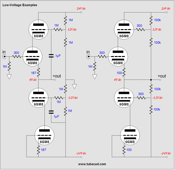
Well, I still have about twice as much to cover before moving on, but not the time required. Be sure to take advantage of the sale on octal PCBs, as there's nothing like high-octal sound. //JRB |
Support the Tube CAD Journal & get an extremely powerful push-pull tube-amplifier simulator for TCJ Push-Pull Calculator
TCJ PPC Version 2 Improvements Rebuilt simulation engine *User definable
Download or CD ROM For more information, please visit our Web site : To purchase, please visit our Yahoo Store:
The Tube CAD Journal's first companion program, TCJ Filter Design lets you design a filter or crossover (passive, solid-state or tube) without having to check out thick textbooks from the library and without having to breakout the scientific calculator. This program's goal is to provide a quick and easy display not only of the frequency response, but also of the resistor and capacitor values for a passive and active filters and crossovers. TCJ Filter Design is easy to use, but not lightweight, holding over 60 different filter topologies and up to four filter alignments: While the program’s main concern is active filters, solid-state and tube, it also does passive filters. In fact, it can be used to calculate passive crossovers for use with speakers by entering 8 ohms as the terminating resistance. Click on the image below to see the full screen capture.
Tube crossovers are a major part of this program; both buffered and un-buffered tube based filters along with mono-polar and bipolar power supply topologies are covered. Available on a CD-ROM and a downloadable version (4 Megabytes). Download or CD ROM
|
|||


| www.tubecad.com Copyright © 1999-2007 GlassWare All Rights Reserved |