| John Broskie's Guide to Tube Circuit Analysis & Design |
Post 200 28 February 2011
Blog number 200 Now, 200 blog entries, many of which could have—indeed, should have—been broken up into several separate blog postings, equals a lot of words, schematics, and graphs. Yet, I absolutely know that I could have posted twice, three times, four times more...if life had proved more compliant, less rigid. Posting isn't easy. Many readers have told me that they know how much work is required to create these posts, as they have had to produce similar presentations. white papers, and webpages for their employers. Just drawing schematics is amazingly time devouring and many would prefer to get a speeding ticket to having to write a paragraph. On the Other hand, I enjoy both these tasks, but stealing the time required is difficult. One of my favorite fantasy is where a billionaire, like Paul Allen for example, finds that he enjoys reading the Tube CAD Journal so much and believes it is important enough that he contributes sufficient funds to allow me to post freely, unconstrained by limited time and life's pressures. You see, it's not just the money that would help, rather it's the upgrade in status that such an underwriting would bestow upon this enterprise, making this blog not just a vanity-press-like dalliance, but a real job. And we all know that real jobs are powerful—powerful enough to compel respect and accommodations not only from oneself, family, friends, but the rest of the world. Until such a fantasy comes true, I will have to make do with my newly truncated work schedule (my kids require more of my time and I happily give it). I believe, however, that I might have a few solutions to at some of my difficulties in running my GlassWare business. For example, I need to post kit construction web pages for each of my circuit boards, so that a customer can see the steps required to assemble a line stage, phono stage, or power supply. Pixels are free, or almost free, so only a fool would be niggardly with them. In other words, unlike printed matter, it is super easy and cheap to take color photos and post them on the web. And while contemplating how American gun makers define their product creation schedules, I might have gleaned the right way proceed with the Aikido kits. Somehow, I have to find a way to cut down on e-mail. This website got 422,000 hits last week (there were more hits in previous weeks). There are porn sites that would welcome such a big number. One day I fully expect to break a million a week. The problem with such success is that it garners a lot of e-mail. For example, in spite of three layers of spam filtering, I spend an easy hour a day just deleting spam e-mail; and I could easily, easily spend eight hours a day answering e-mail.
Tetra Phono Stage Update Many LPs exhibited a live quality that is altogether missing from the equivalent CD version. In fact, I couldn't ignore the startlingly live sound resurrected from these old LPs—even when I wanted to do so. Background music became foreground music. Often, I had to get up and walk into the loudspeaker's sweet spot, because the music beckoned my unalloyed attention. I just wish that I didn't hate having to flip LPs every 20 minutes. Surely, these small improvements to the PCB could not so greatly increase the sound quality over the original Tetra PCB. No, they couldn't, although we should never discount how small, marginal, almost insignificant improvements in sound quality can produce huge increases in our perception. How so? Semantic content. Music is more than just sound, vibrations transmitted through an elastic substance, such as air; it is a medium for meaning. Lyrics can tell a story or at least convey a mood or emotion. So, too, even purely instrumental music can paint a continuous, unified, and evocative composition. Music is chockfull with meaning. And the difference between not getting it and getting it is infinity.
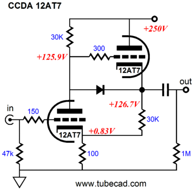
Tetra & Positive Feedback The following circuit shows how a small amount of positive feedback can be introduced.
The input tube's cathode sees varying voltage developed by the varying current flowing through the cathode follower second stage and the shared 100-ohm cathode resistor. In this example, since both triodes should see close to the same current variations, albeit in anti-phase, the 100-ohm resistor should develop a fixed voltage. Because the cathode follower does not yield perfect unity gain, the resistor will see a small degenerative signal. In others words, hardly any positive feedback, if any at all. But if we use different triodes and differing idle currents, we can harness much more positive feedback.
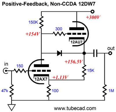
Sadly, the 12DW7 cannot be used on the Tetra phono PCB, but it would make an interesting gain stage in a hardwired phono preamp. This configuration results in +40dB (100x) of gain and offers very low distortion and and an output impedance of about 500 ohms. I know many readers are doing some quick math along these lines: +40dB of gain -20dB of insertion loss from a passive RIAA EQ network plus +40dB of gain from a second gain stage yields +60dB of gain, with no step-up transformer. The only real problem is that the 12AX7 is quite noisy compared to other higher-transconductance tubes, such as the 6N1P.
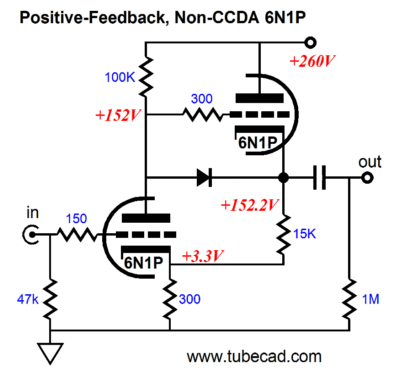
The above circuit delivers a gain of +35dB. So, as you can readily see, even in this circuit, with its 10-to-1 current ratios, not a lot of positive feedback is being employed. Is it worth the effort? Absolutely; in fact, it requires less effort and expense than having to find and buy a suitable cathode resistor bypass capacitor. What I think is going on is that the positive feedback is causing a slight expansion on the sound, not a lot, just enough to trick the ear. Here's a somewhat sexist analogy (apologies to my ten female readers): you look out your dirty kitchen window, grit-covered and dusty, and you see your beautiful next-door neighbor practicing yoga in her backyard, wearing a snug spandex body suit. You aren't surprised, as she is a world-famous yoga instructress and she recently has given you a copy of the DVD that she sells, wherein she displays her fine form and her taut features in HD BluRay 1080 LPI. In fact, you had just been watching the DVD on your 60-inch plasma TV. The TV screen certainly presents a cleaner view, but you find the live presentation much more compelling. Well, it's sort of like that with this phono stage. Sure LPs suck, warped and noise-filled as they are; and I don't plan on giving up on the ease of a computer-based server system... Still, the liveliness, the sprightliness is altogether compelling. (Now, I have to assemble an positive-feedback-based CCDA line stage.)
More Super Triode Circuits
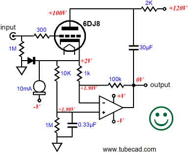
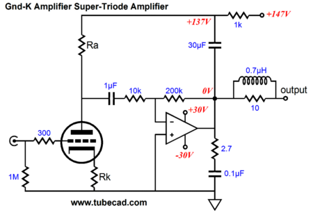
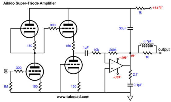
The triode's cathode delivers the input signal to the solid-state power amplifier and the triode's plate attaches to the power amplifier's output via the 30µF capacitor, controlling the solid-state power amplifier's output as a result. A GainClone chip amplifier, such as the LM1875 or LM3886 is what I had in mind, but a solid-state power amplifier based on discrete components would work just as well. The output signal is inverted by the power amplifier. This brings up an interesting question: Can we build a Super-Triode circuit that does not invert the phase at its output? Yes, we can. The following amplifier is amazingly simple and does not invert the input signal's polarity at its output.
The tube-based input stage will invert its input signal at its plate, but the solid-state power amplifier is configured in the inverting mode, so the two inversions cancel, just as two negative number multiplied against each other result in a positive number. Our first impression is that this hybrid power amplifier must develop a huge voltage gain, as the triode's gain looks as if it will be multiplied by the solid-state amplifier's gain of 20. In fact, the 30µF capacitor that spans from the power amplifier's output to the top of the triode's plate resistor limits the effective gain to something less than the triode's mu. Remember, as the plate swings negatively, the solid-state amplifier's output swings positively, thereby reducing the triode's voltage gain. Before moving on to the following variations, make sure you understand how this very simple circuit works, how the phase is preserved, how the output impedance is kept low, how the tube controls the solid-state power amplifier. No doubt, the following SRPP-based Super Triode amplifier will please the SRPP fans.
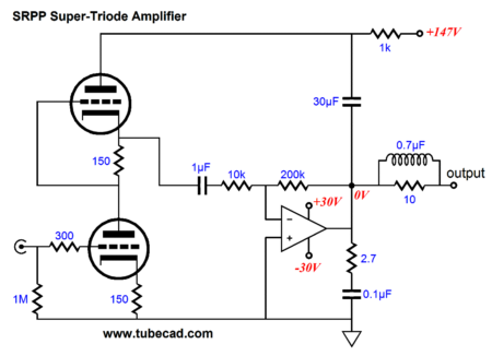
The bottom triode's plate resistor has been replaced by an active load, made up from an additional triode. This SRPP variation will provide about the same performance as the grounded-cathode amplifier variation we started with, but it does solve the problem of what to do with the second triode found in many tube envelopes, such as the 6DJ8, 6SN7, 12AU7 I, however, would use the second triode in a different topology, the CCDA.
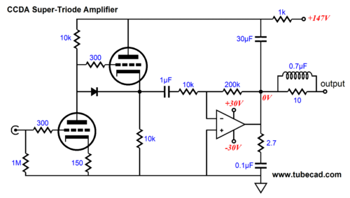
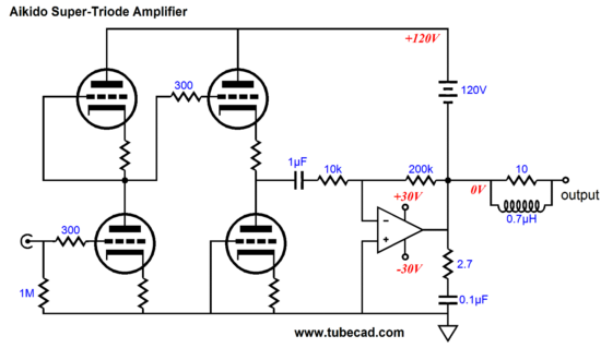
I prefer this setup because I like the pure single-ended operation of the triodes and I like unburdening the input triode of all tasks but creating voltage gain. In addition, the cathode follower's output will prove substantially lower than the comparable SRPP circuit. Of course, we could use many more tube topologies in our Super Triode amplifier, such as the cascode, the cathode-coupled amplifier, a pentode-based grounded-cathode amplifier The big question is can we use an Aikido gain stage? Yes, indeed.
Note how the Aikido stage has been slightly modified; the cathode follower's bottom triode no longer samples the power-supply noise at its grid, as there is audio signal at the Aikido's B+ connection, not raw power supply voltage. Now, I am going to ask you to do some mind stretching. Imagine that the 30µF capacitor has been replaced by a 120V battery. In other words, we would lose the high voltage B+ connection altogether. Is that possible? How can current flow from the solid-state power amplifier's output into the tubes, if the high voltage battery is not properly grounded? The answer is that the battery will provide the high voltage that the tubes require and the current path will begin at the solid-state amplifier's connection to the +30Vdc power supply rail, then flow through the solid-state amplifier's internal NPN output transistors into the battery's negative terminal. (See blog 201)
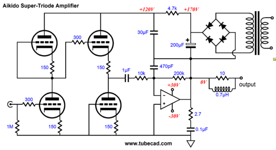
Just where do you find a 120V battery? Basically, you don't; instead, you can build up a simple high voltage power supply that will function much like a high voltage battery.
I know it looks confusing. Part of the problem lies in the way I drew the schematic (a wider schematic would be handy). Additionally, I added the 470pF feedback bypass capacitor to increased stability. This capacitor should have appeared in most of the previous variations, but I wanted to show as naked, but still functional a topology as I could. Of course, one floating power supply per channel would be required, which is a pain. And of course, the PS-6 power supply could not be used. But my aim here was mind stretching. We can never be too flexanimus: flexibleness of mind or disposition.
Next Time //JRB |
I know that some readers wish to avoid Patreon, so here is a PayPal button instead. Thanks.
John Broskie
And
High-quality, double-sided, extra thick, 2-oz traces, plated-through holes, dual sets of resistor pads and pads for two coupling capacitors. Stereo and mono, octal and 9-pin printed circuit boards available.
Designed by John Broskie & Made in USA Aikido PCBs for as little as $24 http://glass-ware.stores.yahoo.net/
The Tube CAD Journal's first companion program, TCJ Filter Design lets you design a filter or crossover (passive, OpAmp or tube) without having to check out thick textbooks from the library and without having to breakout the scientific calculator. This program's goal is to provide a quick and easy display not only of the frequency response, but also of the resistor and capacitor values for a passive and active filters and crossovers. TCJ Filter Design is easy to use, but not lightweight, holding over 60 different filter topologies and up to four filter alignments: While the program’s main concern is active filters, solid-state and tube, it also does passive filters. In fact, it can be used to calculate passive crossovers for use with speakers by entering 8 ohms as the terminating resistance. Click on the image below to see the full screen capture.
Tube crossovers are a major part of this program; both buffered and un-buffered tube based filters along with mono-polar and bipolar power supply topologies are covered. Available on a CD-ROM and a downloadable version (4 Megabytes). Download or CD ROM
|
|||


| www.tubecad.com Copyright © 1999-2011 GlassWare All Rights Reserved |