| John Broskie's Guide to Tube Circuit Analysis & Design |
14 August 2005 Radiotron Designer’s Handbook
It’s all true enough, but I wish he had written “even though their low output impedance and low distortion appear attractive,” as rp isn’t the same as Zo. Moreover, I would argue that he isn’t altogether right about the cathode-follower output stage not stabilizing the grid bias, as all output transformers hold primaries with relatively high DCR, which acts as a simple cathode-bias resistor and makes even a fixed-biased cathode-follower output stage, a quasi-cathode-biased one. For example, where a fixed-bias, EL34-based amplifier might need –35V to set the output tubes’ idle current, those same EL34s in a cathode follower output stage amplifier might only require –15V to set the same idle current, as the primary’s wire resistance acts as a cathode resistor that displaces 20 volts. And while I must agree that the cathode-follower output stage makes huge demands on its driver stage, I believe that we can extract all that is desirable from this topology without introducing further problems—if we are both careful and clever, that is. For example, as was mentioned in the last blog entry, solid-state rectifiers make adding extra power supply rails easy, which wasn’t true when the Radiotron was written. These added power supply rail voltage can be negative or a multiple of the main B+ voltage. In either case, the increased usable voltage can be put to good use. Since the driver stage spans the negative to the positive rail, it has twice the voltage available to it than does the output stage, which allows for the needed big voltage swings, but it also adds the problem of power-supply noise spilling into the output. The output stage itself rejects much of the B+ noise at its plate; however, if the power-supply noise is presented to its grid, then it will be relayed along with the music to the loudspeaker. Now in this bipolar power supply amplifier, if the driver tube and its cathode resistor’s combined effective impedance equals that of its plate load resistance, the noise will null at the driver stage’s output, as the positive rail noise is out of phase with the negative rail’s noise and the driver stage effectively defines a 50% voltage divider. Thus, 50% of +1 to –1 is 0. This desired condition is met when the plate resistor equals (mu + 1)Rk + rp, with the cathode resistor left unbypassed. 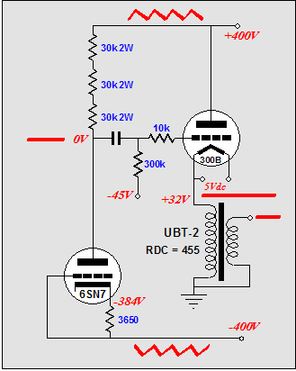
Well, it will null if the driver stage’s grid is terminated into the negative rail; otherwise the power supply noise will leak through or, worse, be amplified. Imagine that the grid is “grounded” to ground via a coupling capacitor. In such a case, the driver stage constitutes a grounded-grid amplifier with the negative-power-supply rail noise acting as its input signal. 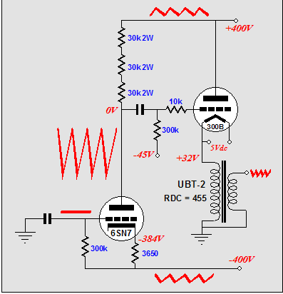
The common-cathode amplifier’s two cathode resistors are so arranged to provoke an in-phase image of the negative power supply rail noise on the common-cathode amplifier’s output. This is accomplished by bypassing the larger-valued resistor with a large-valued capacitor, which effectively imposes all of the negative rail noise into an unbypassed cathode resistor, which in turn imposes the negative rail noise at the input stage’s output. How? Since the top cathode resistor is effectively half the value of the plate resistor, the noise current will develop twice the noise signal in the plate resistor. However, as the plate resistor terminates into the noisy positive rail, half of the negative-power-supply noise will be cancelled, leaving 100% of the negative power supply noise for the driver tube’s input. 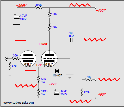
Is the common-cathode amplifier the only topology that allows us to inject the negative power supply rail noise into its output? No, as several other topologies can be “fixed” to achieve the same end, starting with the insanely ubiquitous grounded-cathode amplifier. (Imagine that this topology were made illegal; what would 90% of tube gurus do?) 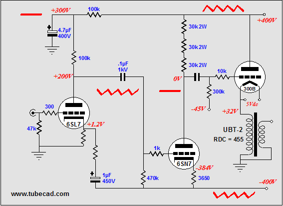
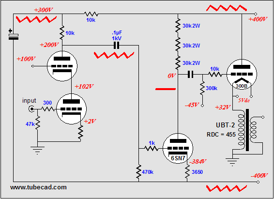
Alternatively, we could use a cascode input stage. Normally, the cascode is rightly viewed as having an appallingly low PSRR figure—in fact, virtually none. But in the totality of the entire amplifier circuit, this liability becomes an asset. All we have to do to exploit the cascode’s poor PSRR figure is terminate its plate resistor into the negative rail, not the positive B+ nor ground. As shown below, almost all of the negative rail noise will appear at the cascode’s output.
Using a pentode-based input stage, with the same power supply decoupling, would also yield the desired result. One practical problem all of the topologies will face is that the negative power supply rail will not be taxed nearly as much as the positive rail will be, as the positive rail must feed the input, driver, and output stages; while the negative rail will only feed the first two. In other words, we can reasonably expect more noise on the positive than the negative power supply rail. Thus, some tweaking will be needed; for example, smaller filtering capacitors on the negative rail. Next time //JRB |
Tube CAD does the hard math for you. This program covers 13 types of tube circuits, each one divided into four variations: 52 circuits in all. Tube CAD calculates the noteworthy results, such as gain, phase, output impedance, low frequency cutoff, PSRR, bias voltage, plate and load resistor heat dissipations. Which tube gives the most gain? Tube CAD's scenario comparison feature shows which tube wins. Windows 95/98/Me/NT/2000/XP
For more information, please visit our Web site : To purchase, please visit Antique Electronic Sales' website: |
|||


| www.tubecad.com Copyright © 1999-2004 GlassWare All Rights Reserved |