| John Broskie's Guide to Tube Circuit Analysis & Design |
| 30 April 2009
Alan Dower Blumlein’s garter circuit appeared here before, in blog 46. This is a simple, cross-coupled, four-cathode-resistor-current-balancing circuit. But before I jump into circuits, I have a digression to follow. Once again, the female readers of this blog—all three or four, maybe even five—keep me in line. Great was the temptation to use an illustration of a garter-belt adorned beauty, rather than create the silly image above. Very great indeed. Like most men, I find garter belts on women alluring beyond justification or logic. Justification? Nowadays, garter belts are seldom justified because silk and nylon stockings are seldom worn. Logic? There is something altogether illogical or paradoxical about how adding a small black garter belt can make so dramatic an increase the seductiveness of already unclothed women, considering that the garter belt neither supports nor obscures anything of prurient interest. Victoria was not only secretive, but obviously correct, as some clothing is certainly more than no clothing. In addition to my deference to the sensibilities of my female readership, I am inclined to think that Blumlein named his “garter circuit” not after the sexy, lacey little numbers worn by enticing women, but those dreary tiny garter belts worn below each knee by male characters in Monty Python sketches and by Prince Charles; alas.
Back to circuits, John Atwood asked if I had any more information on Blumlein’s garter circuit, which I didn’t, but he did plant a renewed interest in me concerning the circuit. To quickly recap, the garter circuit strives to equalize the idle current drawn by both output tubes. Why is this goal worth pursuing? Transformer-coupled, push-pull power amplifiers most often use gap-less output transformers to limit output transformer size and maximize output power. These transformers cannot withstand very much unbalanced current flow before they saturate, greatly reducing power output and greatly increasing distortion. Eliminating a net unidirectional current flow through the primary is thus a worthwhile goal. Blumlein’s circuit does do a fair job of establishing equal conduction between output tubes, but it does so at the cost of lost B+ voltage and wasted heat generation. My modern updates on his circuit were shown in blog 46 and were meant to make small improvements to his garter circuit. To this end, I employed DC servo loop, current mirror, long-tailed differential amplifier, and even a single-transistor differential amplifiers to force balanced current conduction by making one output tube draw the same current as its mate. No doubt some are wondering why any fancy circuit is needed as they always use matched tubes. The short answer is that even matched tubes are not that matched—being only matched at one cathode-to-plate voltage and one idle current—and that matched tubes can fall out of balance as they age.
Leaving the cathode resistor bypass capacitors out of the following schematic(s) for clarity's sake, here is the Blumlein garter circuit.
The more I thought about Blumlein’s circuit, the more I realized that my efforts were fundamentally different, albeit in a subtle way. Where his garter circuit cross-coupled the output tubes, thereby cross referencing the DC operating points between output tubes, my designs all used a follow-the-leader approach, wherein one output tube played master and the other slave. In other words, Blumlein’s circuit was more egalitarian. The more current-hungry output tube worked to encourage its spindly companion to conduct more and, at the same time, the current abstemious tube also restrained its greedier partner. The garter circuit averaged, the high were brought down, the low were raised. My efforts, however, equalized: if the master tube ran hot, both ran equally hot; if the master tube ran cool, both ran equally cool. In addition, Blumlein’s circuit offers the nice feature of extra safety, as its averaging approach means that if one output tube is removed, the other halves its current conduction in response. In contrast, my circuits are a bit like those airplane stunt pilots that follower the leader in perfect formation into a crash. (Well, not a real crash with the tubes.) For example, what if one output tube were pulled from the socket with my circuits, specifically the master output tube, then the slave tube would see its DC grid voltage plummet, as the auto–correct circuit would strive to turn off the slave tube. Not bad. But if the slave tube were pulled from its socket, the auto–correct circuit would crank up the missing tube's DC grid voltage in an attempt to get the missing tube to conduct, which could cause trouble if the tube were re-inserted while the amplifier was powered. Not good. Why would anyone pull an output tube from a live amplifier? Imagine a faulty tube socket and an intermittent contact. On the other hand, imagine what would happen if one output tube arced and shorted (this is very rare indeed) or, what is much more likely, one output tube going gassy, causing much too high an idle current. With the garter circuit, the good-working tube would only see half the DC voltage present on the failing tube's cathode. In contrast, my auto–correct circuits might even more grossly over bias the slave tube. Averaging seems the better approach, although I did include a few voltage limits in my previous designs. A third approach, by the way, would be to establish which output tube was conducting least and then bring its overexuberant companion down to its level; leveling, in other words. (The temptation to quote Søren Kierkegaard is more than I can withstand, "Leveling at its maximum is like the stillness of death, where one can hear one's own heartbeat, a stillness like death, into which nothing can penetrate, in which everything sinks, powerless," from his The Present Age. Although this quote has really nothing to do with this circuit, I expect that his book will soon be rediscovered, just as had been during the late 1970s, and for many of the same reasons.) How to proceed? Like Blumlein’s garter circuit, our new effort must cross reference each output tube, since we want both tubes to conduct the average of their unfettered conduction. And we should strive for the simplest, most robust design possible.
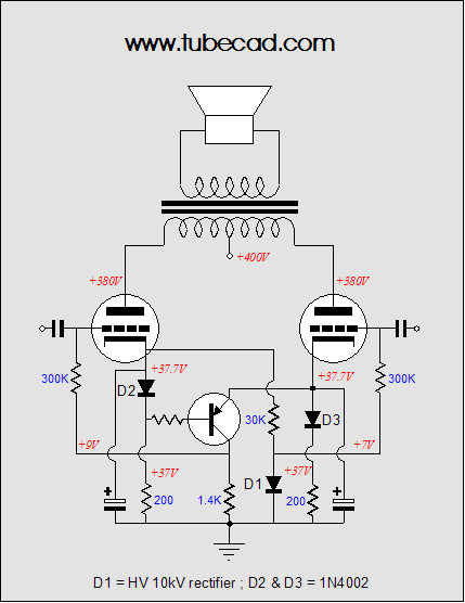
The above circuit looks promising, as it only uses two transistors and a handful of parts. This circuit simply doubles up on the following circuit.
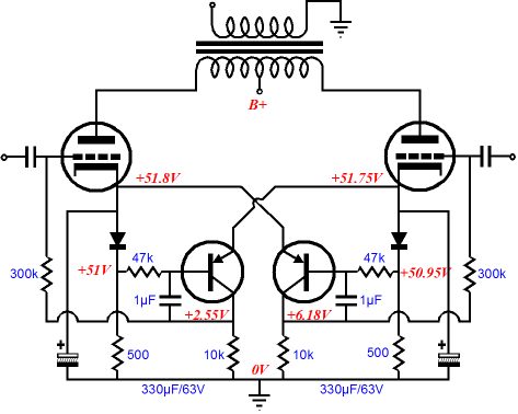
Let’s add the missing cathode resistor bypass capacitors, just to help those who don’t bother to read the text. (You do not know who you are, as you are not reading this sentence, but I will know who you are when you e-mail me asking where the bypass capacitors are.)
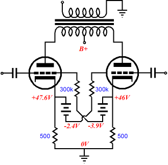
(And yes, these capacitors can and should be bypassed by quality film capacitors.) The circuit is simple enough. Each transistor’s emitter sees its reference voltage at the opposing tube’s cathode and each transistor’s base gets its DC error voltage from the bottom of a silicon diode. (The diodes impose a countervailing DC voltage drop that helps make up for the emitter-base voltage differential.) Like the plate in a triode, the transistor’s collector will move in the opposite direction than its base moves; in other words, the collector inverts the base’s phase. Thus, if the base sees a lower voltage than the emitter sees, the collector will pull up on its load resistor, creating a more positive grid-bias voltage for its output tube. If the output tube conducts too much, the base will effectively see a positive-going signal voltage that will cause the collector to release some of its current conduction, causing the grid-bias voltage to drop. Negative feedback, in other words. Because both transistors are working at once, they will average the current conductions. By the way, the DC voltages shown in the above schematics were taken from some SPICE simulations I performed on the circuits; I used a 300B SPICE model and a hacked version of the same SPICE model that lessened its conduction a tad, so I could simulate mismatched tubes. The transistors can be a high voltage devices, such as the MJE350, but need not be, as the transistors should never see too high a voltage, just as the cathode resistor bypass capacitors should never see high voltage. Expensive, high voltage 1µF capacitors are also not needed, as they pass no AC signal to the output tubes. I know that a few readers will be troubled by the PNP transistors. (Solid-state is creepy enough, but PNP is even creepier.) Well, the circuit could be turned on its head and NPN transistors could be used, but at the expense of reduced resolution. Speaking of reduced resolution, one thing that troubled me about the garter circuit was that it effectively threw away half of the error signal by using two large-valued cathode resistors in series per output tube. These resistor pairs created 50% voltage dividers, so 50% of the error signal was lost. This prompted me to think of some workaround that would retain the entire error signal. The following circuit shows a garter circuit variation that uses two 50V batteries. The batteries would never be used in a real power amplifier, but they are useful for evaluating the design concept.
The two batteries didn’t provide better performance over the original Blumlein garter circuit; in fact, this variation was slightly worse creating a larger disparity in conduction. (Why show this circuit then? First, it is valuable to know where not to travel. Second, it is something of a trap for those who don’t read the text, as they might assume that the last circuit is the best circuit.)
//JRB
|
E-mail from GlassWare Customers
High-quality, double-sided, extra thick, 2-oz traces, plated-through holes, dual sets of resistor pads and pads for two coupling capacitors. Stereo and mono, octal and 9-pin printed circuit boards available.  Aikido PCBs for as little as $24 http://glass-ware.stores.yahoo.net/
Only $19.95
Download or CD ROM www.glass-ware.com
|
|||


| www.tubecad.com Copyright © 1999-2009 GlassWare All Rights Reserved |