| John Broskie's Guide to Tube Circuit Analysis & Design |
29 October 2018 Post 444
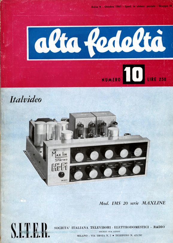
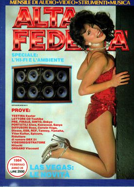
Alta Fedeltà What caught my attention was all the sonic control on display. Each channel gets its own treble and bass controls; a shared stereo volume and balance control; rumble filter and high-frequency notch filter, with selectable frequencies; an input signal selector; and, lastly, but most interestingly, a sonic presentation mode control, which allowed the user to choose between stereo or mono or just left or right channel signals. That is a lot of sonic control. Well, in this issue, I discovered at least two interesting circuits. The first of which was a loudspeaker crossover that required bi-wiring, as it used two different impedance taps on an output transformer, so that a 16-ohm tweeter could be used with an 8-ohm woofer.
The crossover is a second-order type with a crossover frequency of 4kHz. I showed similar crossover designs in post 394. The second interesting schematic belonged to an integrated stereo tube-based power amplifier. The maker was apparently Stereophonic and the model was their "Dynamic."
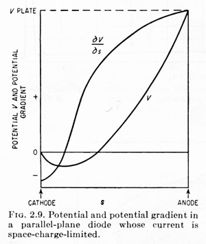
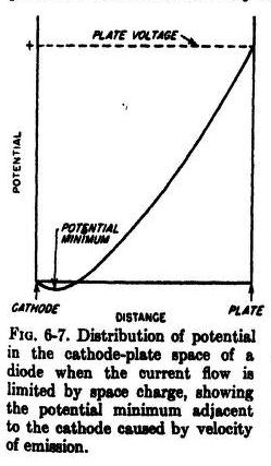
Click on schematic to see enlargement Yes, there is a lot going on here, most of which we will ignore. A few quick highlights worth pointing out are the use of two EZ81/6CA4 rectifiers and a non-center-tapped high-voltage secondary, which is impossible. No doubt this is just a schematic typo. With a grounded center-tap, the two tube rectifiers effectively create a full-wave, center-tapped rectifier circuit. Second, note the absence of cathode resistors for tubes V1a, V1b, V2a, V2b. What is going on here? How do the triodes bias up correctly? The answer is found in the 10M grid resistors and input coupling capacitors. If we could remove the casing from a carbon-composition resistor and measure the voltage gradient across the carbon slug that bridges a 100V power supply terminal to ground, we would see zero volts at one end and 100 volts at the other end; and across the surface we would measure a linear voltage rise from 0V to 100V. Now, imagine that we could place voltage probes inside a triode and measure the voltage gradient from the cathode to plate, while the triode was placed across the same 100V power supply.
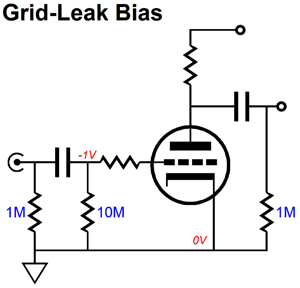
From Electronics Designer Handbook, Page 2-12 At the cathode, we would measure 0V; at the plate, 100V. But the voltage would not linearly move from that 0V to the 100V; instead, we see the voltage drop negatively as we move away from the cathode and then the voltage would climb positively until we hit the plate and read 100V. What is happening inside the triode is that electrons are boiling off the hot cathode and being attracted to the positive plate voltage. Not all the electrons make it to the plate, however, as those lacking sufficient velocities of emission will form a space-charge* cloud of electrons above the cathode, which limits the current flow to the plate. The space charge is slightly negative relative to the cathode, so that the freed electrons with the lowest velocity will be repelled by the negative charge and fall back into the cathode. Now, should we leave the grid free floating, attaching to nothing, the grid will become negatively charged, possibly so much so that current flow to the plate ceases altogether. On the other hand, if we attach a high-ohmage grid resistor, say 10M in value, to the grid and place a coupling capacitor in front of the grid resistor, we can maintain a fixed negative bias voltage on the grid, as the high-resistance resistor will prevent the grid from becoming excessively negatively charged. An electronic free-bee of sorts, which is known as grid-leak biasing.
Grid leak biasing requires that non-leaky coupling capacitors and low-level input signals, as the circuit is prone to blocking distortion, which arises when the grid draws positive-grid current and the coupling capacitor becomes negatively charged, but can only slowly discharge due the the large-valued grid resistor. If the coupling capacitor becomes excessively negatively charged, the grounded-cathode amplifier may cease amplifying altogether, as the triode has become cut-off and no longer conducts any current. The advantage to grid-leak biasing is that no cathode and no bypass capacitor are needed. Well, if small input signals are best, would this biasing method be best suited to phono preamps? No. On page 489 of the Radiotron Designer's Handbook states:
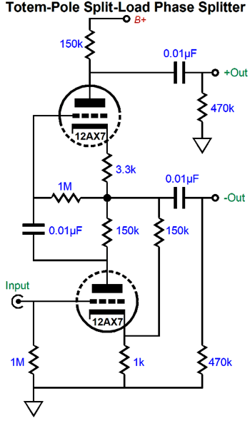
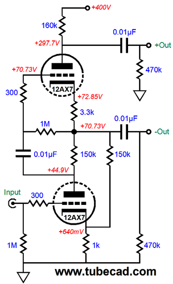
The next and final interesting aspect of this amplifier circuit is the power amplifier input stage and phase splitter, which in this design is an in-line totem-pole layout, wherein the split-load phase splitter sits atop the grounded-cathode amplifier.
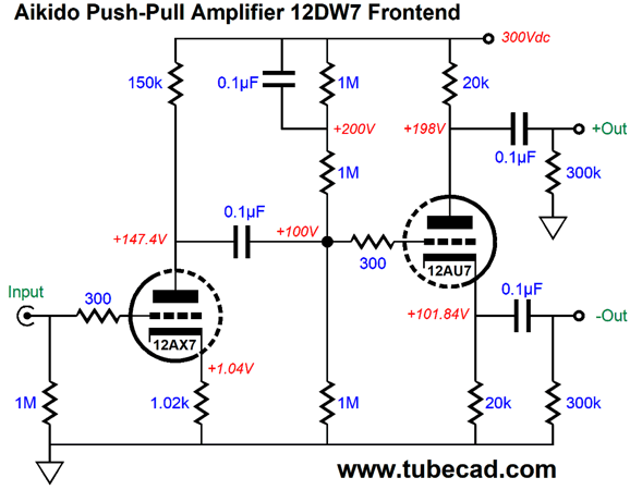
The bottom 12AX7 triode is configured as a simple grounded-cathode amplifier that develops inverting gain at its plate. The output signal at the plate then travels through the 0.01µF internal coupling capacitor to the top triode's grid. The top triode's cathode follows this signal in phase at its cathode, which creates an active load impedance for the bottom triode's plate. The 150k plate resistor for the bottom triode effectively gets magnified to far greater resistance, mu times greater. It is as if the bottom triode was loaded at its plate by a constant-current source. In addition, the top triode develops a varying voltage drop and varying current flow through the extra 150k resistor to the right, which will be relayed through the top triode to the top 150k plate resistor. The result is an inverted signal at the top triode's plate, equal in magnitude to the output signal at its cathode. If this added 150k resistor were not there, we would not get anything useful from this push-pull front-end circuit. The secret to understanding this topology is found in grasping that the top triode draws more current than the bottom triode, it has two current paths to ground, one through the bottom triode and one through the 150k resistor. (Back in 2000 and again in post 226 I showed a L+R and L-R circuit that used a similar approach. It fundamentally differs in that, in my circuit, both top and bottom triodes draw the same idle current, as I included an additional capacitor.) The extra 150k resistor to the right does not terminate into ground, as we might have expected, but into the bottom triode's cathode. Why? Positive feedback. Had the 150k resistor terminated into ground the gain would fall to about 95; but by terminating into the cathode, the gain climbs to 200, twice the 12AX7's amplification factor (mu) of 100. The SPICE model of the 12AX7 that I used presents a mu of 95 and plate resistance of 55k at an idle current of 1mA and 100V cathode-to-plate voltage. Most positive feedback schemes fail. Why? Although the gain goes up, which in turn increases the amount of negative feedback employed; but as the distortion usually goes up as well, the result is no net improvement. Here is analogy: one spouse steals from the other spouse, so the household net worth remains unaltered. So my expectations were not high. I was surprised, however, to find no real increase in distortion, but a large improvement in gain. By the way, I did make one small modification to the original circuit by increasing the topmost plate resistor value to 160k to improve the balance between phase splitter outputs.
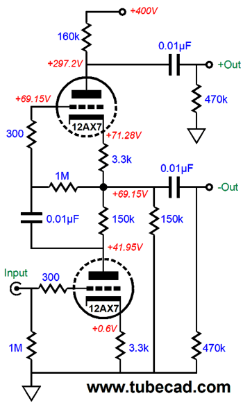
Now let's compare the no-positive feedback version with the one above.
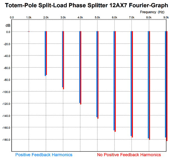
Note the larger cathode resistor value, which was required to restore the cathode voltage to the previous value. Next, we will compare the distortion from both version in SPICE simulation. The non-positive-feedback version saw an input signal of 0.25Vpk at 1kHz, while the positive-feedback version saw an input signal of 0.Vpk; both developed a peak voltage swing of 20V from each phase output.
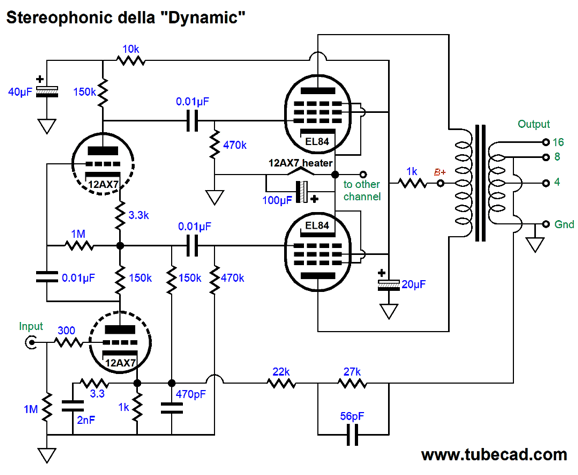
Basically no difference worth bothering about. Okay, let's now look at the entire power amplifier circuit.
Do not panic; it's not nearly as complex as it appears. We will follow my practice of starting with the end of a power amplifier and working our way back to the input. The output stage is transformer-coupled and holds two 6BQ5/EL84 pentodes that are run as pentodes, not triode-connected or ultra linear. The four output tube cathodes all attach together, which requires using a matched quartet of output tubes. In place of a cathode resistor, a 12AX7 heater element is used. This not only saves having to use a power resistor it allows us to get a free DC heater voltage for one input tube. If we want, we could place a zener diode in parallel with the heater element, along with its bypass capacitor. The EL84 grid-2 all attach together to a 10k resistor to the B+ voltage and 20µF capacitor to ground. The phase splitter attaches to the output pentodes through 0.01µF coupling capacitors and each pentode gets a 470k grid resistor. Oddly enough, no grid-stopper resistors are used anywhere; not a good idea. A negative feedback loop attaches to the output transformer secondary (the schematic shows a conflict, as the 16-ohm is used in one channel, but the 8-ohm tap is used in the other channel; in other words, we see a schematic typo) and terminates in the bottom 12AX7's cathode. The 1k cathode resistor then attaches to a complex capacitor-resistor network that compensates for phase shifts from the circuitry and output transformer. The part values used here depend on the output transformer used. The gain from the power amplifier stage is surprisingly high, which we deduce from the negative feedback resistor values (33k and 27k in series) and the 1k cathode resistor. This leads me to believe that the feedback must be taken at the 16-ohm taps, not the 8-ohm taps. All in all, an interesting integrated amplifier design.
More Split-Load Phase Splitters
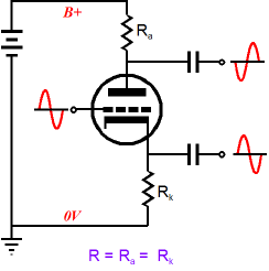
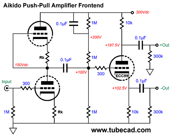
The totem-pole arrangement creates a grounded-cathode amplifier with an active plate load. The gain equals half the triode's amplification factor. This input stage functions as 50% voltage divider to the power-supply noise at the B+ voltage connection and ground. A coupling capacitor then sends the signal to the split-load phase splitter. The three 1M resistor in series deliver a third of the B+ voltage to the phase splitter's grid. Thus, with a B+ voltage of 300V, the grid will see a DC voltage of 100V. Now, the 100V might prove to high in value, if bigger output signal voltage swings are required from the phase splitter. With the one-third B+ voltage divide, the split-load phase splitter's triode and plate and cathode resistors all see the same DC voltage drop, which intrinsically results in an asymmetrical maximum output signal. For example, with the 300V B+ voltage, the bottom output can swing negatively by 0V, but only 50V positively; conversely, the top output can swing negatively by only 50V, but 100V positively, as the triode's 100V cathode-to-plate voltage drop sets hard limits. In post number 167, I give the solution to the maximum symmetrical output swing from both outputs:
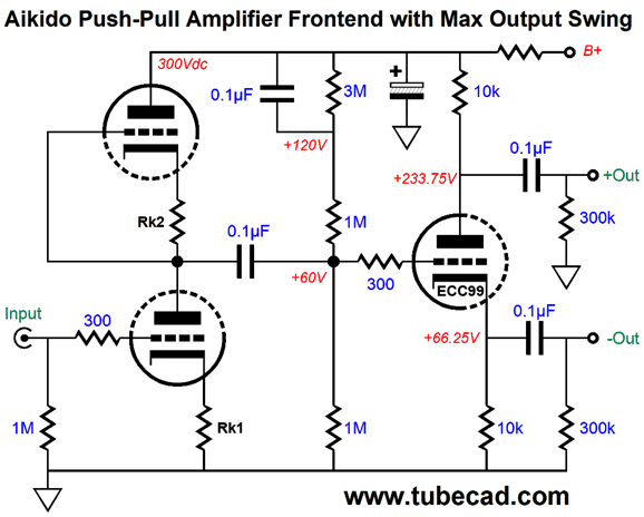
The missing step is to take the optimal idle current value and multiply it against the cathode resistor value to find the optimal voltage drop across the cathode and plate resistors at idle. The ECC99 provides a plate resistance of about 2300 ohms. Plugging this resistance and the 300V B+ voltage and the resistor value of 10k into the formulas, we get 6.1mA as the optimal idle current and 61V as the optimal voltage drop across the cathode and plate resistors. Thus, the optimal B+ voltage division would result in 19% of the B+ voltage presented to the split-load phase splitter's grid. Let's round up to 20% and replace the top 1M resistor with a 3M resistor, which will deliver 20% of the 300V B+ voltage to the ECC99's grid.
The resulting voltages were derived from a SPICE simulation. With this rearrangement, we could easily get over +/-50Vpk swings from both outputs. On the other hand, the previous version with the one-third B+ voltage split will result in lower distortion, but with smaller peak symmetrical output swings. Each version would find its best fit, depending on the rest of the circuit. Note the added RC filter at the B+ voltage connection. Ideally, there would be no power-supply noise. Invariably, there is, albeit very little in some of the best circuits. In addition, bear in mind that power-supply noise can come from two different sources: the rectification ripple and the varying current in the audio circuit. In other words, the audio signal itself can induce power-supply noise, unless the B+ voltage connections offers zero impedance, which is unlikely if not impossible.
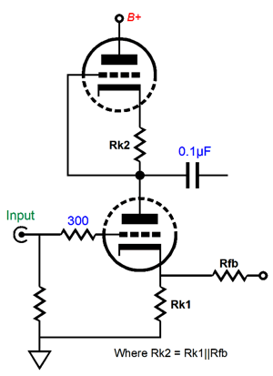
Another point worth mentioning is that if a negative feedback loop terminates in the bottom input triode's cathode, that feedback resistor will effectively be in parallel with the bottom cathode resistor, Rk1. In this situation, the top cathode resistor, Rk2, value must match the parallel value of the bottom cathode resistor. Another—but less obvious—subtlety is that the assumption has been that the split-load phase splitter triode delivers unity gain at its cathode. In fact, no triode can. In other words, we actually need to present a tad bit more than 50% of the power-supply noise to the split-load phase splitter's grid. This means that we should make the top cathode resistor, Rk2, slightly lower in value. How much less depends on the triodes used. We will have arrived at the right value, when we achieve the best PSRR figure. We can make a single tube Aikido push-pull front-end with a 12DW7/ECCC832, which is a dual triode tube whose triodes are dissimilar, with one being a 12AX7 type and the other a 12AU7 type.
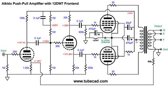
In SPICE simulations, the above part values resulted in the best performance. We can add an output stage that injects 50% of the power-supply noise at the output tubes cathodes, which will further improve the amplifier's PSRR.
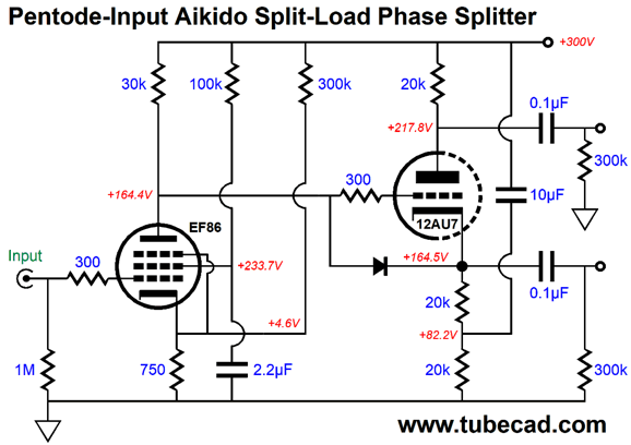
Note that the 12DW7 heater element is bypassed by the same valued capacitor that attaches to the B+ voltage. Of course the heater bypass capacitor voltage rating need only be 16V, while the second 470µF capacitor should be rated for 350V. (Not shown, but should have been, is a 12.6V zener in parallel witht he heater. If the input tube were missing from its socket, the two 470µF capacitors would strive to split the B+ voltage; not good.) What happens if we use a pentode as the input tube, rather than a triode? We get a lot more signal gain and the PSRR drops to near zero at the pentode's plate. This means that both of the split-load phase splitter outputs must present 100% of the power-supply noise and in phase. The following schematic shows how we can reach this goal.
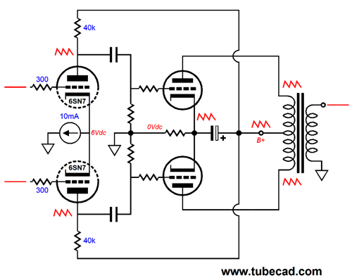
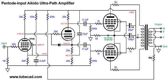
Note the 300k resistor that bridges the EF86's cathode to the B+ voltage. It introduces a small portion of the power-supply noise to the cathode, which increases the power-supply noise at the pentode's plate. The next item to note is the extra 20k cathode resistor on the split-load phase splitter. This resistor allows us to DC couple the pentode stage to the phase splitter and, with the 10µF capacitor to the B+ voltage, injects 100% of the power-supply noise at the bottom of the 20k cathode resistor above it. In other words, the split-load phase splitter is nested in a world of 100% power-supply noise, as its cathode, grid, and plate all see 100% of the power-supply noise. The result is that each phase splitter output contains the same portion of power-supply noise, which the output tubes will largely ignore. In fact, this arrangement allows us to create an optimal setup, wherein the output tubes see a bypass capacitor that attaches to the cathode and terminates into the B+ voltage. Think of it as Ultra-Path for a push-pull output stage. I have shown this arrangement many times before, the last time being in post 430 from this year. Here is a schematic from that post
A differential amplifier is used as an all-in-one input and phase splitter stage, which offers a PSSR of zero. But as the output tubes see 100% of the power-supply noise at their cathodes and plates, seeing 100% at their grid only makes things better, as the power-supply noise drops out of the equation. Ideally, the output tubes would be biased by a constant-current source, which would help ensure 100% of the power-supply noise appearing at the cathodes. The downside to the constant-current source is that the output stage must be run in class-A.
Above, we see a complete power amplifier. Note that the EL84 output tubes are being run as pentodes, which means that we must use a negative feedback loop to both reduce the distortion and output impedance. On the other hand, if the output tubes were triode-connected, we might be able to forgo the feedback altogether—or at least use much less of it. In either case, less gain would be needed from the input stage. For example, the 12DW7 could be replaced by a 12AY7 or 12AT7.
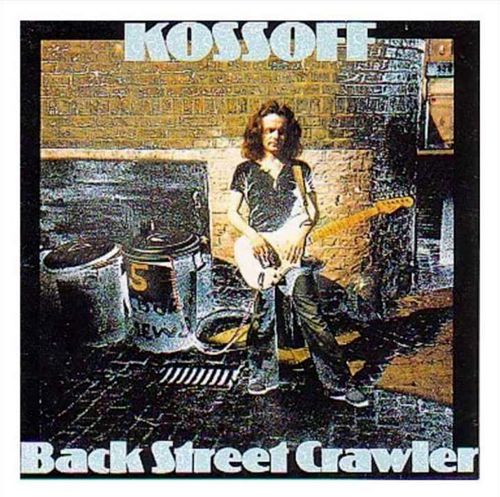
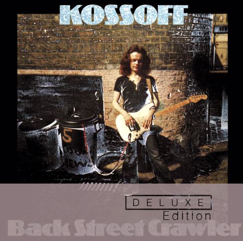
Music Recommendation: Paul Kossoff's Back Street Crawler
Well, Tidal offers a deluxe version that holds 20 tracks and plays for over two and a half hours! Mercy. Far more than I could have hoped for. If you are a fan of blues/rock guitar, definitely give this album a listen.
//JRB
* Alta Fedeltà in the 1980s
*Space Charge
User Guides for GlassWare Software Since I am still getting e-mail asking how to buy these GlassWare software programs:
For those of you who still have old computers running Windows XP (32-bit) or any other Windows 32-bit OS, I have setup the download availability of my old old standards: Tube CAD, SE Amp CAD, and Audio Gadgets. The downloads are at the GlassWare-Yahoo store and the price is only $9.95 for each program. http://glass-ware.stores.yahoo.net/adsoffromgla.html So many have asked that I had to do it. WARNING: THESE THREE PROGRAMS WILL NOT RUN UNDER VISTA 64-Bit or WINDOWS 7 & 8 or any other 64-bit OS. One day, I do plan on remaking all of these programs into 64-bit versions, but it will be a huge ordeal, as programming requires vast chunks of noise-free time, something very rare with children running about. Ideally, I would love to come out with versions that run on iPads and Android-OS tablets.
//JRB |
Special Thanks to the Special 69!
I am truly stunned and appreciative of their support. In addition I want to thank
All of your support makes a big difference. I would love to arrive at the point where creating my posts was my top priority of the day, not something that I have to steal time from other obligations to do. The more support I get, the higher up these posts move up in deserving attention. Only those who have produced a technical white paper or written an article on electronics know just how much time and effort is required to produce one of my posts, as novel circuits must be created, SPICE simulations must be run, schematics must be drawn, and thousands of words must be written. If you have been reading my posts, you know that my lifetime goal is reaching post 1,000. I have 556 more to go. My second goal is to gather 1,000 patrons. I have 931 patrons to go. Help me get there.
The Tube CAD Journal's first companion program, TCJ Filter Design lets you design a filter or crossover (passive, OpAmp or tube) without having to check out thick textbooks from the library and without having to breakout the scientific calculator. This program's goal is to provide a quick and easy display not only of the frequency response, but also of the resistor and capacitor values for a passive and active filters and crossovers. TCJ Filter Design is easy to use, but not lightweight, holding over 60 different filter topologies and up to four filter alignments: While the program's main concern is active filters, solid-state and tube, it also does passive filters. In fact, it can be used to calculate passive crossovers for use with speakers by entering 8 ohms as the terminating resistance. Click on the image below to see the full screen capture.
Tube crossovers are a major part of this program; both buffered and un-buffered tube based filters along with mono-polar and bipolar power supply topologies are covered. Available on a CD-ROM and a downloadable version (4 Megabytes). |
||


| www.tubecad.com Copyright © 1999-2018 GlassWare All Rights Reserved |