| John Broskie's Guide to Tube Circuit Analysis & Design |
|
22 April 2007
Teflon coupling capacitors I have three different brands of Teflon-based coupling capacitors to experiment with. I have tried them all, but I do not use them. Why? Although they each can do certain things better than any other coupling capacitor, overall they sound wrong. I mentioned this to my friend Chris and he told me that I probably hadn’t given them enough of a break-in period. I asked how long that should take; his reply was sometimes months. To make things even worse, he pointed out that each time they are re-energized, they must undergo a mini-break-in period, sometimes lasting an hour or so. Well, I do not have the time or the patience for such recalcitrant capacitors, so they languish in my part pin. One thought I have had is that while all coupling capacitors seem to go through a brief warm-up period, this period is obvious and painfully long with Teflon coupling capacitors. What to do? What if the Teflon capacitor is never discharged? Would it require any break-in or warm-up time? The Aikido amplifier can readily accept a full-on B+ voltage, with the heaters left cold. Because all the triodes must conduct to complete the major current paths through the tubes (no cathode-stripping problems) and because the safety resistors will set the correct voltage relationships without the tubes even being used, the coupling capacitors can continue to see a steady DC biasing voltage, while the Aikido rests in a standby mode. When we are ready to listen to music, the heaters can be connected to their power supply and the triode will commence conducting. This technique could be used with other types of coupling capacitors and maybe beneficially so. This experiment would be easy to implement and the results just might prove quite satisfying.
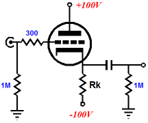
More No-Gain—No-Pain So what is required to make a good tube-based unity-gain buffer? For most tube fanciers, the immediate answer is to use a cathode follower. This solution makes a lot of sense, as the cathode follower offers no gain and both a low output impedance and distortion figure. A cathode follower, however, isn’t the only circuit that will work as a buffer. For example, the plate-follower also provides unity-gain, a low output impedance and distortion figure. But I am jumping ahead too much. Instead, let’s start with the cathode follower, a very simple cathode follower at that.
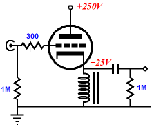
Since the greatest voltage swing that a unity-gain buffer might be expected to undergo is only 2Vpk, the above circuit will work surprisingly well. The trick is to use a high plate voltage and a low-mu triode, say a 12B4 or 5687 or 6BX7 or triode-connected EL84 or EL86. A triode’s mu (its amplification factor) is the measure of the grid’s ability to override the plate in controlling the conduction of current. For example, a triode with a mu of 10 holds a grid that is ten times more effective than its plate in controlling the flow of current through the triode, so that 100V at the plate can be countered by -10V at the grid—in theory, killing all current flow. Thus, if 250V is applied to the plate, then -25V will turn off the triode and a -12.5V grid voltage will place the triode at the midpoint between cutoff and positive-grid voltage (0V). Now the 12.5V of possible voltage swing can readily handle the 1V to 2V of output voltage swing that the unity-gain buffer might be required to pass. So what we have is a truly simple cathode follower that only requires four resistors and one coupling capacitor as supporting parts. If you require a tube buffer for your CD player, this simple circuit might be all that you need. In that case, stop reading, break out the soldering iron, and get to work. For the rest of us, including the individual who is seldom satisfied with simple solutions, several modifications to this simple circuit are possible. For example, the cathode resistor can be replaced by a choke, with relatively high DCR, which will serve as a cathode resistor in DC terms, but function as a constant-current source in AC terms. In fact, a choke will allow output voltage swings in excess of the grid-to-cathode voltage, allowing the builder to use relatively high-mu triodes, such as the 6N1P.
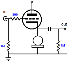
Another possibility is to replace the cathode resistor with a constant-current source. (In the latest AudioXpress magazine, the justly famous Walt Jung has written an excellent article on designing and building solid-state constant-current sources.)
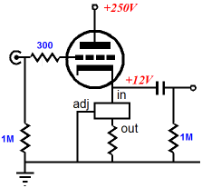
A discrete constant-current source can be made from FETs or transistors or ICs. In fact, a fairly good constant-current source can be made from just one three-pin voltage regulator and a resistor, as shown below.
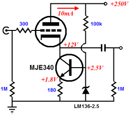
The LM317 is available in the D²-PAK package, which will fit under a tube socket, so as to hide the incriminating solid-state evidence ;) To set the idle current, just find a resistor equal to 1.24/Iq, for example 10mA requires 1.24/0.01, which equals 124 ohms. Of course, many would prefer to opt for something much more expensive, such as the LT1085. Regardless of the regulator used, be sure to observe the maximum voltage differential across the regulator. (It might be prudent to place a zener—rated at some voltage slightly lower than the maximum regulator voltage—across the constant-current source.) On the other hand, when using MOSFETs and transistors, high-voltage versions do not cost much more than low-voltage types, so use an MJE340 instead of a MJE200.
Another modification to the simple cathode follower is to give it a negative power supply, which will allow a much larger cathode resistor to be used, which, like the constant-current source, will help linearize the cathode follower.
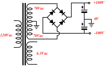
I know that many solder-slingers hate negative power supplies passionately, but as center-tapped secondaries are common on high-voltage power transformers, extracting a negative potential is a breeze (if you are wiling to use solid-state rectifiers).
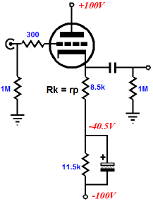
Now, we can apply an Aikido trick. The cathode follower does a good job of rejecting power supply noise present at its plate, but not a perfect job. Once again, mu is key, as the cathode follower’s PSRR is roughly equal to 1/mu, when a single positive power supply is used. With a bipolar power supply, the math gets a bit more complex. Assuming that the positive and negative power supply rails share an equal magnitude of noise voltage, differing only in 180-degree phase reversal, some of the positive-power-supply rail’s noise will leak through to the output. On the other hand, if the triode’s plate resistance equaled the cathode resistor’s resistance, the two power supply rails’ noise would null at the cathode follower’s output. In this case, let’s specify that Rk equals rp and be done with such subtleties; unfortunately, this will not work, as the idle current will prove far too high, equaling the conduction at zero grid voltage. The workaround is to use two cathode resistors, one bypassed, and the other equal to rp.
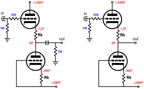
Yes, the large-valued electrolytic capacitor is icky. True, the resistor and bypass capacitor could be replaced by a zener, but zeners are also icky (a tube voltage reference, on the other hand…). The easy solution is to balance the cathode follower with a triode-based virtual cathode resistor, in other words, the same triode.
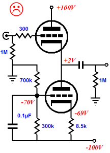
Since top and bottom triodes present the same AC resistance, and since the two power supply rails hold equal and anti-phase noise, the output of this buffer sees no power supply noise, just as the center of a stretched rubber band does not move. Wait a minute, how did that top cathode resistor sneak into the circuit? I want the lowest output impedance possible. Do you really? Why? If your answer isn’t the need to drive 32-ohm headphones, I doubt that the added resistance will severely truncate the bandwidth or weaken the buffer’s ability to drive 20k-input-impedance solid-state amplifiers. If we remove the top cathode resistor, then we must remove or bypass the bottom cathode resistor, which brings us back to too much idle current or icky zeners or electrolytic capacitors. On the other hand, the added, small-valued cathode resistor will help linearize the cathode follower’s output and buffer the top cathode from the crippling capacitance presented by long interconnects. Use the cathode resistor; trust me. (The version on the right above offers DC coupling at the output, which is probably safe enough when driving a tube power amplifier, but is scary as hell, when driving solid-state amplifiers. One giggle and the woofers could be doing pushups against the facing wall.) Well, since we have added a second triode, why not create a closer approximation to a constant-current source? In the circuit below, the top triode works into a near constant-current source, as the unbypassed cathode resistor’s resistance is magnified by the mu of the bottom triode.
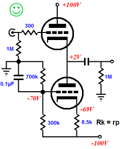
The exact formula for the total impedance presented by the bottom triode’s plate is: Z = rp + (mu + 1)Rk For example, given a 6SN7 with a mu of 20 and a the 8.5k cathode resistor, the total effective resistance becomes 187k, which would require a negative power supply voltage of 935V, if a 187k resistor were used in its place. Why the unhappy face? This circuit holds a major problem. Can you spot it? If you cannot, do not feel bad as 99.9% of tube fanciers can’t either. In fact, the layout is textbook, but textbooks are often wrong. Shunting the bottom resistor of the two-resistor voltage divider with a bypass capacitor results in about a 1/mu reduction of power supply noise at the output. On the other hand, shunting the top resistor instead results in about a near-infinite reduction of power supply noise at the output, if the cathode resistor equals the triode’s rp.
As I have about three times more to say on this topic, it is best to save some for next time. //JRB |
Support the Tube CAD Journal & get an extremely powerful push-pull tube-amplifier simulator for TCJ Push-Pull Calculator
TCJ PPC Version 2 Improvements Rebuilt simulation engine *User definable
Download or CD ROM For more information, please visit our Web site : To purchase, please visit our Yahoo Store:
The Tube CAD Journal's first companion program, TCJ Filter Design lets you design a filter or crossover (passive, solid-state or tube) without having to check out thick textbooks from the library and without having to breakout the scientific calculator. This program's goal is to provide a quick and easy display not only of the frequency response, but also of the resistor and capacitor values for a passive and active filters and crossovers. TCJ Filter Design is easy to use, but not lightweight, holding over 60 different filter topologies and up to four filter alignments: While the program’s main concern is active filters, solid-state and tube, it also does passive filters. In fact, it can be used to calculate passive crossovers for use with speakers by entering 8 ohms as the terminating resistance. Click on the image below to see the full screen capture.
Tube crossovers are a major part of this program; both buffered and un-buffered tube based filters along with mono-polar and bipolar power supply topologies are covered. Available on a CD-ROM and a downloadable version (4 Megabytes). Download or CD ROM
|
|||


| www.tubecad.com Copyright © 1999-2007 GlassWare All Rights Reserved |