| John Broskie's Guide to Tube Circuit Analysis & Design |
20 July 2009
I was in such a hurry to listen to the octal All-in-One that I forgot to take a picture of the assembled board prior to loading it into a chassis. In fact, I accidentally posted a picture of the CCDA board in its place to the GlassWare Yahoo store.
Well, after a happy month of listening to the octal All-in-One, I broke out the soldering iron and removed from its case.
As you can see in the picture above, the octal All-in-One is running the new Russian Tungsol 6SN7s. I have bought and sold a lot of these tubes, which makes sense as they are much better than other current-production 6SN7s. But for my own equipment, I have been using NOS 12SX7 tubes, which I like a great deal. Well, I decided to try the Tungsols in the CCDA board I built up and I was surprised by how good they sounded, better than I remembered them sounding when I first heard them two years ago. Now I do not know if the original Tungsols I heard were subpar or whether the new production has gotten better or both. Sadly, I only have about a dozen Tungsols left and I must wait before I make another huge order, so I have decided to sell half of my own NOS GE 12SX7s stock of tubes. If only the new Tungsol factory could be convinced to make a true 12SX7 (and 6GM8/EE86/6N27P), we would all benefit.
Split-Load Phase Splitter & Zo
Many argue that its lack of voltage gain is an obvious nonstarter or that its limited voltage swings are too restrictive or that its dissimilar output impedances present a real engineering problem that can only be resolved by adding a build-out resistor to the cathode’s output to increase its output impedance, making it match that of the plate output. If you are a long-time reader of the Tube CAD Journal, then you know that I simply do not believe in absolute circuits, that I argue that a circuit only succeeds in varying degrees at different tasks, that an obvious circuit failing in one application can prove a golden asset in another application. The seemingly perfect headphone amplifier may prove close to perfect with high-impedance headphones, but sound embarrassingly weak with low-impedance headphones. So, before we can pass judgment on the split-load phase splitter, we must first know what it is being asked to do. It’s not enough to ask how good the split-load phase splitter is as a phase splitter, as we need more information before we can evaluate its success. For example, someone might want a line-stage amplifier with a switchable output phase.
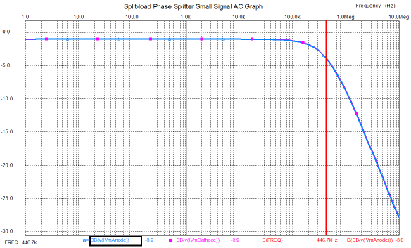
I love the concept, as a three-position rotary switch allows the ear to readjust during the slight pause with the mute in the middle position, which makes discerning changes in phase much easier. Unfortunately, this line-stage amplifier holds a flaw: the dissimilar output impedances, with the non-inverting output at the plate presenting a much greater output impedance that the inverting output at the cathode. And, yes, the split-load phase splitter is at fault. Imagine a solid-state power amplifier with an input resistance of 20k and the phase set to non-inverting. The amplifier will see a smaller signal voltage, as the 18k or so of output impedance presented by the second triode’s plate is effectively in series with the 20k input resistance, so about half of the potential signal will be lost. If the switch were set to inverting, then the power amplifier input signal would jump in magnitude, as the about 1200-ohm output impedance presented by the cathode results in a much smaller attenuation of the signal. Now, adding a build-out resistor in series with the cathode’s output will undo the imbalance in signal strength by reducing the cathode output’s to match the plate’s output. Cable capacitance and the power amplifier’s own input capacitance adds to the complexity. For example, just 1000pF of load capacitance will drag the split-load phase splitter’s frequency response down at high frequencies, starting at about 16kHz. Of course, different tubes and different plate and cathode resistors will give different high frequency cutoffs. Nonetheless, in this application, the split-load phase splitter lets us down. (This is why I used a cathode follower after the split-load phase splitter in my Circuit-of-the-Month design back in 1998.)
Birds of a Feather Must Flock Together
It is something of a miracle how well this works in practice, as long as the idle current is sufficient to charge and discharge the load capacitance quickly enough, otherwise slew limiting will occur—not a good thing.
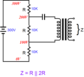
Zo and Split-Load Phase Splitters Conversely, a perfect current source presents an infinite output impedance and infinite voltage swing, while maintaining a fixed output current. Driving an output with a current source will develop a varying voltage between output and current source. Placing a voltmeter at the connection allows us to directly read the voltage swings. For example, forcing an output to swing 1A peaks, will induce peak voltage swings equal to I x Zo. Assuming a 10-ohm output impedance, we would see 10V swing between voltage source and output. Great, but where do we find a close approximation to an ideal current source? We could build a voltage-to-current convertor circuit that would look a lot like a big, heavy power amplifier—or we could use a transformer and a coupling capacitor.
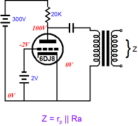
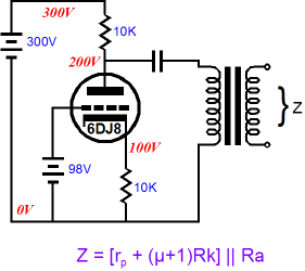
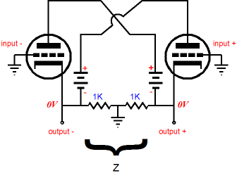
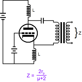
The schematic above shows how an isolation transformer and a large-valued coupling capacitor can be used to test the split-load phase splitter output impedance differentially. For example, if the transformer’s secondary was driven by a voltage amplifier, then we would measure the current flow through the connection to the voltage amplifier; or, if a voltage-to-current convertor were attached to the secondary, we would measure the voltage swing at the connection (or at the plate and cathode). (Note how the ground symbol was left out of the schematic. Why? Ground takes on an exaggerated importance in many a solder slinger’s mind; he imagines ground as being something akin to a superhero, capable of performing amazing feats, such as passing many amperes of current through thin PCB traces without developing any concomitant voltage drops. Seeing ground as a metaphysical category, not as a circuit’s reference point, the cult of ground is both widespread and devoted. So, it’s best to leave ground out of the picture.)
No controversy here; the triode presents a AC resistance equal to its rp, its plate resistance (which is usually much lower than its effective DC resistance); and the plate resistor presents its fixed value to the transformer’s primary. Because the power supply presents a dead short, in AC terms, the triode’s rp is effectively in parallel with the plate resistor, so the parallel AC resistance is the output impedance of this circuit. No doubt the following circuit will cause some head scratching, but it is functionally no different from the more conventional cathode follower output configuration that follows it.
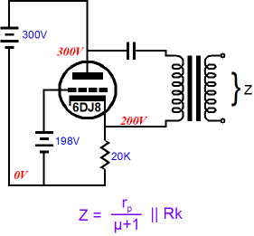
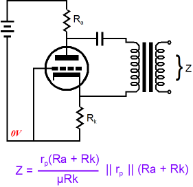
The cathode follower output presents a low output impedance because the triode’s grid remains locked and forcing the cathode up or down in voltage will result in the triode’s transconductance to buck such voltage movements. For example, forcing the cathode more positive will work to decrease the triode’s conduction, thereby compelling a negative-going tug by the current flowing through the cathode resistor. And forcing the cathode more positive will further increase the triode’s conduction, compelling an upward pull by the triode. Still no controversy. Now let’s thicken the stew a bit. In the following circuit, we see a grounded-cathode amplifier with an unbypassed cathode resistor. The output impedance at the plate can no longer be the plate resistance in parallel with the plate resistor; instead, it must include the addition brought by the naked cathode resistor, as this resistor undermines the triode’s transconductance, which in turn increases the triode’s effective plate resistance. Note that both the plate and cathode resistors share the same value, which makes this circuit look very split-load phase splitter-like. This also means that we have the output impedance formula for the split-load phase splitter inverting output at the plate, when presented with an unbalanced load. (With most high-mu triodes, the output impedance is close to the plate resistor’s value.)
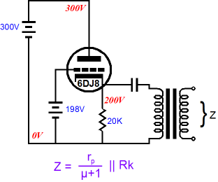
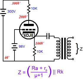
Adding an unbypassed plate to a cathode follower also increases the cathode follower’s output impedance.
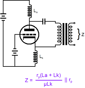
Note how the plate resistor, Ra, effectively adds to the triode’s rp. Also note that once again both the plate and cathode resistors share the same value, which once again makes this circuit look very split-load phase splitter-like. This also means that we have the output impedance formula for the split-load phase splitter noninverting output at the cathode, when presented with an unbalanced load. Note that the cathode output offers a much lower output impedance to an unbalanced load. Yes, I know that the two above circuits were not being used as proper phase splitters and that the two outputs were not given equal loads. Sometimes life just isn’t fair; nonetheless it’s well worth knowing how these circuits behave. So far, only a smidgen of controversy. Now let’s return to the split-load phase splitter with a balanced load.
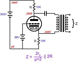
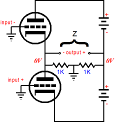
In the above formula, the 2R portion is easy to explain, as it represents the plate and cathode resistors being effectively in series with each other, which the following schematic might help illustrate.
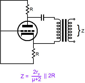
In the above schematic, we have eliminated the power supply, as it was effectively a dead short to AC signals. Now, we clearly see that both resistors are in series with each other. We also see that the grid sees the midpoint between these two resistors, which helps explain why the 2rp term appears in the formula. For example, if the cathode is forced 0.5V more negative and the plate is forced 0.5V more positive, the grid will see the null between the plate and cathode movements, so the cathode only moves half the voltage that a cathode in a cathode follower circuit would move. Thus, only half of the triode’s transconductance can be summoned to buck the applied 1V external disturbance. In other words, half of the triode’s kick is lost because, relative to the cathode, the grid is only seeing half of the imposed voltage. And since a triode’s transconductance is equal to its amplification factor over its plate resistance, the 2rp and (µ+2) terms reflects the halving of available transconductance. This halving of transconductance also happens in a Circlotron amplifier, which explains why its output impedance is higher that offered by what look like balanced cathode followers.
And long-time TCJers will remember this Circlotron equivalent circuit from the Cars, Planes, and Circlotron article, which also slpits the the applied voltage before delivering it to the grids.
Of course, the two amplifiers shown above could never be biased correctly with their grids grounded. The schematic's aim was to show the placing of the reference point (ground) at the center of the load's terminals. For example, in the amplifier shown above, if the ground had been located at the junction of the two batteries, then the grids would see the full externally applied voltage, rather than the half it sees with the midpoint grounding arrangement. If all of this seems too thick and your head is beginning to hurt, don’t worry, as we will backtrack a bit now.
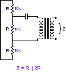
Back to Split-Load Phase Splitter Basics So here is an interesting idea. What if we eliminated the plate and cathode resistors? What if we replace both resistors with inductors, not real chokes with DCR, but idealized inductors with zero voltage displacement due to their zero DCR?
Now the plate and cathode resistors fall out of the equation and we are left with only twice the plate resistance divided by (µ + 2). Once again, the grid will see only half of the externally applied voltage, so only half of the triode’s transconductance can be summoned to counter the applied voltage. (The inductors form a voltage divider much as two resistors do.) But what if the inductors differed in value? What would the output impedance be?
If inductor La is set to 0H, then the grid will see the entire applied voltage across the triode, provoking the full wrath of the triode’s transconductance, which will buck the applied voltage due to increased or decreased current flow through the triode. Conversely, setting Lk to 0H will lock the grid to the cathode, eliminating any changes to the grid-to-cathode voltage, so only the triode’s rp will fight the applied imposed voltage change. By the way, just in case the || symbol is confusing you, it stands for placing two numbers in parallel; thus, X||Y = XY/(X + Y). And if we place an infinite number in parallel with a finite number, like the triode’s rp, we end up with the finite number, in this example, the triode’s rp. And zero placed in parallel with any number results in zero. But as real split-load phase splitters do not use inductors (although they could, and the real choke’s DCR could function like a cathode resistor in setting the idle current), we need to return to the resistor-laden version of the split-load phase splitter. And we need a formula for the case wherein the plate and cathode resistors differ in value.
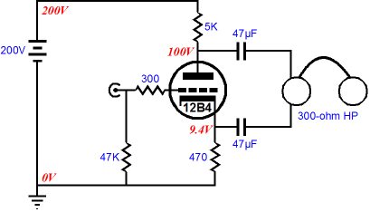
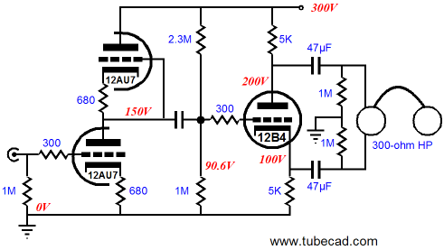
Why would anyone build a split-load phase splitter with dissimilar load resistors? Here is one possibility: a balanced headphone amplifier where the cathode resistor is needed to set the idle current. Of course, the voltage swing at the cathode output is only about a tenth of that at the plate, so the output is not balanced relative to ground; but as far as the headphones are concerned, it is.
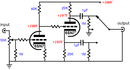
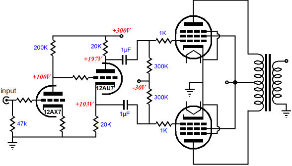
Understand that I am not recommending that someone build this headphone amplifier. I repeat, I am not recommending it. Why? The output impedance would prove too high and headphones would see the voltage difference between the cathode and plate voltages, about 45Vdc, which scares me greatly. But the real point to this exercise was that our universal formula is there when we need it. If I were to design a split-load phase splitter-based headphone amplifier, it would look something like the following, as I would want to use my Aikido techniques to null the power-supply noise from the outputs. (In this example, half of the power-supply noise will appear at each output, so the headphone element effectively cannot see the power-supply noise.)
Overview of the split-Load Phase Splitter
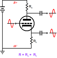
Split-Load Phase Splitter’s Achilles Heel So, can you spot the dissimilar load in the following schematic?
You don't see it, do you? Yet it is plainly there…or is it? The problem partially lies with the pentode’s graphic symbol, as it could include more information. Well, since the symbols we have are the symbols we will always have, I will redraw the schematic to make the imbalance more obvious.
Wait a minute --where did the extra diodes and resistors come from? The answer is that they were always there, implicit in the tube’s workings. Why does a triode or pentode plate collect electrons from the cathode? The cathode emits electrons because it is hot; the plate (anode) accepts and beckons the free electrons because it is a more positive voltage relative to the cathode. If the plate is at a voltage negative relative to the cathode, no conduction occurs, which is how tube rectifiers work. Now what happens when the grid becomes more positive than the cathode? It conducts current from the cathode, much in the same way that the plate does. When the grid is more negative than the cathode, as it usually is in most tube circuits, it does not accept the cathode’s freed electrons, which is what gives the grid its ultra-high input resistance. Because positive grid voltages are rare, we tend to ignore and forget that the grid and cathode define a diode. So now the imbalance is laid bare. Under large signal excitation, one grid can be driven into conduction, while the other is safely negative relative to its cathode. Imbalance. Now each of the split-load phase splitter’s outputs alternately sees high and low impedance, thereby throwing the phase splitter’s balance off and adding lots of distortion. Of course, if you never clip your power amplifiers, this will not be a problem that you might face. On the other hand, most audiophiles play their music very loud (why else would there be audiophiles and why else would demo records sell so well—do you really believe that anyone wants to hear the 1812 Overture again or listen to upright pianos being dropped on their backs).
SPICE
Time to Stop
//JRB
|
E-mail from GlassWare Customers
High-quality, double-sided, extra thick, 2-oz traces, plated-through holes, dual sets of resistor pads and pads for two coupling capacitors. Stereo and mono, octal and 9-pin printed circuit boards available.  Aikido PCBs for as little as $24 http://glass-ware.stores.yahoo.net/
Support the Tube CAD Journal & get an extremely powerful push-pull tube-amplifier simulator for TCJ Push-Pull Calculator
TCJ PPC Version 2 Improvements Rebuilt simulation engine *User definable
Download or CD ROM For more information, please visit our Web site : To purchase, please visit our Yahoo Store:
|
|||


| www.tubecad.com Copyright © 1999-2009 GlassWare All Rights Reserved |