| John Broskie's Guide to Tube Circuit Analysis & Design |
|
Post 233 14 June 2012
The normally bright Colorado sky dims. A brown haze hovers in each direction. I sneeze upon returning from walking the dog. The dog wakes me in the night with his hacking coughs. Friends have fled their homes. The mountains abound with dry dead trees. Rain would be salvation. The fire burns on. It will do so for months. Everyone is nervous.
DACs & Tubes The topic isn't how to make a DAC out of tubes, but how can tubes receive the audio baton from the DAC. Once a DAC has converted its digital input signal into an audio signal, either in the form of a varying current or a varying voltage, the tube must convert the DAC's audio output into a useable voltage signal that can drive the power amplifier to full output. If the DAC's audio output signal is in the form of varying current, then the tube(s) must perform a current-to-voltage conversion. Many current-out DACs put out a peak current swing of 1mA, which must be transformed into at least 1V of peak output voltage by the tube circuit. An ideal I-to-V converter would present an input impedance of zero ohms and add no distortion to the output. With tube I-to-V circuits, the latter is the easier task, as low-impedance and tubes seldom go together. Is an ultra-low input impedance actually essential? Indeed, it is. A current-out DAC factors the extremely-low input impedance in its design, just as most audio circuits assume a clean, low-impedance B+ connection. Be sure to read TI's white paper on the topic by Ken Chan, Passive Termination for Current Output DACs. Thus, slapping a 1k load resistor on the current-out DAC's output pin just won't cut it. Why not? The DAC expects to see a fixed DC voltage at it's current output pin, not one that follows the varying current. Your ears will very quickly tell you that something is terribly wrong, as the sound will take on a turgid, slew-limited flavor. Well, couldn't we use a 10-ohm load resistor, which would only develop a 0.01Vpk voltage swing? This would certainly make the DAC happier, but it demands much greater amplification from the tube circuitry, as the 10mV signal must be amplified up to at least 1Vpk, a gain of 100 or +40dB. Not an impossible amount of gain, but an amount difficult to achieve with a single triode gain stage. For example, a 12AX7-based Aikido stage will yield a gain of only 50 or +34dB. In short, we need both a low input impedance and a high gain from our tube circuitry.
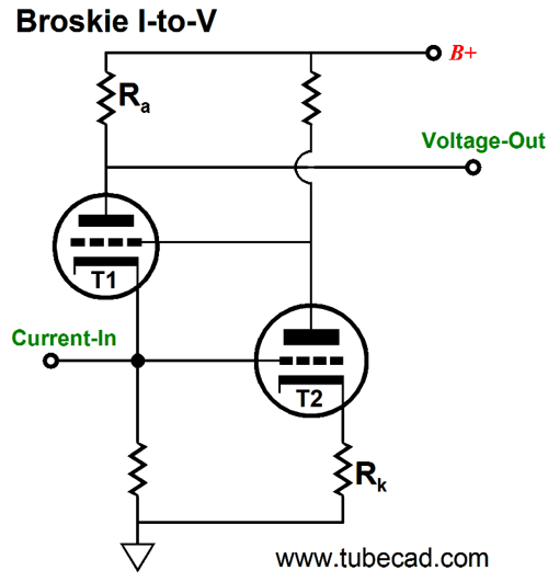
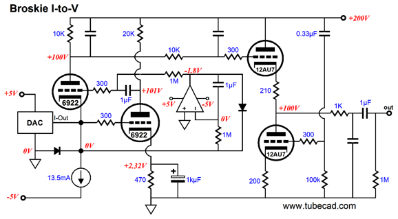
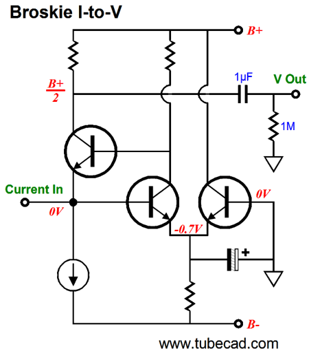
Broskie I-to-V
A varying current enters the circuit and develops a varying voltage as it encounters the resistor and the (T1) triode's cathode impedance in parallel with the resistor. This small voltage is then amplified at T1's plate. Simple enough. So what does triode T2 do? It sees the tiny voltage signal at its grid and then it amplifies it and inverts it, before delivering it to T1's grid. Since triode T1 sees an inverted signal at its grid, its cathode must follow the grid, so the input signal at its cathode must decrease substantially. So does the output voltage at T1's plate also decrease? No, somewhat paradoxically, it doesn't. Think in terms of current, not voltage. True the voltage signal a T1's cathode has decreased, but the voltage signal at T1's grid has greatly increased. In other words, triode T1 behaves much like a grounded-cathode amplifier with capacitor bypassed cathode resistor, which sees an input signal at its grid. As the grid voltage moves more positive, the current flow increases through the triode; as the grid voltages falls, so, too, the current. Here is a more fleshed-out version.
A high-transconductance triode should be used, such as the 6DJ8 or ECC99, as it will result in a lower input impedance. Speaking of Zin, how low an input impedance can we expect with this topology? In a simple grounded-cathode amplifier, the impedance at the cathode is equal to Zk = (Ra + rp)/(mu + 1) || Rk But in the Broskie I-to-V converter circuit, the input impedance is much lower due triode T2 working hard to keep the input voltage from varying. In other words, triode T2 defines the input stage of a negative feedback circuit sees any voltage signal at its T2’s grid as deviation from the signal at T2’s cathode, so T2 uses all its voltage gain to counter the unwanted grid signal. If triode T2 could summon infinite gain, the AC voltage across the input resistor would equal zero. Yet the DAC is putting out a varying AC current, so how can the input resistor see no change in current flow? A steady current flow through the input resistor is only possible when the T1 triode varies if current conduction in perfect sympathy with the DAC’s varying current output. For example, if the DAC draws an extra 1mA, triode T1 must draw 1mA less current; if the DAC draws 1mA less current, the T1 must draw 1mA more current. Now, if the load resistor sees a fixed voltage, what is the I-to-V converter’s input impedance? The answer is zero ohms. In a real circuit, with common audio tubes, such as the 6DJ8/6922/E88CC, the input impedance will be about 15 ohms. For such a simple tube circuit is amazingly low. (Note that lowest possible Zin would equal rp/mu² where the plate resistors were replaced with constant-current sources.) With I-to-V converters, we really should not speak of voltage gain, but of conversion ratio: the amount of voltage developed by a standard amount of input current, say 1mA. With the following Broskie I-to-V converter, the conversion ratio is about 9. In other words, if the DAC puts out 1mA of signal current, the I-to-V converter will put out 9Vpk of voltage signal. (Which implies a voltage gain of about 600, if you insist on looking at it that way. Note that highest possible gain would equal mu² where the plate resistors are replaced with constant-current sources.)
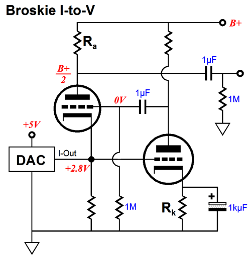
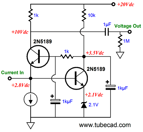
Please do not get hung up on the details, such as the AD1955 DAC or the B+ voltage or the tubes used. It is the topology—not the parts used—that is important. After attending the RMAF last year, I was intrigued by this DAC, although it is quite long in the tooth these days. The AD1955 puts out a varying current and it expects to see a fixed DC voltage at its output pin of 2.8Vdc. But different DACs have differing requirements. With a differential current-out DAC like the PCM1795 or PCM1798, we face the problem of the DC offset. The DAC expects to see 0Vdc and 0-ohms at its two outputs. In addition, the DAC draws an idle current of 3.5mA through its outputs. (This make using two load resistors problematic, as a pair of 100-ohm I-to-V resistors will each create a 0.35Vdc offset. At its peak current swing, the DAC will draw about 5.5mA, which against a 100-ohm resistor will equal 0.2Vpk of AC signal and 0.55Vdc of peak DC voltage; this may be far too much for the DAC to function. I have found from past experiments that about 60 ohms is high as I dare go with a current-out DAC, otherwise the dreaded, sleepy, slew-limited sound results.) So, how could such a DAC be used with the Broskie I-to-V converter? A low-voltage, power-supply rail is the answer.
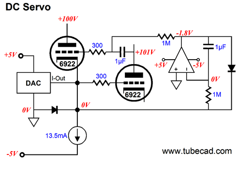
Why do we need a DC servo? Two reasons: the DAC must see 0Vdc at its output and it takes time before a tube is hot enough to conduct current. Ignore the two diodes for right now and note how the DC servo would work with hot triodes. The 1M resistor relays the voltage at the input to the OpAmp, which then compares the incoming DC signal with ground. If the DC voltage is positive, the OpAmp’s output will swing negative until the DC offset drops to zero. If the DC voltage is negative, the OpAmp’s output will swing positive, which will increase T1’s current conduction, thereby pulling up the input voltage to 0Vdc. Now, let's look into how the two diodes work. If the tubes are cold or missing from their sockets, then the diode that bridges ground and the I-to-V converter’s input will be forward biased and conduct, as the constant-current source will pull the I-to-V converter’s input negative. In other words, this diode will prevent the input from ever being more than about 0.7V negative. At the same time, the OpAmp will strive to bring the input voltage up to 0V by throwing its output positive. Once the OpAmp’s output goes over about 0.7V, the diode that bridges the OpAmp’s output and the I-to-V converter’s input will conduct, allowing the OpAmp to pull the I-to-V converter’s input up to 0Vdc. Yes, the OpAmp will have deliver 13.5mA into the constant-current source, but not for long. If the tube heats up or is returned to its socket, T1’s current conduction will provide the pulling up action and the two diodes will fall out of the circuit’s operation and the OpAmp will cease pulling up. Sweet.
DACs & Low-Pass Filtering
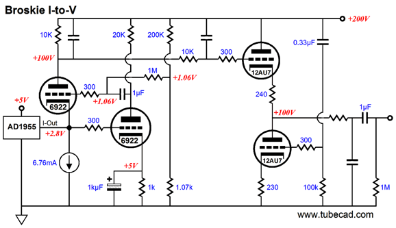
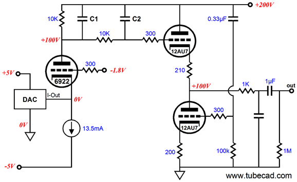
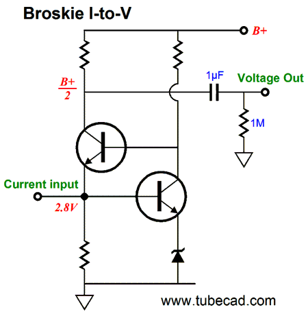
In other words, all of the power-supply noise is present on the plate. Why doesn’t off the same PSRR of a conventional grounded-cathode amplifier? The simple answer is that it is not a conventional grounded-cathode amplifier, but a compound amplifier made up from two conventional grounded-cathode amplifiers. The clever answer is that what feedback hath given, feedback hath taken away. In this example, negative feedback gave us an extremely low input impedance. Great, but at what cost? The price paid was a fantastically high output impedance at T1’s plate. Terminating capacitors C1 and C2 to ground would improve the PSRR at ultra-high frequencies, which we do not want. We don’t? Really? No, we do not, as we want the Aikido cathode follower to scrub away the power-supply noise from the audio signal it receives and terminating these capacitors to ground would only muddy the situation. Note how the bottom 12AU7 triode in the Aikido cathode follower sees all of the power-supply noise at its grid. It must, as the top 12AU7 also sees all the power-supply noise at its grid. Because the two 12AU7 triodes define a single current path from ground to B+, they function as differential amplifier of sort, which ignores com-mode signals at the two grids. Thus, if both grids see the same power-supply noise, it is not passed on at the Aikido cathode follower’s output. The added subtlety is the ever so slightly dissimilar cathode resistors used in the Aikido cathode follower stage, 210 ohms and 200 ohms. Why the difference? The bottom triode will see no power-supply noise at plate, but the top triode will see all of the power-supply noise at its plate. The noise at the plate will induce a small variation in current flow through the top triode, as it plate resistance and cathode resistor oppose the noise. To create the power-supply noise null at the output, either the bottom triode must see a greater amount of power-supply noise, which is impossible, as we are already 100%; or the top triode’s effective transconductance must be mitigated a tad, which the 10-ohm greater cathode resistor achieves. A triode’s effective transconductance with an un-bypassed cathode resistor is equal to With no cathode resistor or with a bypassed cathode resistor the formula reduces to the textbook definition of transconductance. gm = mu/rp I haven’t mentioned the first-order low-pass filter in series with output, as it optional. If further high-frequency filtering is required, this simple RC filter is a good solution, as it will filter away what little high-frequency grunge manages to get past the Aikido cathode follower. Solid-State Broskie I-to-V
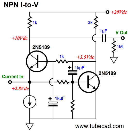
No coupling capacitors are needed, as the transistors can directly couple. The input load resistor can be replaced by a constant-current source and the collector resistor could be replaced by something fancy, such a current mirror or a folded cascode circuit. If the input needs to be at ground level (0Vdc), then the following circuit works well.
The added NPN transistor’s job is only to provide a needed voltage drop to keep the input ground centered. Because bipolar transistors offer such more transconductance than tubes, the amount negative feedback developed in this version is far greater. Thus, we might assume stellar performance. Well, I was disappointed with the results in SPICE simulations. Possibly the SPICE transistor model was inadequate or, more likely, transistors do not cascade in as complementary and harmonizing a fashion as triodes do. This led me to trying the following circuit, which is no longer a Broskie I-to-V converter, appearances to the contrary.
The above I-to-V converter is effectively just a single NPN transistor circuit, as the rightmost transistor is only part of an overly elaborate voltage reference. (This is a perfect example of a SPICE-induced circuit design, as it was born of laziness.) The following variation is a bit more coherent. It uses the rightmost NPN transistor’s base-to-emitter voltage drop as the voltage reference. By selecting different resistors values in the two-resistor voltage divider at the input we can set the desired input DC voltage offset.
Do not imagine that because I end with this circuit, it is the circuit I like best. It isn’t. The tube-based Broskie I-to-V converters are a much better choice. Remember, I have two aims: to show what is desirable and what is possible. By the way, if the DAC offers differential current outputs the Aikido cathode follower should be replaced by a Broskie cathode follower, which accepts a differential input signal and offers a good CMRR. This would require three dual-triode tubes, such as the 6DJ8, per channel. Next Time
//JRB |
|
I know that some readers wish to avoid Patreon, so here is a PayPal button instead. Thanks.
John Broskie
E-mail from GlassWare customers:
And
High-quality, double-sided, extra thick, 2-oz traces, plated-through holes, dual sets of resistor pads and pads for two coupling capacitors. Stereo and mono, octal and 9-pin printed circuit boards available.  Aikido PCBs for as little as $20.40 http://glass-ware.stores.yahoo.net/ Only $12.95 TCJ My-Stock DB
Version 2 Improvements *User definable Download or CD ROM www.glass-ware.com |
||


| www.tubecad.com Copyright © 1999-2012 GlassWare All Rights Reserved |