| John Broskie's Guide to Tube Circuit Analysis & Design |
|
17 January 2014
Evermore Circlotron Circuits
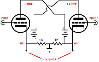
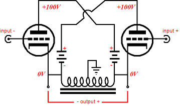
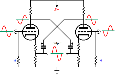
A quick recap: the Circlotron circuit is a supremely simple affair, which requires as little as two triodes, two floating power supplies, and two resistors. Yes, only six parts. (If we replaced the two resistors with a center-tapped choke, we would need only five parts!) Shockingly simple. Yet, this uncomplicated circuit befuddles many.
Of course, much more can and should be added. The two essential details are that this is a push-pull circuit (the triodes work in current anti-phase, in other words) and that two independent power supplies are not grounded (neither are grounded, finding their only path to ground through the two resistors); thus the ground falls mid load. This means that a stereo amplifier would require at least four independent, floating power supplies. This key point explains why I use the battery symbol in the Circlotron schematics, although a battery not likely to ever be used in an actual Circlotron.
(This might change in the near future, as a great deal of effort is being expending in creating cheaper, better high-voltage batteries for electric and hybrid cars. As it stands today, you can buy a 385V car batter for a little over $2,000. When the price drops to something closer to $200, we can expect to see many new battery-powered tube amplifiers.) If we use two output transformers, we can get away with a single power supply, even for stereo amplifiers.
Or we can use center-tapped inductors to archive the same goal of a single power supply. In either case, the two capacitors that cross-couple the plates and cathodes must be very large in capacitance. How big? With an 8-ohm load and 20Hz as the lowest frequency that must be passed, a 1kµF capacitor is needed in a simple RC filter. As both the output transformer and the multi-tapped inductor offer impedance magnification, the capacitor values can be much smaller. For example, with a reflected impedance of 800 ohms, a 10µF capacitors could be used.
If we are driving headphones, not loudspeakers, then we can use the following Circlotron variation that uses a single power supply.
Unlike the previous examples, this Circlotron must be run in strict class-A mode, whereas the other versions can be—and most certainly will be—run in class-AB. Why so? True class-A, unlike pseudo class-A that uses sloppy and leaky triode conduction at cutoff to claim class-A status, requires an insanely high idle current, if even a few watts are to be delivered to an 8-ohm speaker. For example, 16W of output into 8 ohms requires a peak output current swing of 2A, which requires an idle current of 1A per side in a Circlotron amplifier. In other words, a single channel of class-A, 16W Circlotron will draw 2A in its output stage. So, what the big deal? Divide 2A by the number of output triodes used. For example, if 8 triodes are used, then each triode must idle at 2A/8 or 250mA, which against a B+ voltage of 100V would create 25W of dissipation per plate, far beyond the 6AS7's plate limit. A 100W of output would require 5A of total idle current. Think about this, the theoretical maximum efficiency of a class-A output stage is 50%—something which you will never get in reality, using transistors or MOSFETs, let alone triodes. With triodes, we would be lucky to get 20% in an OTL. For example, in the 16W Circlotron OTL, the 2A of idle current against 100V of B+ voltage equals 200W of dissipation at idle, resulting in an efficiency of only 12.5%. In other words, even at that unattainable 50%, we would still see 200W of dissipation at idle and 100W into the speaker at full output. At the more realistic 12.5%... In the above circuit, the two electrolytic capacitors are assumed to be large in value, but they can never be infinite in value. As a consequence, they will begin to discharge when the output current exceeds twice the idle current one triode. No doubt, brief and occasional excursions will pass nicely, but heavy and sustained current immoderation will deplete the charge. Thus, music that exhibits a high dynamic range can play beyond the strict class-A limit, but organ and low-dynamic music (most modern pop music) cannot. Nonetheless, being able to get away with a single power supply, even with two channels, is a great benefit. On the other hand, if we are willing to give each channel its own power supply, then my following variation on the Circlotron offers many features.
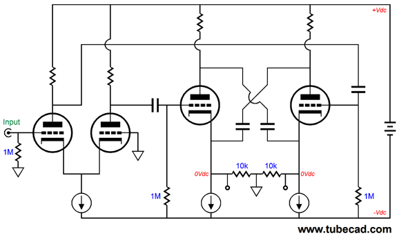
Three constant current sources are shown, but they each could be replaced by a simple resistor—at a slight decrease in performance. (The input stage's constant current sources is probably the most important of the three.) The assumption is that the cross-coupling capacitors that connect plate to opposing cathode in the output stage are very large in value, so that they approximate true floating power supplies. An added assumption is that matched pairs of triodes are used for the input and output stages, which explains why no output coupling capacitors are used. As can be readily seen, no global negative feedback loop is employed. Still, the output impedance is fairly low, being Zo = rp/(mu +2). For example, with an ECC99 output tube, an output impedance of a little over 100 ohms would result. If we want to use a global negative feedback loop, the sneaky way to do it is the following. Few see it, but it (or rather they) is still there.
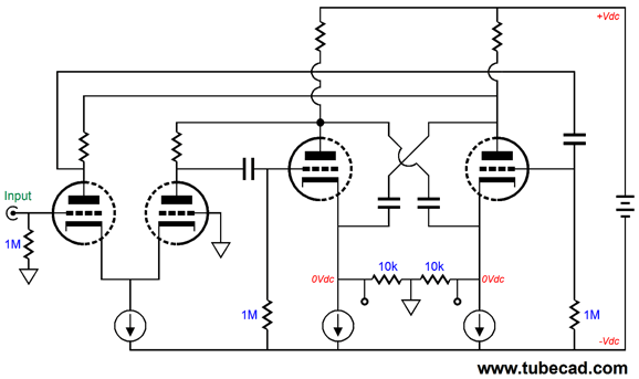
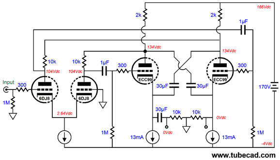
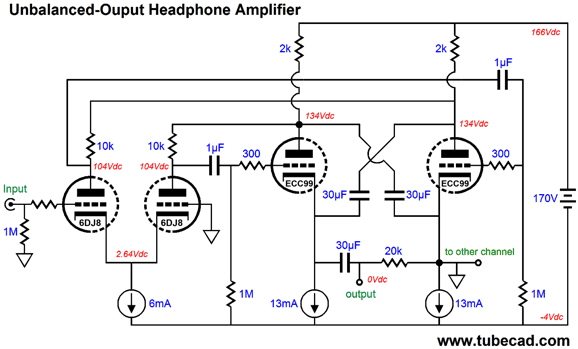
The differential input stage plate resistors terminate into the differential outputs, thereby creating two global negative feedback loops. To see how they work just image a battery being momentarily being shorted across the two outputs, which would cause one output to go positive, while the other goes negative. These two anti-phase pulses would then be relayed to the input stage and then passed on to the output triodes grids, provoking a counter reaction. Negative feedback in a nutshell. With an ECC99 output tube, an output impedance of about 80 ohms results. Now let's flesh out the topology and configure it to drive a 300-ohm load, such as the headphones made by Beyer and Sennheiser, such as the DT990 and HD800.
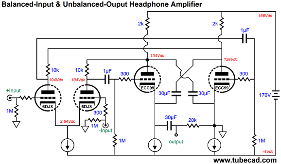
Each channel gets its own floating power supply. Interestingly enough, only one coupling capacitor is used. Although this headphone amplifier presents a balanced out, an unbalanced input signal is used. Or, we can switch thing around and use a balanced input and get an unbalanced output, as shown below.
I know that this circuit no longer looks like a circlotron, as the ground no longer falls mid load. So, strictly speaking, it is not a Circlotron. Yet, it functions much like the circuit before it. The same distortion and output impedance. The same peak voltage and current swings. Note how the two two global negative feedback loops have seemingly been replaced by a single loop, yet it functions effectively the same as the two did in the previous example, as it effectively now sees twice the output signal. What's going on here? The two floating power supplies, one per channel, is the answer. Without them, all the Circlotron-like qualities would vanish. What if we desire both an unbalanced input and output? If so, the following variation is what is needed. Each channel must get its own floating power supply and both channels must share a common ground connection.
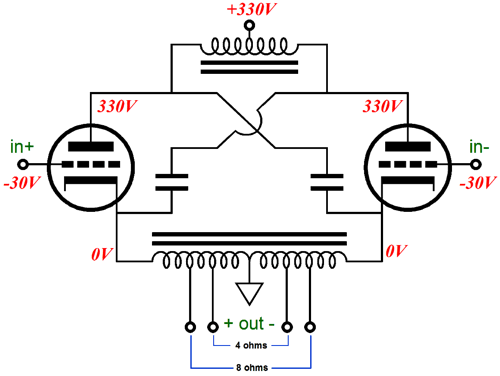
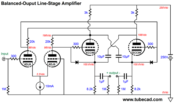
If lower impedance headphone are to be driven, an output transformer can be used; or, we could use several ECC99 tubes in parallel or different output tubes altogether, such as the 6AS7. Wait a minute, John, have you forgotten how much I hate headphones? No, indeed, no. For you I have the following balanced-output line-stage amplifier based on the same idea.
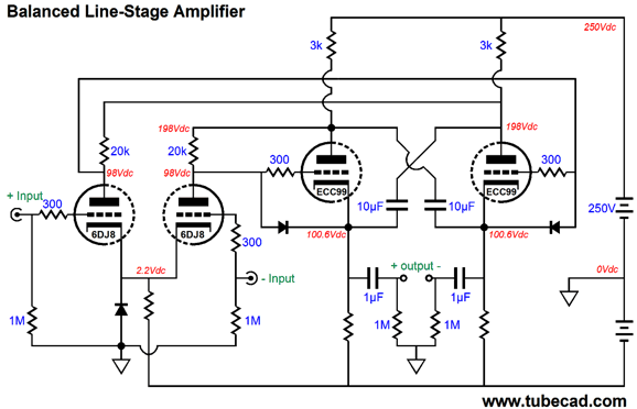
Note the higher B+ voltage; also note that a single fixed/grounded power supply can be used with both channels. Also note how we have lost the two internal coupling capacitors, as the output triodes now DC couple to the input stage, which explains why I added the two diodes to protect the output triodes at start-up. A nice circuit this. We could easily alter the circuit to accept a balanced input. If a balanced pair of input signals were used, we could forgo the differential amplifier's constant current source, making the circuit an all-tube design. Or, we could use a negative power-supply rail, which would restore much of the qualities bestowed by the constant current source.
The input stage now gets its own protection diode. Of course, other triodes could be used, such as 6SN7 and 12AU7 types. Next Time
User Guides for GlassWare Software
For those of you who still have old computers running Windows XP (32-bit) or any other Windows 32-bit OS, I have setup the download availability of my old old standards: Tube CAD, SE Amp CAD, and Audio Gadgets. The downloads are at the GlassWare-Yahoo store and the price is only $9.95 for each program. http://glass-ware.stores.yahoo.net/adsoffromgla.html So many have asked that I had to do it. WARNING: THESE THREE PROGRAMS WILL NOT RUN UNDER VISTA 64-Bit or WINDOWS 7 & 8 or any other 64-bit OS. I do plan on remaking all of these programs into 64-bit versions, but it will be a huge ordeal, as programming requires vast chunks of noise-free time, something very rare with children running about. Ideally, I would love to come out with versions that run on iPads and Android-OS tablets.
//JRB
|
|
Kit User Guide PDFs
Only $12.95 TCJ My-Stock DB
Version 2 Improvements *User definable Download or CD ROM www.glass-ware.com |
||


| www.tubecad.com Copyright © 1999-2011 GlassWare All Rights Reserved |