| John Broskie's Guide to Tube Circuit Analysis & Design |
30 December 2020 Post Number 524
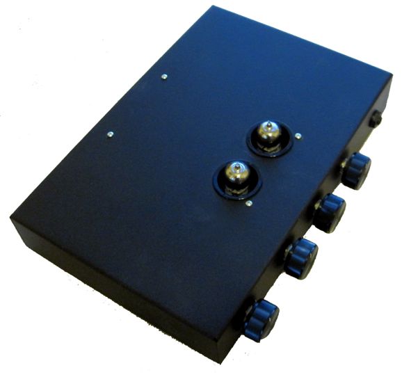
Finished Project: Hybrid HPA
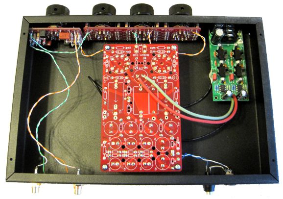
In that same post, I mentioned that it would mate well with a harmonic restoration circuit. Well, since I had a built up 12Vac SRPP just sitting in a box filled with assembled PCBs, I decided to go for it. The chassis I had on hand was 12 inches wide and 8 inches deep and 2 inches tall. The drilling and punching was a breeze, in spite of the hard steel enclosure. The secret is wide masking tape. Just run a strip along the front and back, and then marked off where the holes need to be drilled. The ruler doesn't slide off the tape as easily as it would on the painted chassis. In addition, the tape protects the front and back from the drill bit.
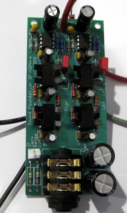
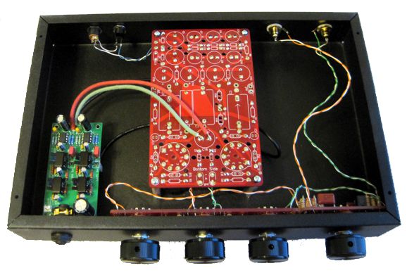
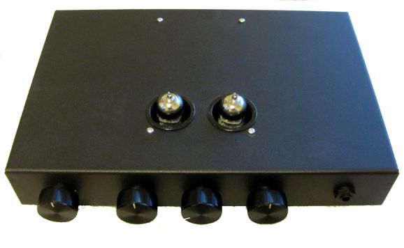
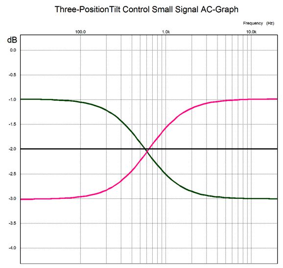
I altered the SRPP PCB to accept the 6DJ8, rather than the 12AU7. Then I built up a three-position Tilt Control and an A3 Mini stepped attenuator. The power jack at the back accepts the 12Vac power-supply voltage from a 2A wallwart. Next to it, the power switch resides.
I cannot imagine listening to headphones without the Tilt Control, as I find that I use it all the time, switching with genre and album.
The Tilt Control version I used is the three-position one designed to work with a 50k volume control, which the A3 Mini presented.
I configured the A3 Mini stepped attenuator to present a 50k input impedance, and -1dB and -6dB fine and coarse steps. The outer knobs effectively function as a balance control, which comes in super handy when listening to headphones, for unlike loudspeakers where you can move closer to the weak channel, your position relative to the headphones is fixed. The chassis is mostly empty, as the power transformer is outside it. This arrangement also makes for less heat and hum.
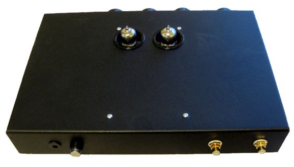
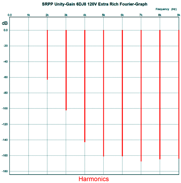
Fairly cute, this headphone amplifier, don't you think? If I were given to bestowing names on my audio gear, this project would be named the "Black Beauty." How does it sound? Not nearly as ripe as I expected. In fact, the resulting sound was barely ripe. What went wrong, or rather went right? When designing the SRPP harmonic restoration circuit, I ran my SPICE simulations with an input signal of 1Vpk. But that is not what goes on in headphone listening, as 1Vpk would blow my eardrums out after being amplified by the solid-state amplifiers. Here are the results with an input signal of only 0.1Vpk.
Not so extra rich. Bear in mind that -60dB equals 0.1% distortion. Okay, time to fine tune.
Bi-Amped Amplifiers?
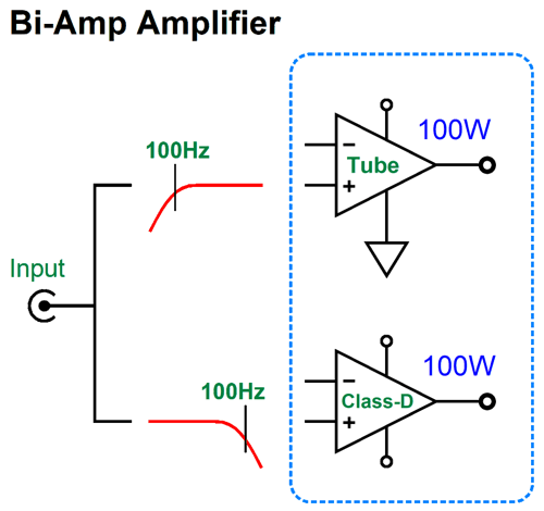
Okay, returning to audio power amplifiers, powerful tube-based power amplifiers not only require many large output tubes, but a huge output transformer. If we gave the output transformer some thought, we would realize that the output transformer should be much larger than the power transformer, as it must pass far lower frequencies. The usually stated lower limit human hearing is 20Hz. Some have claimed, however, that for a power amplifier to reproduce deep bass adequately, its low-frequency bandwidth must extend down to below 2Hz, a full decade lower than 20Hz. If a solid-state amplifier is DC coupled throughout, from input to output, 2Hz is not a big deal, as it can pass and amplify DC. Here's the problem with making a 100W tube-based power amplifier with bandwidth down to 2Hz: the output transformer would have be about as big as refrigerator, possibly bigger still. Think about it: transformers cannot pass DC voltages, much in the same way that coupling capacitors cannot pass DC currents; and low-frequencies, such as 2Hz, approach DC, as the wide wavelengths begin to resemble runs of DC voltage. With a tube-based, transformer-coupled amplifier, the higher the low-frequency cutoff frequency is, the smaller the output transformer can be. For example, if we limited the low-end bandwidth to only 100Hz, the output transformer could be far smaller, looking more like a 20W transformer, yet put out 100W. This got me thinking that modern tube-based amplifiers could easily come with a built-in class-D power amplifier; let's say 100W of tube-based output above 100Hz and 100W of solid-state class-D output below 100Hz. In fact, the addition of the 100W class-D amplifier would probably prove less expensive that a single high-end coupling capacitor. The enclosure is the most expensive part of a class-D amplifier.
Such a set up would make adding a passive subwoofer a breeze, the active crossover would be internal to the amplifier. Indeed, such an amplifier might work well with a bi-wired loudspeaker, if eliminate the low-pass filter in the class-D amplifier, as the speaker's own two separate internal passive crossovers will need to see close to full bandwidth amplifier signals. (I assume that 1st-order 100Hz high-pass filter on the tube-based amplifier will not cause problems with two-way speaker whose tweeter crosses over above 2kHz.) Okay, now we move on to the radical idea and much Gedanken-experimenting. What if the two amplifiers, the tube-based and the solid-state, could join to create a single output signal? In other words, what if we created an internally bi-amped amplifier, with one output, not two? Such an amplifier could drive a fullrange loudspeaker that held a single driver. The tube-based amplifier would deliver frequencies above 100Hz, while the class-D amplifier, those below 100Hz. My mind reels. Is this possible? Maybe. Let's start with two fullrange solid-state power amplifiers, so we can avoid the output transformer issue. How can two power amplifiers sum into a single output? A direct connection of outputs will lead to smoke and frustration. Two 4-ohm series resistors would work, but would prove hugely inefficient and present too high an output impedance. What is needed is reactive devices, such as capacitors and inductors.
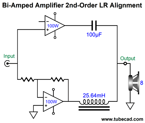
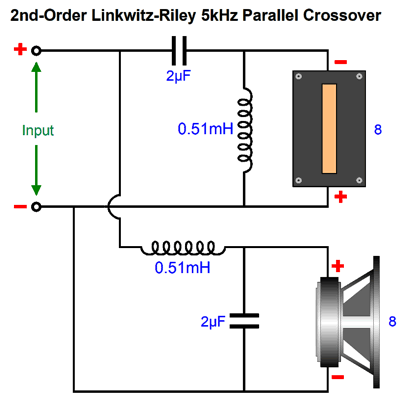
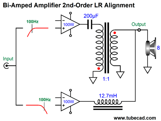
To the eye this looks like a 1st-order crossover. It isn't, as it forms a 2nd-order crossover. From the 100µF coupling capacitor's perspective, the inductor is terminated into ground; from the inductor's, the capacitor is terminated into ground.
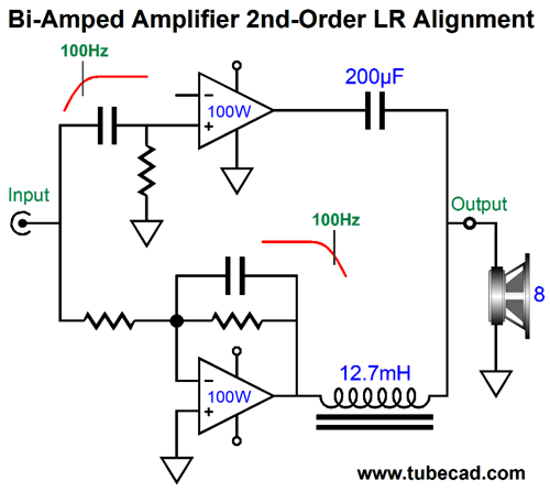
Now, 2nd-order LC crossovers can be set to several different alignments, such as Bessel, Butterworth, Gaussian, Linkwitz-Riley, Thompson… Since our goal is a flat frequency response, we must choose the Linkwitz-Riley, whose Q is 0.5 and whose output is -6dB down at the crossover frequency, so the sum is unity. The amplifier schematic shows the Linkwitz-Riley required values, which halve the capacitor value and double the inductor value, just as we do with loudspeaker drivers. Because this is a 2nd-order crossover, the phase must be flipped on one of the amplifiers, much in the same way that the phase must be flipped on one of the loudspeaker drivers with a Linkwitz-Riley passive crossover, as 90-degree phase shift results at the crossover frequency for the tweeter and -90-degree shift for the woofer, making for a total of 180 degrees and a deep null without the phase flip. Note that both power amplifiers must run fullrange, which seems rather pointless, as we do not gain any frequency-dependent advantage. The workaround is to impose filters in front of the amplifiers, whose crossover frequency equals that set by the coupling capacitor and inductor; in this example, 100Hz.
Note that the output coupling capacitor and the inductor no longer adhere to the Linkwitz-Riley alignment, but the Butterworth, with a Q of 0.7. Why? The two 1st-order crossover filters in front of the power amplifiers impose -3dB down outputs from each amplifier, so the coupling capacitor and inductor must also impose a -3dB down output, so the total at each amplifier's output comes to -6dB. The result is a flat frequency response, with an 8-ohm load, however, not with a 4-ohm or 16-ohm load. With a 4-ohm speaker, a -6dB dip occurs at 100Hz; with a 16-ohm speaker, a +6dB bump at 100Hz.
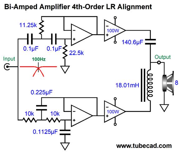
Here we have run into a mental speed bump in our thought experiment. Virtually no loudspeaker is a flat 8-ohm load. (This is an interesting example of an amplifier that would pass all the electrical tests with an 8-ohm dummy load and fail in reality with an actual loudspeaker.) Each amplifier gets a limited slice of the full audio spectrum of frequencies, but not an equal slice, as the high-frequency amplifier has much more to contend with than the low-frequency amplifier. Like arbitrary but useful Caesar with Gaul, I divided the audio bandwidth at 100Hz. The actual geometric split of the bandwidth of 20Hz to 20hKz is 632Hz. Imagine that the input signal is a 10kHz sinewave. The bottom amplifier will only be putting out 1/100th of the output of the high-frequency amplifier. Strictly speaking, we do not need to flip the low-frequency amplifier's phase to achieve a flat frequency response, but the output is not anything close to phase flat, as the loudspeaker will see a shift of 360 degree shift from 10Hz to 10kHz. Each amplifier sees a 90-degree phase shift relative to each other. So, we have to choose between having the low-frequency amplifier's output lag by 45 degrees at the crossover frequency or lead by 135 degrees, which relative to the high-frequency amplifier's 45-degree leading, as both give the same 90-degree difference. If we examine tone-bursts at the crossover frequency, we see that inverting the low-frequency amplifier output might make for better bursts of sinewaves. Okay, how much further can I take this thought experiment? Well, what if we place a 2nd-order filter in front of each amplifier?
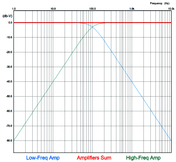
Note that neither amplifier's phase is inverted. We don't need to, as the two 2nd-order filters introduce the needed phase inversion. The filters hold to a Butterworth alignment with a Q of 0.7, so each amplifier's output will be down -3dB at the crossover frequency. This forces us to alter the output coupling capacitor and inductor alignment to also a Butterworth alignment, so the final reduction from both amplifiers is -6dB at the output, which sums to unity, as 0.5 + 0.5 equals 1. Both amplifiers see -40dB per decade slopes from the crossover frequency. In other words, very little overlap, as the following SPICE-generated graph shows.
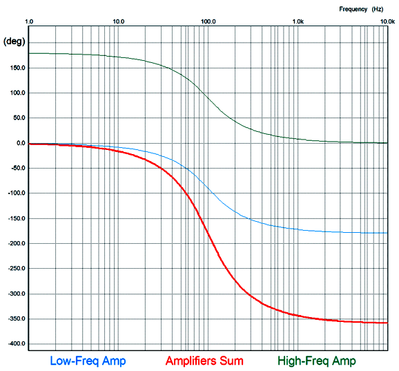
Next, we see the phase response.
At 100Hz, the phase is -180 degrees. We could flip the phase on the speaker wires, which would put us back to zero at 100Hz. Let's look at a tone-burst of two cycles at 8Vpk at 100Hz.
Note that the two cycles become three cycles that extend beyond the input signal's end. This what 4th-order crossovers do and why I prefer 1st-order and other phase-flat crossovers. Okay, let's now introduce an output transformer.
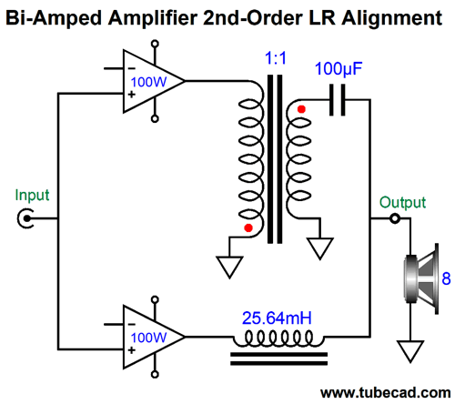
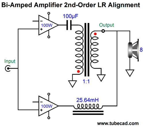
The assumption here is that the transformer offers full bandwidth. Note that the required phase inversion of one amplifier's output is accomplished through flipping the connection to the transformer's primary. The high-frequency amplifier could be either a tube-based OTL or a solid-state DC-coupled power amplifier. We can even move the coupling capacitor to the primary side of the transformer.
The assumption here is that the output transformer offers a winding ratio of 1:1, so both amplifiers work into an 8-ohm load. If we used an output transformer with a winding ratio of 3.16:1, which implies an impedance ratio of 10:1, we could get away with a 10µF coupling capacitor, but the high-frequency amplifier would have to be able to swing 126.5Vpk of output to make 100W of output power. Of course, it would be working into an 80-ohm load, not an 8-ohm load, so the peak current swing would be only 1.58A, not 5A. Getting 5A of peak current flow from tubes is not easy, but getting only 1.58A is 3.16 times easier. Both amplifiers see a full bandwidth input signal. We can add 1st-order filters to the amplifier inputs.
Interestingly enough, these 1st-order filters are freebies of sorts. How so? They do no produce any additional phase shift. as a 1st-order crossover sums to unity and is phase flat. In other words, although the two amplifiers see a truncated bandwidth, the signal arriving at the loudspeaker is identical to that produced by the previous circuit without the filters. SPICE simulations bore this out.
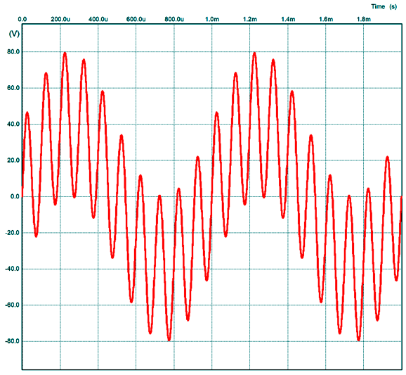
Note that the phase shift is +90 degrees at the crossover frequency of 100Hz, which implies a 2nd-order crossover. Here is the SPICE-generated transient graph of a 100Hz input signal.
Note that input signal crosses zero at 10ms and 20ms and 30ms and that the summed output leads by 90 degrees. Here is the graph for a 1kHz input signal.
The phase is greatly reduced. Note that the low-frequency amplifier's output is substantially reduced and phase shifted relative to the high-frequency amplifier. As you can see, adding an output transformer didn't radically change the situation compared to the previous designs without the transformer. . What would make a radical change is to have the low-frequency amplifier drive the other end of the secondary.
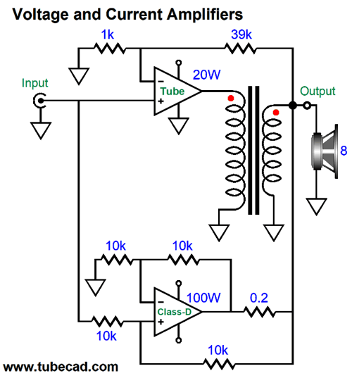
The idea behind this arrangement is that the class-D amplifier drives the tube-based amplifier's output transformer's secondary, so that the class-D amplifier's output and the tube-based amplifier's output would sum. At exactly 100Hz and with 100W of output power into an 8-ohm load, both amplifiers deliver 28.28Vpk, but the speaker does not see 56.56Vpk, but only 40Vpk. The two amplifier output differ in phase at 100Hz by 90 degrees, so we must take the sin(45) against 28.28Vpk to get the resulting sum of 40Vpk, which across an 8-ohm load equals 100W. By the way, no 100W amplifier can put out 100W at 10Hz and 100W at 1kHz at the same time. Why not? The 100W amplifier's voltage swing limit is 40Vpk (or 80Vpk-to-pk). Two 40Vpk swings would sum to peak voltage swings of 80Vpk, something a 400w amplifier can put out, but not a 100W amplifier, which is limited to 40Vpk. Therefore, the maximum output for these two frequencies at the same time would be 20Vpk, which would equal 25W at each frequency. This explains why two 25W amplifiers in a bi-amped setup can sound as powerful as a 100W amplifier. In contrast, in this two-amplifier amplifier, both amplifiers could put out 100W at the same time, so we could get 10Hz and 1kHz at 40Vpk each.
One absolutely essential feature is that the tube-based amplifier's negative feedback loop cannot extend to the secondary, only to the plates or to a tertiary winding. If the feedback loop did encompass the secondary, the solid-state amplifier's output would be treated as distortion, so the tube amplifier would strive to impose the high-pass filtering. One workaround might be to remove the 100Hz high-pass filter for the tube-based amplifier, so it sees a fullrange input signal and its negative-feedback loop would then welcome the solid-state amplifier's contribution. The solid-state amplifier would still see its 100Hz low-pass input filter, while the tube-based amplifier's output would intrinsically—due to its negative-feedback loop—follow 100Hz high-pass filtering. Moreover, the tube amplifier's negative feedback would work to undo any distortion arising from the solid-state amplifier. In fact, this setup would effectively create a phase-flat asymmetrical crossover.
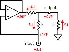
The example circuit is from post 474. In the circuit below, the output transformer mimics the four-resistor differential amplifier shown above.
Could this work? It might, but it scares the hell out of me. Why? The output transformer. Output transformers are a gooey mess, with complicating elements, such as wire DCR and leakage inductance and stray capacitances—all of which screw with the phase relationships. Still, with patience and persistence, it could work. Here is what SPICE showed with a full-bandwidth output transformer.
What happens when just a 10kHz input signal is encountered? The solid-state amplifier's output will be -80dB down, which means that at 100W of output, it will contribute just 40mVpk, while the tube-based amplifier makes up the difference needed to get to 40Vpk. At high frequencies, we can treat the class-D amplifier as being just virtual ground; at low frequencies, the tube-based amplifier as a virtual ground. In other words, both amplifiers always undergo the same current swings in phase, although their output voltages and phase will differ.
This situation is not like an impedance-multiplier circuit (IMC) shown above, wherein currents add together. Instead, in all the bi-amped amplifiers that use an output transformer, the currents do not add together. In other words, if the speaker sees 1A of current flow, both amplifiers also see 1A of current flow. This brings up a concern: won't the solid-state amplifier muddy up the tube-based amplifier output, as the two outputs are effectively in series? It might. One workaround might be to switch from the 1st-order crossover to a 2nd-order set of filters. How could that possibly help? The workaround uses one low-pass filter after the class-D amplifier's output and one before.
Note how the RC filter shunts the bottom of the secondary to ground at high-frequencies; at low frequencies, the solid-state amplifier can power through the resistor and capacitance. The 1-ohm RC resistor will get plenty hot, so a 25W resistor should be used. Effectively, the solid-state amplifier is driving a 4-ohm load at 20Hz and a 1.78-ohm at 100Hz. Won't this cause the amplifier to blow up? Not if the amplifier is a class-D amplifier designed to drive car subwoofers, which can be as low as 2-ohms. In other words, in this arrangement, the class-D amplifier would need to be rated for much more than 100W, but that is not that big a deal with class-D. If we wanted to truly bi-amp, with a passive subwoofer, then the RC filter must be removed and a second 1st-order 100Hz low-pass filter must feed the class-D amplifier. Both amplifiers see 2nd-order Linkwitz-Riley crossover slopes of 12dB per octave and 40dB of attenuation per decade. Most importantly, both outputs will be down -6dB at 100Hz and 180-degrees out of phase, so the transformer's primary must be flipped, so the two outputs can be in phase. The result is a frequency-flat summing, but also a non-flat phase response. It that important? It might be, but since it occurs at 100Hz, it might not make any real difference. Remember that All loudspeakers that use 2nd-order crossovers also undergo the same phase deviations. We could just easily forgo the RC filter and place the entire 2nd-order low-pass filter (made up from two 1st-order filters in cascade) ahead of the tube and class-D amplifiers.
Were back to the class-D amplifier being entirely in series with the tube-based amplifier's secondary. Well, this thought experiment must come to an end—for now. It's quite possible that some of the problems I encountered along the way would disappear with current-out amplifiers, rather than with the voltage-out amplifiers I assumed. Or, perhaps, some blend of voltage-out amplifier and current-out amplifier would work best.
The class-D amplifier is configured as a Howland current pump, which converts 1Vpk of input signal into 5Apk of output current, which implies a peak output voltage of 40V into an 8-ohm load. The 20W tube-based voltage-out amplifier's gain is set to 1:40, so in theory it shouldn't deliver any current into the speaker. In reality, the speaker's deviation from 8-ohms will force current output from the tube amplifier. For example, if the speaker is a 4-ohm type, then both amplifiers must deliver 5A of peak current, as 40V divided by 4 ohms equals 10Apk. If the load is 16 0hms, the tube amplifier must sink 2.5A, as 40V/16 equals only 2.5A. In short, only some planar speakers that present flat impedances would work. (If we switch to headphones, especially planar headphones, such as the HE400i, the ruler-flat impedance would work perfectly with this arrangement. Imagine a single-ended OTL tube headphone amplifier and an OpAmp-based howland current pump.) See post 238 for more information on current-out amplifiers and the Howland circuit.
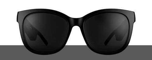
Bose Frames Audio Sunglasses What interested me most about them is that I have long wondered how to improve headphone listening. For over 40 years now, I have used a subwoofer with my headphones, as the big woofers impart a somatosensorial (i.e. pertaining to or characterized by sensory activity having its origin elsewhere than in the special sense organs—such as eyes and ears—and conveying information about the state of the body proper and its immediate environment) wallop otherwise lacking with headphone listening. I have even thought about introducing a time delay to the digital data-stream feeding the headphone amplifier's DAC, so the subwoofer's output would precede that of the headphones, allowing the deep bass to come into time alignment with the headphone output. (Off topic, but when will Klipsch come out with a bi-amped Korner Horn that is time aligned, as the woofer's output lags far behind the midrange and tweeter output by about 10ms or so? This is something I have longed to hear for half a century now. This setup would require a digital input signal, so the time delay could be imposed on the data-stream that the high-frequency DAC sees. As a teenager, I thought that an open-real tape player with two playback heads, one located in front of the other, could be used to provide the high frequency delayed signal. A time aligned Klipsch corner horn powered by two tube amplifiers could be audio nirvana.) Three years ago in post 451, I presented a new audio-equipment category: HeadWoofer™, which was a subwoofer designed to work with headphones.
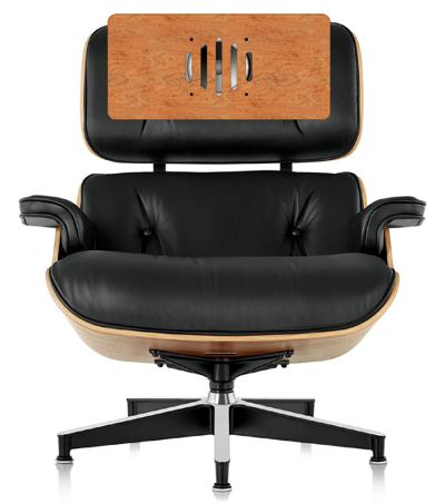
I have even thought of adding butt-shaker drivers (bass shaker tactile transducers) to a listening chair for headphone use. You know, those cone-less, puck-like drivers that are used in home-theater setups attached under a sofa or chair to deliver sonic thumps during space battles and car crashes in movies.
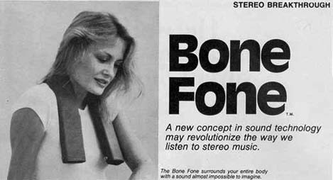
Well, the new Bose sunglasses and the old Bone Fone both use indirect means to let us hear the music. What if we used something like a super Bone Fone for just frequencies below 100Hz with our high-end headphones? In other words, what if we wore amplified butt-shaker drivers over our collar bones? We all hate wires, so Bluetooth would be a must, along with rechargeable batteries.
I called it in March!
It takes some time for the thunder to catch up with the Lightning. https://www.sciencedaily.com/releases/2020/09/200930094758.htm https://phys.org/news/2020-12-covid-neandertals.html
Music Recommendation: Grace Audiophiles will delight in the first song, Barley, which will give your subwoofers a good workout. Unfortunately, her voice is not that well recorded throughout the album, sounding oddly flat and distant, contrasting with the instruments which are vividly portrayed. Unlike Norah Jones or Diane Krall, she does not get the royal treatment. I would love to know what was going on in the recording engineer's mind. In fact, much of the album's sonic presentation sounds gimmicky and strained; in addition, the back-up singers are poorly recorded as well. I understand that massed voices are particularily dificult to capture, but other albums manage it. Surely, her voice should be presented best, then the instruments. Apparently the recording engineer thought the opposite. Maybe, this album was mixed to sound best on a smart phone or in a car. Too bad, as she deserves much more. //JRB
User Guides for GlassWare Software
For those of you who still have old computers running Windows XP (32-bit) or any other Windows 32-bit OS, I have setup the download availability of my old old standards: Tube CAD, SE Amp CAD, and Audio Gadgets. The downloads are at the GlassWare-Yahoo store and the price is only $9.95 for each program. http://glass-ware.stores.yahoo.net/adsoffromgla.html So many have asked that I had to do it. WARNING: THESE THREE PROGRAMS WILL NOT RUN UNDER VISTA 64-Bit or WINDOWS 7, 8, and 10 if the OS is not 32-bit or if the OS is 64-bit. I do plan on remaking all of these programs into 64-bit versions, but it will be a huge ordeal, as programming requires vast chunks of noise-free time, something very rare with children running about. Ideally, I would love to come out with versions that run on iPads and Android-OS tablets.
|
I know that some readers wish to avoid Patreon, so here is a PayPal donate button instead. Thanks. John Broskie
John Gives
Special Thanks to the Special 90
I am truly stunned and appreciative of their support. In addition I want to thank the following patrons:
All of your support makes a big difference. I would love to arrive at the point where creating my posts was my top priority of the day, not something that I have to steal time from other obligations to do. The more support I get, the higher up these posts move up in deserving attention.
If you have been reading my posts, you know that my lifetime goal is reaching post number one thousand. I have 476 more to go. My second goal is to gather 100 patrons. I have 20 patrons to go. Help me get there.
Only $9.95
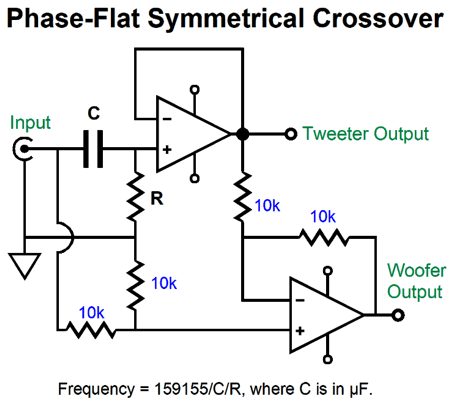
The Tube CAD Journal's first companion program, TCJ Filter Design lets you design a filter or crossover (passive, OpAmp or tube) without having to check out thick textbooks from the library and without having to breakout the scientific calculator. This program's goal is to provide a quick and easy display not only of the frequency response, but also of the resistor and capacitor values for a passive and active filters and crossovers. TCJ Filter Design is easy to use, but not lightweight, holding over 60 different filter topologies and up to four filter alignments: While the program's main concern is active filters, solid-state and tube, it also does passive filters. In fact, it can be used to calculate passive crossovers for use with speakers by entering 8 ohms as the terminating resistance. Click on the image below to see the full screen capture.
Tube crossovers are a major part of this program; both buffered and un-buffered tube based filters along with mono-polar and bipolar power supply topologies are covered. Available on a CD-ROM and a downloadable version (4 Megabytes). Download or CD ROM
|
|||


| www.tubecad.com Copyright © 1999-2020 GlassWare All Rights Reserved |