| John Broskie's Guide to Tube Circuit Analysis & Design |
|
Post 224 18 January 2012
It is time for me to fix a small problem. In blog 221, I described a push-pull, low-noise variation on the classic Aikido topology —but I failed to give it a name. Why not? I readily admit that I adore, delight in, get a kick from and out of, get off on, love, take pleasure in exploring, understanding, and creating circuit topologies. Indeed many believe, rightly so no doubt, that I am like a politician insane from power and that I have become a tad too lubricated, plastered, ripped, smashed, soused, too stinko from drinking so deeply from the fountain of topology. Okay, everyone already knew that. But what I don't like about electronic topologies is the act of naming them. In fact, I positively oppose and boldly retreat from pasting labels upon circuits. Why? I never see any electronic circuit as ever being truly finished, completed, fixed, and finished. Adaptation, alteration, change, metamorphosis, modification, mutation, permutation, transfiguration, transformation, translation, transmogrification —hell, let's add transmutation to the list—all are always possible. Sticking a name on a circuit, in contrast, seems to fix it in place, to freeze its development, and to embalm it. In other words, naming an electronic circuit is like adding a monument to or a tombstone over a dead topology. Yet, without a name, the circuit has no currency, no general acceptance, as the nameless remains, at least partially, unknown. To be inexpressible is close to not existing.* So, name I must. But how should I name? My inclination, much like Sigmund Freud's, is to pilfer from ancient mythologies; my inclination is well established by my Janus and Sagaris appellations.
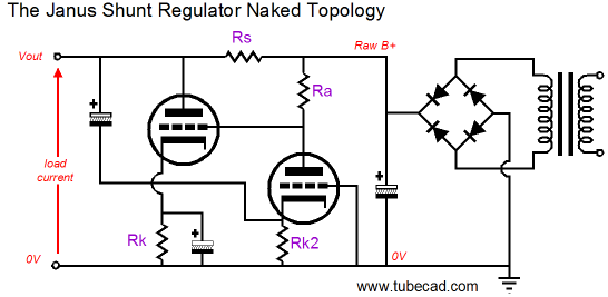
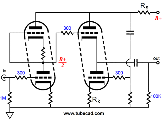
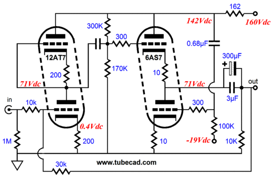
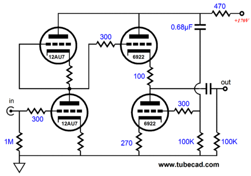
The Janus shunt regulator looks both ways, forward to the load being powered and backward to the rectifier's output, much as January—also named after the god of gates and doors and beginnings and endings—looks back into last year and forward to this year. The name "Aikido," on the other hand, is a fairly recently coined word, which I use to label the technique of eliminating power-supply noise from the output by anticipating its presence and countering it simultaneously. Where the traditional method of applying as much negative feedback as possible after the fact is the brute force reactive technique, the Aikido method is subtle, clever, and proactive, much like the martial art. Thus, while the name "Aikido" may be a bit whimsical, it is also apt. Since I already have indulged whimsy with the Janus and Aikido names and since this new circuit is a variation on the Aikido topology, the best name is probably the accurate, but somewhat stodgy Aikido Push-Pull. Indeed, the original Aikido topology can be accurately labeled the Aikido Single-Ended. From now on, I will refer to the topology shown below as the "Aikido Push-Pull." By the way, push-pull here refers to the output stage, not the input stage, which is still a purely single-ended affair. (It drives me crazy when I see the original Aikido being described as two SRPP stages in cascade, for nothing pushes and pulls.)
In the Aikido Push-Pull topology, the two key resistors are Rk and Rs. If their values conform to a set of relationships defined by a few formulas, the circuit exhibits four wonderful attributes:
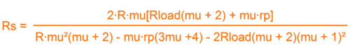
If these resistors are not carefully chosen, then much of the magic disappears. I do not like to repeat myself, but the following two-step design procedure is worth repeating. The first step is to find the cathode resistor's value for the output stage, which will ensure the deepest null in power-supply noise at the output: Rk = rp(mu -2) / (mu² + 3mu + 2) The second step is to find the resistance R, which is the effective resistance of one of the input stage's triodes and its unbypassed cathode resistor, not the output stage cathode resistor: R = rp + (mu + 1)Rk The third step is to plug R into Chris Paul's formula:
Before moving on, stop and ask yourself if you really need a high-output-current tube amplifier stage. You do? Really? Why? Are you driving headphones or some other low impedance load? Sorry, but a 47k input impedance from a power amplifier does not count. If you plug 47k into the above formulas, you are likely to get a negative value for Rs, which sad to say cannot be bought.
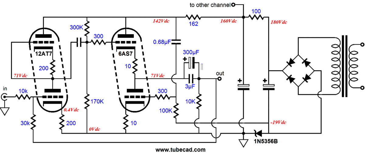
6AS7 Special Case
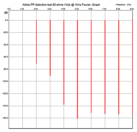
The design is actually over four years old, but I slightly modified it's part's values so that it would be optimized to work with a 50-ohm load, such as presented by the new planer-electromagnetic headphones. (The idea was that an iPod would be the signal source, so no volume control would be needed and the negative feedback loop would set a gain of about 2.) I have sent it out to several readers (and one Asian tube amplifier company), but I don't know how many have built it. The need for a negative power supply rail will daunt many tube-loving DIYers. (Click here for a schematic that shows how a faux negative power supply can be created with a single, non-tapped secondary winding.) The idle current for the 6AS7 is a high 100mA, which means that the amplifier can put out a current peak of 200mA, which implies a peak voltage swing 10Vpk into 50 ohms. In SPICE simulations, the circuit performs insanely well, delivering low distortion, low Zo, and fantastically low power-supply noise. Moreover, its harmonic structure is still very single-ended looking, as you can see below.
Note how no two-resistor voltage divider was used to feed the Aikido cathode follower's bottom triode its input signal. This conforms to the standard Aikido formula: Rtop = Rbottom x (mu – 2) / (mu + 2) But in this case, with the mu equal to 2, the top resistor's value falls to zero. With just about any other triode, such as the 6H30 or 12B4, the top voltage-divider resistor is still absent, as we want 100% of the power-supply noise to be presented to the bottom triode's grid. And the more complex formula will be needed to find the bottom triode's cathode resistor value. Rk = rp(mu -2) / (mu² + 3mu + 2)
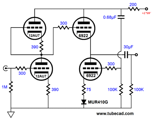
Too Hot Aikido PP
This workaround is easy enough, when we want to decrease the idle current: we just place some rectifiers in series with the cathode resistor. I always use MUR410G rectifiers, because of their consistent voltage drop—about 0.52V—and low ESR. In the above schematic, the rectifier's inclusion drops the 6922's idle current from 13.2mA to 10mA; two rectifiers in series drops the current down to 7.3mA. The SPICE model for the MUR420G (I don't have the model for the MUR410G) states that its ohmic resistance is a mere 0.02348.
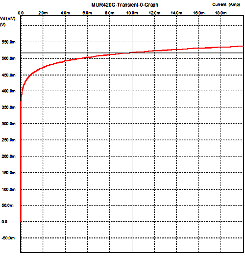
But with 10mA of idle current, as can be gleaned from inspecting the graph below, it's actually about 3.5 ohms.
Or, we can add a cathode resistor to the top triode's cathode, which effectively creates an effective triode with an rp equal to rp + (µ + 1)Rk, Rk refers to the top triode's cathode resistor, not the bottom triode's resistor. We plug this new rp into the formula for finding the bottom cathode resistor and then add the top Rk's value to the bottom Rk's value. Then we use Chris Paul's formula to find the value of the series-sense resistor, using the effective rp value.
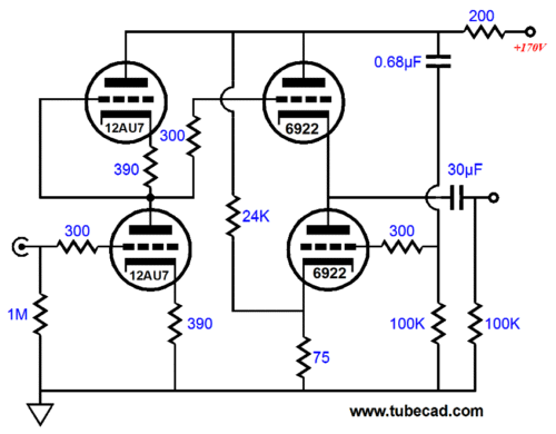
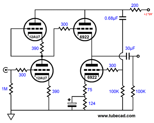
There are at least two other ways to use the Aikido PP with a reduced idle current: attach a large-valued resistor from the top triode's plate to the bottom triode's cathode or place another cathode resistor in series with the bottom triode's cathode resistor, but bypass the new resistor with a large-valued capacitor.
The added 24k resistor allows more current to flow through the 75-ohm cathode resistor, which will increase the voltage drop across the cathode resistor, which will, in turn, decrease the current flow through the output triodes. The downside is that the distortion goes up slightly.
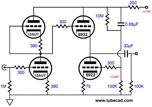
This is the most obvious workaround, which might be why I dislike it so. Nonetheless, the added bypassed cathode resistor allows us to easily set the desired idle current. Okay, what if after running the formulas, we end up with a cathode resistor whose value is too great, as it excessively decreases the idle current? The easiest workaround is to place a hugely-high-valued resistor in parallel with the 0.68µF coupling capacitor, as this will inject a positive DC voltage into the bottom triode's grid. The problem with this workaround is that it is difficult to find resistors greater than 22M; of course, several could be placed in series.
Next Time
* What happens when we don't have a name? Is it possible to be unnamed, as the word "nameless" is there to cover it? William Gladstone (1809 – 1898), the four time British Prime Minister, pointed out that the Ancient Greeks had no word for the color blue. But didn't the sky and sea look the same blue to them as it does you and me today? The greeks, by the way, did have words that we don't have an equivalent word for, such as "thumos," which might be described as girly, womanly courage. Then there the problem of a name being given too much scope; for example, for many tube lovers any time two tubes are in a totem-pole position, with one triode atop another, such as in the cascode or the White cathode follower or in the Aikido cathode follower, the name "SRPP" is applied.
//JRB |
|
I know that some readers wish to avoid Patreon, so here is a PayPal button instead. Thanks.
John Broskie
E-mail from GlassWare customers:
And
High-quality, double-sided, extra thick, 2-oz traces, plated-through holes, dual sets of resistor pads and pads for two coupling capacitors. Stereo and mono, octal and 9-pin printed circuit boards available.  Aikido PCBs for as little as $20.40 http://glass-ware.stores.yahoo.net/ Only $12.95 TCJ My-Stock DB
Version 2 Improvements *User definable Download or CD ROM www.glass-ware.com |
||


| www.tubecad.com Copyright © 1999-2012 GlassWare All Rights Reserved |