| John Broskie's Guide to Tube Circuit Analysis & Design |
28 February 2016 Post 373
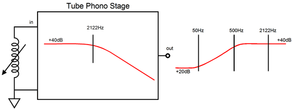
Phono Stages for Digital Ripping In other words, the phono stage designed for ripping LPs might need only provide 40dB of total gain (assuming a high-output phono cartridge), compared to the same phono stage that would have to provide 60dB of total gain, as the bass frequencies for normal LP playback require 20dB boost over the middle frequencies.
Using a single OpAmp could achieve this goal. (I know that you assumed a solid-state OpAmp would be used, forgetting that tube-based OpAmps are possible and that—in fact—have been made and sold.)
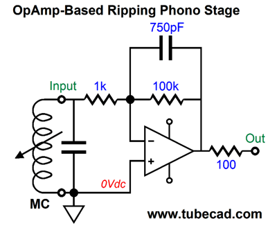
The assumption here is that a high-output moving-coil cartridge would be used. This might prove a bad assumption, as most high-output moving-coil cartridges are designed to be loaded by 100pF and 47k, just like moving-magnet cartridges. (My own Dynavector 10X5 cartridge works best with load impedance greater than 1k, say 10k.) Alternatively, we could use one OpAmp and use passive filtering
The above circuit uses passive equalization to achieve the 2122Hz low-pass filter function. Its gain is a tad over +40dB. This might be the easiest and best solution. But then, it might not be, as the OpAmp must flatly pass the ticks and pops and the 100-ohm load impedance due to the low-pass filter's 100-ohm resistor is a tough load for many OpAmps. In addition, the ADC own input impedance will throw off the 2122Hz transition frequency. Note the Catch-22 here: if we make the RC resistor larger in value to unburden the OpAmp, we make the low-pass filter more susceptible to loading problems; if we make the RC resistor smaller in value to make the low-pass filter more immune to loading problems, we burden the OpAmp with too low a load impedance.
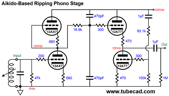
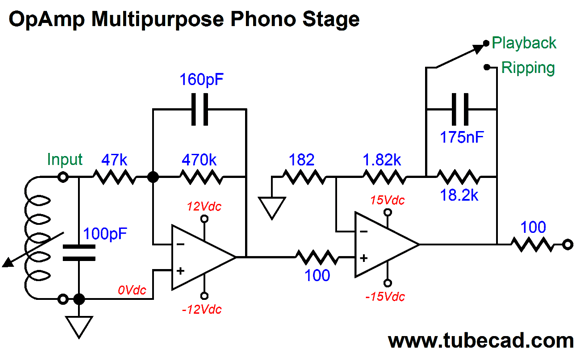
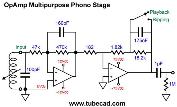
The above tube version would solve all these potential problems. This circuit imposes the 75µS time constant and offers good PSRR and a low output impedance. The only potential problem that I can foresee is it may fall short of is gain, as it would only put about +33dB of gain. By the way, by placing a step-up transformer at the input, we could use a low-output MC cartridge. Note the two 470pF capacitors. Why two capacitors? The ACF output stage expects to see 50% of the power-supply noise at is input, so only using one capacitor to ground would deliver this ratio only at low frequencies, not high frequencies. By using two capacitors, we still achieve the low-pass filter function and we still present 50% of the power-supply noise at all frequencies to the ACF's input. But let's return to OpAmps, the solid-state kind. Why? The OpAmp is actually not an IC or a bunch of discrete parts, rather it is meta electronic concept, a bundling of many desirable attributes, such as infinite input impedance and bandwidth, with zero output impedance and noise—and, most importantly, perfect differential amplification. One day, actual physical OpAmps might be made by out of devices that do not exist today, say quantum cells, but as long as it conforms to meta electronic concept of "OpAmp," we will think of it as an OpAmp. I like to start by envisaging an electronic system filled with OpAmps, then I end by replacing the OpAmps with tube circuitry. The following design offers two modes of operation: partial RIAA EQ for LP ripping and full RIAA EQ for LP playback.
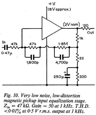
The input OpAmp provides a gain of 10 (+20dB) and imposes the 2122Hz low-pass filter. The second OpAmp, as shown, is configured as a playback phono stage with a final gain of +40dB at the middle and high frequencies, but +60db of gain at frequencies below 50Hz. With the switch flipped to the "ripping" position, however, the second stage offers only a gain of +20dB and a flat frequency response. No doubt, many are troubled by the inverting configuration of the left OpAmp. It just seems so wrong in a phono preamp. John Linsley Hood, in 1971,= in the September issue of Wireless World magazine, revealed the following phono circuit, which used discrete transistors.
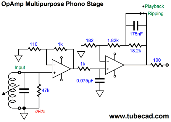
At the time, this design struck me as crazy, which troubled me greatly, as I viewed JLH as my hero (I still do, by the way). He then, if my memory serves me correctly, published an OpAmp-based version in HiFi News magazine in the late 1970s. I decided to test his novel idea by building two phono stages: one with his inverting configuration and one with non-inverting layout, which were otherwise identical, as both used passive equalization between two gain stages. I used a remote power supply, so I could easily switch between phono stages. The JLH approach was ever so slightly more noisy, but imaged much better, so much so that was the topology that I choose to live with, in spite of the slight increase in hiss. (I had used 1% metal-film resistors from Corning. I then found at an electronics surplus store some huge, non-inductive, 47k wire-wound resistors. Dang, they sounded much better and quieter as the input resistor.) For those that simply cannot abide the idea of an inverting input stage, the following design does not invert.
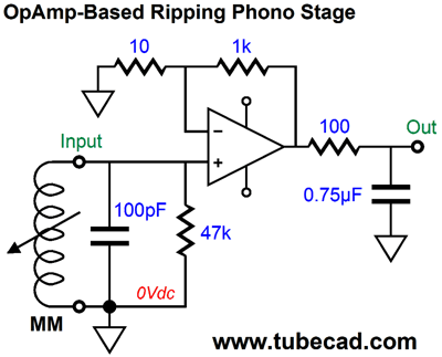
The first OpAmp provides a gain of +20dB, while the second OpAmp, with the switched closed as shown in the schematic, offers a gain of about +20dB, which brings us to our goal of +40dB for ripping LPs. The 1k resistor and 0.075µF capacitor form a low-pass filter with a -3dB down frequency of 2122Hz. With the switch opened, the phono stage completes the RIAA equalization and is ready for LP playback. Of course, we could cascade two inverting stage, as show below.
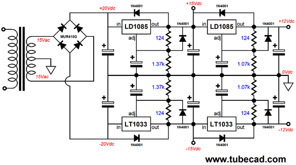
Note that the input OpAmp must drive a 182-ohm load impedance. Fortunately, it does not have to deliver either much voltage or current into this load. The coupling capacitor was added as safety feature, when using the phono stage for regular LP playback. Also note the +/-15V and +/-12V power-supply-rail voltages. The idea is to use cascading linear regulators so that the 12V and 15V rails are available, with the 12V rails being extra clean.
A super-long-time reader, Randy, wrote me, asking if this trip was really necessary. He pointed out that many were using flat phono stage that implemented no RIAA equalization for ripping LPs, as all the reverse RIAA EQ compensation would be performed in the digital domain. He provided me with the following link: http://www.tracertek.com/cms-display/newway.html
The Earth Is Round, But It Should Be Flat
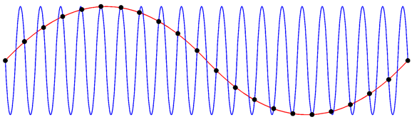
If an ADC encounters input frequencies greater than its sampling frequency divided by two, the ADC creates sub-harmonics of the high frequency, a phenomenon known as aliasing. Not good. For instance, a sampling rate of 40,000 samples/second requires the analog input signal only be composed of frequencies below 20kHz. In the following illustration, we the blue input signal and the red plot traced by the ADC, whose sampling rate was too slow to capture the true frequency.
This is why I like the idea of using the 2122Hz low-pass filter in the phono stage, as the low pass filter not only undoes the LP's boosted highs, but it keeps going on, so tube hiss and the higher harmonics of the ticks and pops get attenuated. But let's assume that most modern ADCs are run so fast that no phono cartridge can put out high enough a frequency to trip up the ADC, even when they encounter a nasty tick or pop. This then leaves the problem of voltage over-loading. A 40dB phono stage works on the assumption that a cartridge will put out 5mV of signal which the preamp will amplify up to 0.5V of peak output. If we run a flat phono preamp, with no low-pass filtering of high frequencies, we should back off its gain by 20dB, so only 20dB would be needed, as the LP contains a +20dB boost of frequencies above 20kHz. Most single-ended ADCs present an input overload voltage of 1Vpk; most differential ADCS, 2Vpk-to-pk. So we should add +6dB to the gain requirement, bringing us to +26dB, or a voltage gain of 20. This is not much gain at all for a tube circuit. An Aikido stage with a 12AY7/6072 input tube yields a gain of 20 (+26dB).
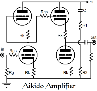
Since most ADCs have a volume potentiometer at their inputs, we could use a 12AX7 as the input tube and get a gain of 50 (+34dB), for those extra quiet classical LPs. Of course, a low-output moving-coil cartridge will need lots more gain. One possibility is the Aikido cascade.
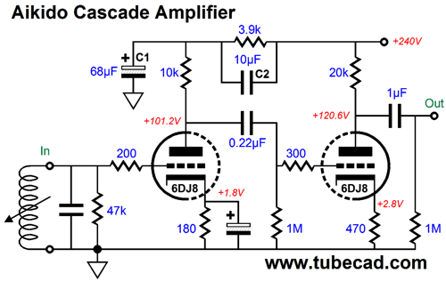
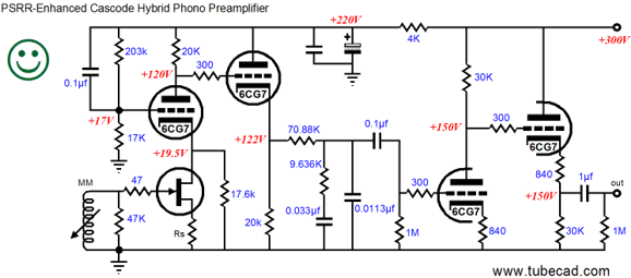
Capacitors C1 & C2 set the ratio of power-supply noise leak through the input triode's plate, which the second stage then amplifies and inverts, creating a power-supply noise null at the output. In SPICE simulations, the above circuit realized a gain of 376 (51.5dB), with a PSRR of -37dB. Without the Aikido mojo, the PSRR would be about -6dB for this circuit. This is such an easy way out, why not take it? Maybe we should, but I have my reservations. I have actually looked into the source-code for digital filtering and DSP and it is fairly easy to implement, but it is not the same a real filter. (I remember encountering phrase such as, "fast and dirty," which make me nervous.) More research is needed, by me at least.
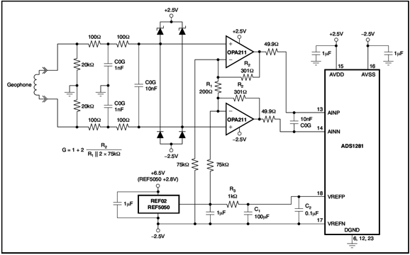
Differential Phono Preamps for Ripping
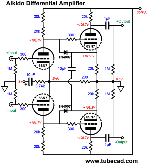
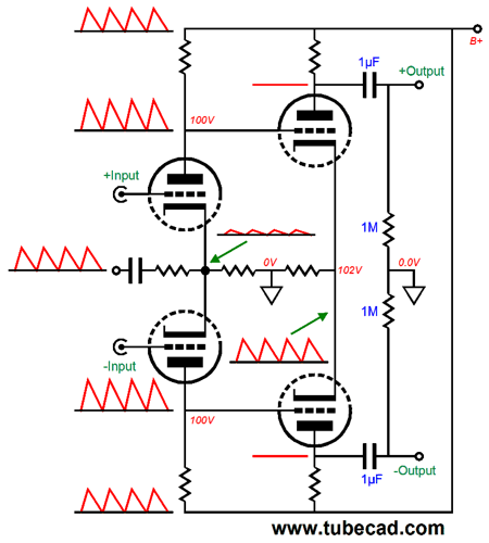
There is so much going here that I do not know where to start. Let's start with the Aikido mojo. We purposely inject a sampling of the power-supply noise into the differential input stage's cathodes. This noise then gets added in phase to the power-supply noise at the plates. The second differential stage then superimposes the power-supply noise upon the shared cathode resistor, which causes its plates to see a power-supply-noise null, as an inverted version of the power-supply noise will combine with the power-supply noise and cancel.
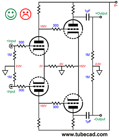
The second strange feature is the two cathode resistors and the 10µF capacitor on the second differential amplifier stage. Why are they there? They are there because the following cascading differential amplifier presents some problems.
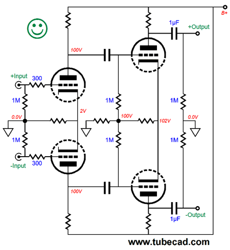
If nothing looks out of sorts here, then you probably spend too much doing SPICE simulations. In SPICE, this circuit works flawlessly. Reality isn't so lucky. In real life, all triodes are not perfectly matched, nor are all 20k resistors. In SPICE they are. What are the odds that the two plates in the input tube will rest at exactly the same voltage. And even if they did today, what will happen a month from now? One so0lution is to use two internal coupling capacitors.
This certainly presents equal grid voltage to the second differential amplifier stage, but it does little to solve the problem of poorly matched triodes.
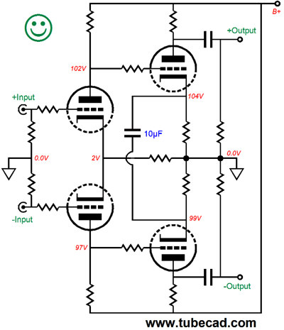
Using two cathode resistors and the single large-valued capacitor allows each output triode to find its own idle voltages and current flow. So is the best solution to creating a differential/balanced phono preamp for ripping LPs? It might be, if I could figure out a way to implement the 75µS low-pass filter. I cannot, at least not yet. The more I think about it, I think that a differential cascode, not cascade is the better path to follow.
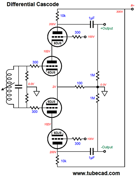
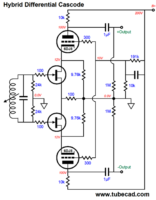
This is the basic circuit topology. It offers very high gain, roughly equal to the transconductance of the bottom triodes against the plate resistors at the top. The one big problem with all cascodes is that they offer almost no power-supply-rejection ratio (PSRR). This may not prove to be a problem, as the driver stage in front of the ADC will offer a good amount of CMRR, which will ignore the noise common to both phases of output. This circuit, however, runs flat, offering no Inverse RIAA equalization. The following variation includes some Aikido mojo.
If this topology looks vaguely familiar, no doubt is due to having seen a non-differential version on post 119.
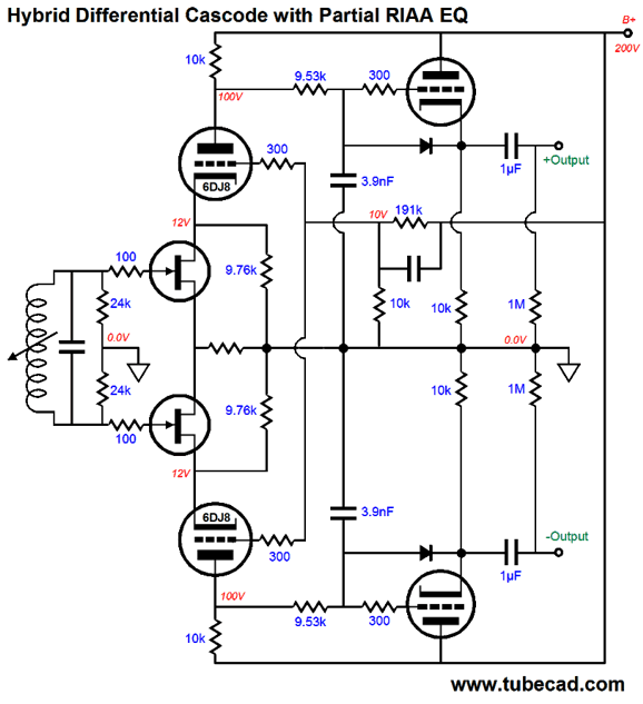
The FET offer lower noise and far lower microphonics than any tube. Its drain present a near infinite impedance, so effectively, the 17.6k cathode resistor in parallel with the FET still presents 17.6k of resistance to the cathode. All of the power-supply noise is fed to the leftmost triode's grid, so most of this noise get superimposed upon the 17.6k resistor, which causes the 20k plate resistor to undergo current variation that end up nulling the B+ noise at the plate. (I can't believe that I haven't heard from the MacArthur Fellows Program yet. Last year, two sculptors won awards. Surely, post-modern, electronic-topological art deserves equal recognition. ;) The following variation not only imposes the 2122Hz low-pass filtering, it also includes the same Aikido mojo.
The FETs each draw 9mA, while the triodes above them draw 10mA, with a little over a milliamp travels through the 9.76k resistors. The two diodes are there to protect the cathode follower triodes at startup, when the input triodes are cold and not conducting; thus, the cathode follower triodes won't see 0V on their cathodes while their grids see +300V—not good. I am going to have to end here, although I much more to say on this topic. Next time. Until then, here is quiz: what is the following? It looks like a tube, but is it?
Those with dirty minds expect to be wrong. Click on the image to find out what it is.
Special Thanks If you have been reading my posts, you know that my lifetime goal is reaching post number one thousand. I have 627 more to go. I should easily be able to hit post 400 this year. My second goal is to gather 1,000 patrons. I have 969 patrons to go. If you enjoyed reading this post from me, then you might consider becoming one of my patrons at Patreon.com.
//JRB
User Guides for GlassWare Software Since I am still getting e-mail asking how to buy these GlassWare software programs:
For those of you who still have old computers running Windows XP (32-bit) or any other Windows 32-bit OS, I have setup the download availability of my old old standards: Tube CAD, SE Amp CAD, and Audio Gadgets. The downloads are at the GlassWare-Yahoo store and the price is only $9.95 for each program. http://glass-ware.stores.yahoo.net/adsoffromgla.html So many have asked that I had to do it. WARNING: THESE THREE PROGRAMS WILL NOT RUN UNDER VISTA 64-Bit or WINDOWS 7 & 8 or any other 64-bit OS. One day, I do plan on remaking all of these programs into 64-bit versions, but it will be a huge ordeal, as programming requires vast chunks of noise-free time, something very rare with children running about. Ideally, I would love to come out with versions that run on iPads and Android-OS tablets.
//JRB |
Kit User Guide PDFs
And
High-quality, double-sided, extra thick, 2-oz traces, plated-through holes, dual sets of resistor pads and pads for two coupling capacitors. Stereo and mono, octal and 9-pin printed circuit boards available.
Designed by John Broskie & Made in USA Aikido PCBs for as little as $24 http://glass-ware.stores.yahoo.net/
The Tube CAD Journal's first companion program, TCJ Filter Design lets you design a filter or crossover (passive, OpAmp or tube) without having to check out thick textbooks from the library and without having to breakout the scientific calculator. This program's goal is to provide a quick and easy display not only of the frequency response, but also of the resistor and capacitor values for a passive and active filters and crossovers. TCJ Filter Design is easy to use, but not lightweight, holding over 60 different filter topologies and up to four filter alignments: While the program's main concern is active filters, solid-state and tube, it also does passive filters. In fact, it can be used to calculate passive crossovers for use with speakers by entering 8 ohms as the terminating resistance. Click on the image below to see the full screen capture.
Tube crossovers are a major part of this program; both buffered and un-buffered tube based filters along with mono-polar and bipolar power supply topologies are covered. Available on a CD-ROM and a downloadable version (4 Megabytes). |
||


| www.tubecad.com Copyright © 1999-2017 GlassWare All Rights Reserved |